Since the size of transport block is not fixed, often a question comes to mind as to how transport block size is calculated in LTE.
BackGround
If we only consider "Uplink direction" and we assume that the UE is already attached to the network, then data is first received by PDCP (Packet data compression protocol) layer. This layer performs compression and ciphering / integrity if applicable. This layer will pass on the data to the next layer i.e. RLC Layer which will concatenate it to one RLC PDU.
RLC layer will concatenate or segment the data coming from PDCP layer into correct block size and forward it to the MAC layer with its own header. Now MAC layer selects the modulation and coding scheme configures the physical layer. The data is now in the shape of transport block size and needed to be transmitted in 1ms subframe.
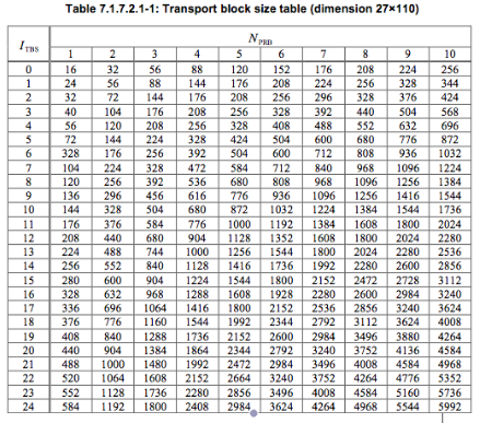
Now from the Table 7.1.7.2.1-1 the value of Transport block size is 776 bits for ITBS = 18 and NPRB=2
Please check this Throughput Calculator which takes MCS values and number of resource blocks as input to calculate the downlink throughput
code rate = (TBS + CRC) / (RE x Bits per RE)
where
TBS = Transport block size as we calculated from Table 7.1.7.2.1-1
CRC = Cyclic redundancy check i.e. Number of bits appended for error detection
RE = Resource elements assigned to PDSCH or PUSCH
Bits per RE = Modulation scheme used
While we know the values of TBS, CRC and bits per RE (modulation order), it is not easy to calculate the exact amount of RE used for PDSCH or PUSCH since some of the REs are also used by control channels like PDCCH, PHICH etc
In our case, lets assume that 10% of RE‘s are assigned for control channels then
TBS = 776
CRC = 24
RE = 2 (RB) x 12 (subcarriers) x 7 (assuming 7 ofdm symbols) x 2 (slots per subframe) x 0.9 (10% assumption as above) = 302 REs
Bits per RE = 6 (Modulation order from table 7.1.7.1-1)
So
code rate = (776 + 24) / (302 * 6 ) = 0.4
BackGround
If we only consider "Uplink direction" and we assume that the UE is already attached to the network, then data is first received by PDCP (Packet data compression protocol) layer. This layer performs compression and ciphering / integrity if applicable. This layer will pass on the data to the next layer i.e. RLC Layer which will concatenate it to one RLC PDU.
RLC layer will concatenate or segment the data coming from PDCP layer into correct block size and forward it to the MAC layer with its own header. Now MAC layer selects the modulation and coding scheme configures the physical layer. The data is now in the shape of transport block size and needed to be transmitted in 1ms subframe.
Transport Block size
Now how much bits are transferred in this 1ms transport block size?
It depends on the MCS (modulation and coding scheme) and the number of resource blocks assigned to the UE. We have to refer to the Table 7.1.7.1-1 and Table 7.1.7.2.1-1 from 3GPP 36.213
Lets assume that eNB assigns MCS index 20 and 2 resource blocks (RBs) on the basis of CQI and other information for downlink transmission on PDSCH. Now the value of TBS index is 18 as seen in Table 7.1.7.1-1
After knowing the value of TBS index we need to refer to the Table 7.1.7.2.1-1 to find the accurate size of transport block (Only portion of the table is shown here while for the complete range of values refer to 3gpp document 36.213 http://www.quintillion.co.jp/3GPP/Specs/36213-920.pdf)
Throughput
Throughput is simply = Transport block size*(1000) = 776 *1000 = 776000 bits / seconds = 0.77 mbps (Assuming MIMO not used)Please check this Throughput Calculator which takes MCS values and number of resource blocks as input to calculate the downlink throughput
Code Rate
In simple words, code rate can be defined as how effectively data can be transmitted in 1ms transport block or in other words, it is the ratio of actual amount of bits transmitted to the maximum amount of bits that could be transmitted in one transport blockcode rate = (TBS + CRC) / (RE x Bits per RE)
where
TBS = Transport block size as we calculated from Table 7.1.7.2.1-1
CRC = Cyclic redundancy check i.e. Number of bits appended for error detection
RE = Resource elements assigned to PDSCH or PUSCH
Bits per RE = Modulation scheme used
While we know the values of TBS, CRC and bits per RE (modulation order), it is not easy to calculate the exact amount of RE used for PDSCH or PUSCH since some of the REs are also used by control channels like PDCCH, PHICH etc
In our case, lets assume that 10% of RE‘s are assigned for control channels then
TBS = 776
CRC = 24
RE = 2 (RB) x 12 (subcarriers) x 7 (assuming 7 ofdm symbols) x 2 (slots per subframe) x 0.9 (10% assumption as above) = 302 REs
Bits per RE = 6 (Modulation order from table 7.1.7.1-1)
So
code rate = (776 + 24) / (302 * 6 ) = 0.4


