opencv实现摄像头内外参数标定
Posted
tags:
篇首语:本文由小常识网(cha138.com)小编为大家整理,主要介绍了opencv实现摄像头内外参数标定相关的知识,希望对你有一定的参考价值。
我用opencv自带的摄像头标定程序跑了下,可以用。现在想加段程序,用cvCalibrateCamera2来通过摄像头拍的图片算出摄像头的内外参数,不知道该如何加,结果也不知道如何显示。望高手指点下。
PS:我刚学vs2005和opencv没多久,对摄像头标定的理论知识了解了段时间。
我从网上弄个程序跑了下,可以算内参等参数了。这个问题基本解决了,有需要了解的可以站短我。但怎么把一张有后仰角度的图像转换成俯视角度的图像呢?就是校正因摄像头而引起的变形,用cvUndistort2?如何编译?
del /f /q list_of_images_auto(bmp).txt
dir *.bmp /B >> list_of_images_auto(bmp).txt
OpenCV_Example_Calibration.exe -w 7 -h 8 -s 5 -o camera.txt -op -oe list_of_images_auto(bmp).txt
pause
其中-o camera.txt表示输出参数的文件名。
不过这样用着不爽。
你看源代码里面
cvWrite( fs, "camera_matrix", camera_matrix );
cvWrite( fs, "distortion_coefficients", dist_coeffs );
的地方,知道什么意思了吧,向txt里面写这两个参数
我后来是这么存的
cvSave("DistortionMatrix.xml",dist_coeffs);
cvSave("IntrinsicsMatrix.xml",camera_matrix);
这样下次调用的时候可以直接用矩阵拿来计算矫正
intrinsic = (CvMat*)cvLoad("IntrinsicsMatrix.xml");
distortion = (CvMat*)cvLoad("DistortionMatrix.xml");
。。。
cvInitUndistortMap(this->imgprocess.intrinsic, this->imgprocess.distortion, this->imgprocess.mapx, this->imgprocess.mapy);
等本回答被提问者采纳 参考技术B 能不能教教我怎么标定 我不会用opencv····软件装好了
双目立体视觉摄像头的标定矫正世界坐标计算(opencv)
使用opencv对双目立体视觉摄像头进行标定和矫正
摄像头标定准备工作
使用双目摄像头拍摄贴有棋盘格的平面,拍摄多组图片,要保证左右相机均能够拍摄到完整的方格。并测量棋盘格方格的实际尺寸。
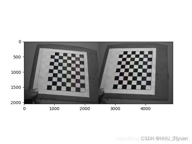
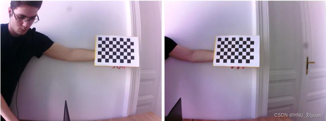
摄像头标定
对步骤1拍摄的到的左右相机的照片进行处理,分别计算左右相机的参数。
cheese_size = (11, 8) # 棋盘格图片在长宽方向上包含格子的个数
corner_num = cheese_size[0] * cheese_size[1]
unit = 20  # 实际的格子间距这里是 20mm

objp = np.zeros((corner_num, 3), np.float32)
objp[:, :2] = np.mgrid[0:cheese_size[0], 0:cheese_size[1]].T.reshape(-1, 2)
objp *= unit
print("objp:", objp.shape)
stereo_right_images = []
stereo_left_images = []
objpoints = []
save = True

for fn in fns:
    print(fn)
    left_img = cv2.imread(fn)
    stereo_left_images.append(left_img) # opencv读取视频

    right_img = cv2.imread(fn.replace('left', 'right'))
    stereo_right_images.append(right_img)

    objpoints.append(objp)
print(len(stereo_left_images), len(stereo_right_images))

# 单目标定
x, stereo_right_corners = calibrate(
    stereo_right_images, objpoints, cheese_size=cheese_size, show_img=True, fnames=fns)
stereo_right_ret, stereo_right_mtx, stereo_right_dist, stereo_right_rvecs, stereo_right_tvecs = x
# stereo_nir_dist = np.zeros_like(stereo_nir_dist)
print('right cali done...')

x, stereo_left_corners = calibrate(
    stereo_left_images, objpoints, cheese_size=cheese_size, show_img=True, fnames=fns)
stereo_left_ret, stereo_left_mtx, stereo_left_dist, stereo_left_rvecs, stereo_left_tvecs = x
print('left cali done...')

if _DIST_:
    print('--------------------------------------------------------------------')
    stereo_right_dist = np.zeros_like(stereo_right_dist)
    stereo_left_dist = np.zeros_like(stereo_left_dist)

# 双目标定
retval, stereo_left_mtx, stereo_left_dist, stereo_right_mtx, stereo_right_dist, R_left2right, T_left2right, E_left2right, F_left2right= \\
    cv2.stereoCalibrate(np.array(objpoints), np.squeeze(np.array(stereo_left_corners)),
                        np.squeeze(np.array(stereo_right_corners)
                                   ), stereo_left_mtx, stereo_left_dist,
                        stereo_right_mtx, stereo_right_dist, (stereo_left_images[0].shape[0],
                                                          stereo_left_images[0].shape[1])
                        # flags=cv2.CALIB_RATIONAL_MODEL
                        )  # python3 transfer stereo_left -> stereo_righ tflags=cv2.CALIB_RATIONAL_MODEL
h, w, c = stereo_right_images[0].shape
print('stereo cali done...')

if _DIST_:
    stereo_right_dist = np.zeros_like(stereo_right_dist)
    stereo_left_dist = np.zeros_like(stereo_left_dist)
其中的calibrate函数为:
def calibrate(images, objpoints, cheese_size, show_img=False, fnames=[]):
    # termination criteria
    criteria = (cv2.TERM_CRITERIA_EPS + cv2.TERM_CRITERIA_MAX_ITER, 50, 0.001) # 终止迭代标准,最大迭代次数或者到达精度
    imgpoints = []
    num = 0
    for img in images:
        gray = cv2.cvtColor(img, cv2.COLOR_BGR2GRAY)
        ret, corners = cv2.findChessboardCorners(gray, cheese_size, None)# 检测输入图片是否含有棋盘图片

        # If found, add object points, image points (after refining them)
        if ret == True:
            cv2.cornerSubPix(gray, corners, (5, 5), (-1, -1), criteria) # 亚像素角点检测
            # print(corners)
            imgpoints.append(corners)
            if show_img:
                # Draw and display the corners
                img = np.copy(img)
                cv2.drawChessboardCorners(img, cheese_size, corners, ret) # 棋盘格角点绘制
                cv2.imshow('img'  , img)
                cv2.imwrite("right.jpg", img)
                cv2.waitKey(3)
        num = num + 1
    if show_img:
        cv2.destroyAllWindows()


    # input('回车下一步')
    return cv2.calibrateCamera(objpoints, imgpoints, gray.shape[::-1], None, None), imgpoints #求出内参和每一个视角的外参数
此过程能够自动检测图片中的棋盘格图片进行参数计算,得到两个摄像头的内外参数矩阵,以及两个摄像头之间的位置关系。
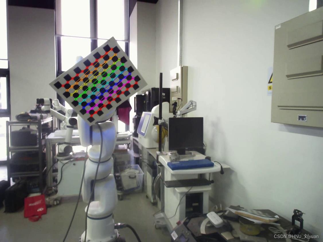
摄像头矫正
此时能够得到每一个摄像头的参数,但是实际中并不是理想的双目视觉模型,Bouguet立体校正算法,其核心原理是通过像素平面透视变换,使左右图像重投影误差最小,使双目系统最接近理想状态。也就是立体矫正。
# 双目矫正
R1, R2, P1, P2, Q, validPixROI1, validPixROI2 = cv2.stereoRectify(
    stereo_left_mtx, stereo_left_dist, stereo_right_mtx, stereo_right_dist, (w, h), R_left2right, T_left2right, alpha=0)
R1[0, :] *= -1
R2[0, :] *= -1
print('stereo rectify done...')

# 得到映射变换
stereo_left_mapx, stereo_left_mapy = cv2.initUndistortRectifyMap(
    stereo_left_mtx, stereo_left_dist, R1, P1, (w, h), 5)
stereo_right_mapx, stereo_right_mapy = cv2.initUndistortRectifyMap(
    stereo_right_mtx, stereo_right_dist, R2, P2, (w, h), 5)
print('initUndistortRectifyMap done...')
并可以将其中的关键参数保存下来。
if save:
    np.save('P1', P1)
    np.save('P2', P2)
    np.save('stereo_right_mtx', stereo_right_mtx)
    np.save('stereo_right_dist', stereo_right_dist)
    np.save('stereo_left_mtx', stereo_left_mtx)
    np.save('stereo_left_dist', stereo_left_dist)
    np.save('R_left2right', R_left2right)
    np.save('T_left2right', T_left2right)
通过可视化验证是否对其:
# 可视化验证,看网格是否对齐
def drawLine(img, num=16):
    h, w, *_ = img.shape
    for i in range(0, h, h // num):
        cv2.line(img, (0, i), (w, i), (0, 255, 0), 1, 8)
    return img

for fn in fns:
    left_img = cv2.imread(fn)
    right_img = cv2.imread(fn.replace('left', 'right'))

    frame0 = cv2.remap(right_img, stereo_right_mapx,
                       stereo_right_mapy, cv2.INTER_LINEAR)
    frame1 = cv2.remap(left_img, stereo_left_mapx,
                       stereo_left_mapy, cv2.INTER_LINEAR)

    img = np.concatenate((frame0, frame1), axis=1).copy()
    img = drawLine(img, 32)
    cv2.imshow('img', img)
    ret = cv2.waitKey(3)
矫正之后的图片棋盘格之间应该是对齐的,在同一高度。
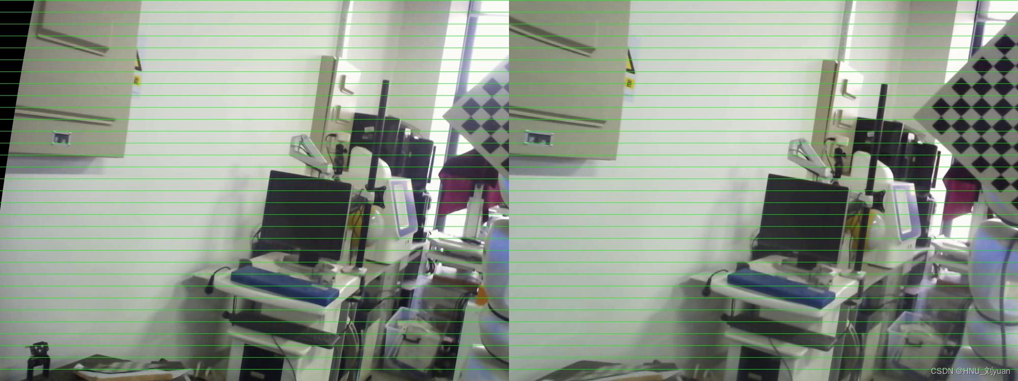
此时就完成了相机的标定和矫正工作。
世界坐标计算
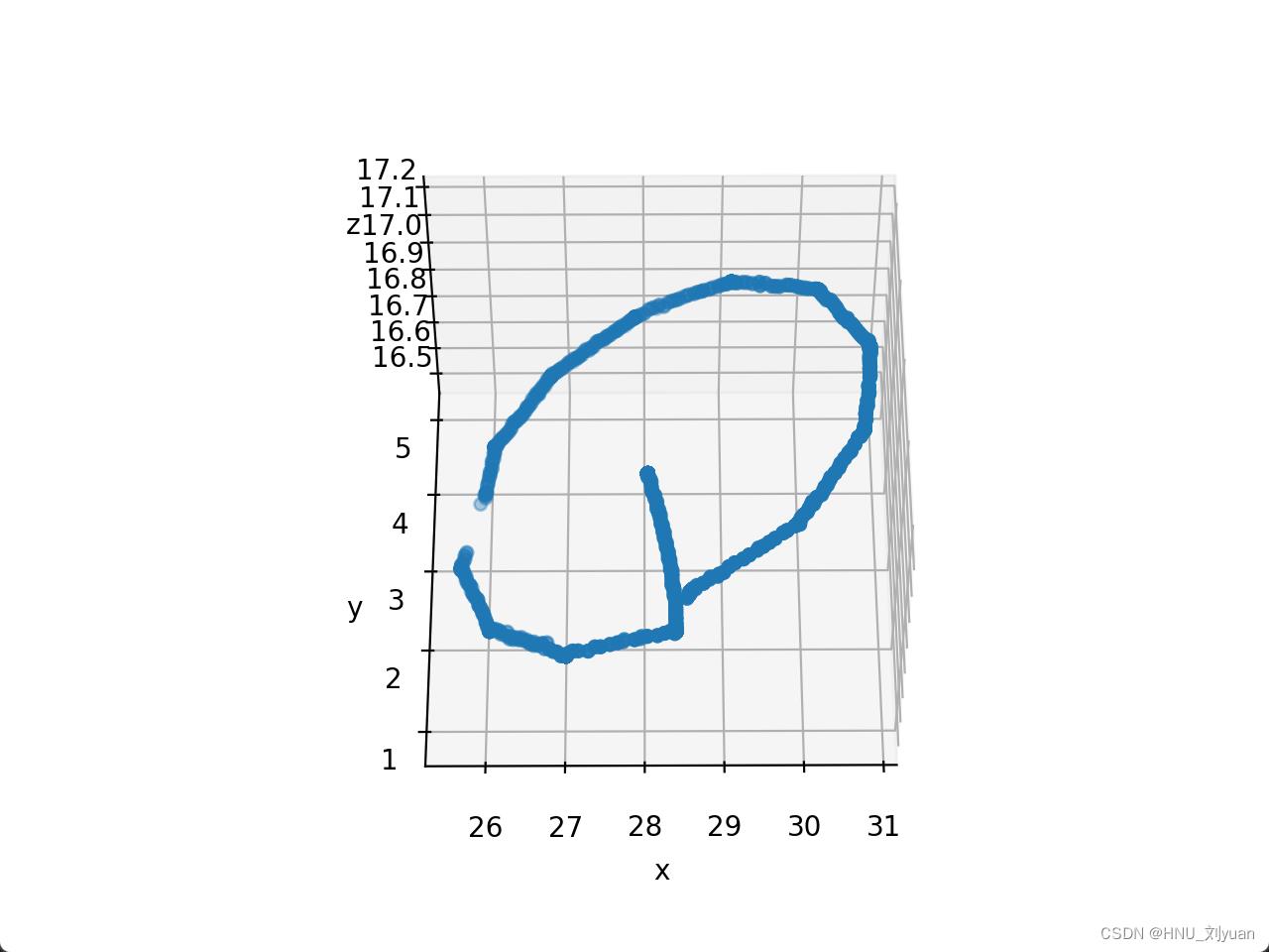
得到相机的参数之后,假如知道同一个点在左右视频中的位置,就能够计算其三维坐标位置。
利用跟踪或者其他算法得到某个固定点在左右摄像头的像素坐标,保存为txt文件,使用left_path 和right_path 代表其路径。
import numpy as np
import matplotlib.pylab as plt
import math
# [K1,K2,P1,P2,k3]
def read_point(left_path,right_path):
    point_r=[]
    point_l=[]
    with open(left_path,"r") as f:
        line = f.readline().strip('\\n')
        while line:
            temp=line.split(' ')
            point=[int(temp[0]), int(temp[1])]
            point_l.append(point)
            line=f.readline().strip('\\n')
    with open(right_path, "r") as f:
        line = f.readline().strip('\\n')
        while line:
            temp = line.split(' ')
            point = [int(temp[0]), int(temp[1])]  #1280
            point_r.append(point)
            line = f.readline().strip('\\n')
    point_r = np.array(point_r)
    point_l = np.array(point_l)
    return point_l,point_r

def computexyz(point_l, point_r, M_l,M_r):
    # compute XYZ
    ul = point_l[0]
    vl = point_l[1]
    ur = point_r[0]
    vr = point_r[1]
    # A = np.zeros((4,3))
    A = np.array([[ul * M_l[2][0] - M_l[0][0], ul * M_l[2][1] - M_l[0][1], ul * M_l[2][2] - M_l[0][2]],
                  [vl * M_l[2][0] - M_l[1][0], vl * M_l[2][1] - M_l[1][1], vl * M_l[2][2] - M_l[1][2]],
                  [ur * M_r[2][0] - M_r[0][0], ur * M_r[2][1] - M_r[0][1], ur * M_r[2][2] - M_r[0][2]],
                  [vr * M_r[2][0] - M_r[1][0], vr * M_r[2][1] - M_r[1][1], vr * M_r[2][2] - M_r[1][2]]])
    b = np.array([M_l[0][3] - ul * M_l[2][3], M_l[1][3] - vl * M_l[2][3], M_r[0][3] - ur * M_r[2][3],
                  M_r[1][3] - vr * M_r[2][3]])
    temp1 = np.linalg.inv(np.matmul(A.T, A))
    temp2 = np.matmul(A.T, b)
    point_xyz = np.matmul(temp1, temp2)
    return point_xyz


left_path = "data/point_left_c.txt"
right_path = "data/point_right_c.txt"
point_l,point_r = read_point(left_path,right_path)

distRight=np.load("stereo_right_dist.npy").squeeze()
distLeft=np.load("stereo_left_dist.npy").squeeze()
print(distLeft)
print(distRight)
m,n=point_r.shape


K_r = np.load("stereo_right_mtx.npy")
R_r = np.load("R_left2right.npy")
t_r = np.load("T_left2right.npy").squeeze()
R_l = np.eye(3)
t_l = np.array([0,0,0])
P_r = np.zeros((3,4))
P_r[:, 0:3] = R_r
P_r[:, 3] = t_r

M_r=np.matmul(K_r,P_r)
K_l = np.load("stereo_left_mtx.npy")

P_l = np.zeros((3,4))
P_l[:, 0:3] = R_l
P_l[:, 3] = t_l

M_l=np.matmul(K_l,P_l)
Point = []
for i in range(len(point_l)):
    Pointxyz = computexyz(point_l[i],point_r[i],M_l,M_r)
    Point.append(Pointxyz)

Point = np.array(Point)


fig = plt.figure()
ax = fig.add_subplot(111, projection='3d')

ax.scatter(Point[:,0], Point[:,1], Point[:,2])

ax.set_xlabel('x')
ax.set_ylabel('y')
ax.set_zlabel('z')

plt.show()
即可得到如下所示的三维轨迹图。
具体的原理部分可以参考其余博客,写的都挺好。
以上是关于opencv实现摄像头内外参数标定的主要内容,如果未能解决你的问题,请参考以下文章
如何利用opencv计算图像畸变系数,并进行校正与摄像机标定?