企业内部网络的多出口相互冗余备份与负载均衡
Posted 正月十六工作室
tags:
篇首语:本文由小常识网(cha138.com)小编为大家整理,主要介绍了企业内部网络的多出口相互冗余备份与负载均衡相关的知识,希望对你有一定的参考价值。
企业内部网络的多出口相互冗余备份与负载均衡
VRRP简介
虚拟路由冗余协议VRRP(Virtual Router Redundancy Protocol)通过把几台路由设备联合组成一台虚拟的路由设备,将虚拟路由设备的IP地址作为用户的默认网关实现与外部网络通信。当网关设备发生故障时,VRRP机制能够选举新的网关设备承担数据流量,从而保障网络的可靠通信。
项目背景
企业为了提高网络可用性,增强了网络的健壮性,希望网络的核心层能实现冗余链路的同时能消除网络中的环路。此外,针对核心层的设备,希望实现用户的通信业务不中断。
项目需求分析
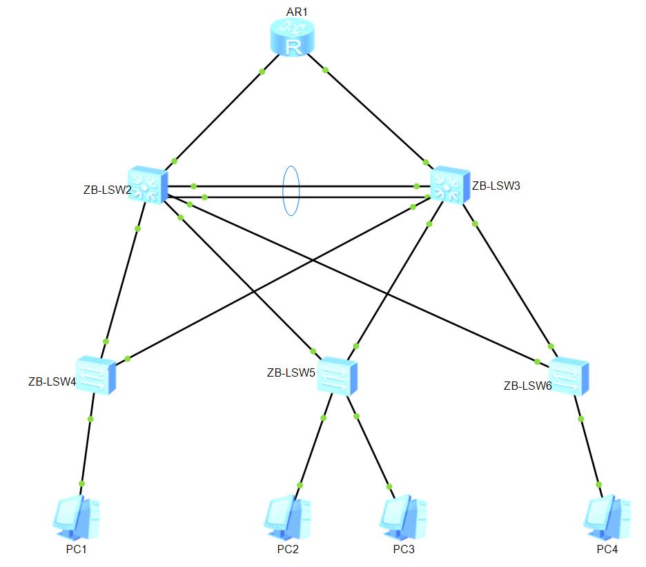
如下图所示ZB-LSW2与ZB-LSW3为企业内部网络核心层同时也是客户端的网关设备,ZB-LSW4、ZB-LSW5、ZB-LSW6是企业内网的接入层交换机,AR1连接外网,用loopback接口模拟公网。
1、部署 Eth-trunk 链路聚合,把多个独立的物理接口绑定在一起作为一个大带宽的逻辑接口使用,这样既不用替换接口板也不会浪费IP地址资源可拓展接口带宽,增加链路可靠性以及流量的负载分担,配置动态OSPF协议实现底层路由通信。
2、所有交换机部署MSTP,作为防环协议,有实现负载分担的作用,同时也实现网络核心层的冗余链路。
3、在网关设备上配置VRRP主备备份功能,实现网关的冗余备份;为减轻主用设备上数据流量的承载压力,可以通过配置VRRP负载分担实现上行流量的负载均衡。
项目规划
项目中的IP规划如下图所示。其中ZB-LSW2作为vlan10、20的主用设备,vlan30、40的备用设备。ZB-LSW3作为vlan30、40的主用设备,vlan10、20的备用设备。

项目实施
基础配置
1、配置路由器AR1
#在AR1上配置设备名称、接口的IP地址、配置环回口及配置动态OSPF协议实现底层路由通信。
1.1、配置设备名称、配置接口IP地址及环回口地址。
system-view
[Huawei] sysname AR1
[AR1]interface GigabitEthernet0/0/1
[AR1-GigabitEthernet0/0/1] ip address 192.168.12.2 255.255.255.0
[AR1-GigabitEthernet0/0/1]quit
[AR1]interface GigabitEthernet0/0/2
[AR1-GigabitEthernet0/0/2] ip address 192.168.13.2 255.255.255.0
[AR1-GigabitEthernet0/0/2]quit
[AR1]interface loopback1
[AR1-LoopBack1]ip address 10.10.10.10 32
[AR1-LoopBack1]quit
1.2、配置OSPF协议及宣告区域内路由
[AR1]ospf 10 router-id 1.1.1.1
[AR1-ospf-10]area 0
[AR1-ospf-10-area-0.0.0.0]network 192.168.12.0 0.0.0.255
[AR1-ospf-10-area-0.0.0.0]network 192.168.13.0 0.0.0.255
[AR1-ospf-10-area-0.0.0.0]network 10.10.10.10 0.0.0.0
[AR1-ospf-10-area-0.0.0.0]quit
[AR1-ospf-10]quit
2、配置三层交换机ZB-LSW2和ZB-LSW3
分别在ZB-LSW2和ZB-LSW3上配置设备名、创建VLAN、配置接口模式及SVI地址、在两台核心交换机之间采用手工模式配置链路聚合、配置动态OSPF协议实现底层路由通信。
2.1、配置ZB-LSW2三层交换机
1)配置设备名、创建VLAN、配置接口模式及SVI地址。
system-view
[Huawei]sysname ZB-LSW2
[ZB-LSW2]undo inf enable
[ZB-LSW2]vlan batch 12 10 20 30 40
[ZB-LSW2]interface gigabitethernet 0/0/24
[ZB-LSW2-GigabitEthernet0/0/24]port link-type access
[ZB-LSW2-GigabitEthernet0/0/24]port default vlan 12
[ZB-LSW2-GigabitEthernet0/0/24]quit
[ZB-LSW2]port-group 1
[ZB-LSW2-port-group-1]group-member gigabitethernet 0/0/11 to gigabitethernet 0/0
/13
[ZB-LSW2-port-group-1]port link-type trunk
[ZB-LSW2-port-group-1]port trunk allow vlan 2 to 50
[ZB-LSW2-port-group-1]quit
[ZB-LSW2]interface vlan 12
[ZB-LSW2-Vlanif12]ip address 192.168.12.1 24
[ZB-LSW2-Vlanif12]quit
[ZB-LSW2]interface Vlanif10
[ZB-LSW2-Vlanif10] ip address 192.168.10.253 24
[ZB-LSW2-Vlanif10]quit
[ZB-LSW2]interface Vlanif20
[ZB-LSW2-Vlanif20] ip address 192.168.20.253 24
[ZB-LSW2-Vlanif20]quit
[ZB-LSW2]interface Vlanif30
[ZB-LSW2-Vlanif30] ip address 192.168.30.253 24
[ZB-LSW2]interface Vlanif40
[ZB-LSW2-Vlanif40] ip address 192.168.40.253 24
[ZB-LSW2-Vlanif40]quit
2)配置端口聚合
[ZB-LSW2]interface Eth-Trunk1
[ZB-LSW2-Eth-Trunk1]trunkport GigabitEthernet 0/0/21
[ZB-LSW2-Eth-Trunk1]trunkport GigabitEthernet 0/0/22
[ZB-LSW2-Eth-Trunk1]port link-type trunk
[ZB-LSW2-Eth-Trunk1]port trunk allow vlan 2 to 50
[ZB-LSW2-Eth-Trunk1]quit
3)配置OSPF协议及宣告区域内路由
[ZB-LSW2] ospf 10 router-id 11.2.2.2
[ZB-LSW2-ospf-10]area 0
[ZB-LSW2-ospf-10-area-0.0.0.0]network 192.168.10.0 0.0.0.255
[ZB-LSW2-ospf-10-area-0.0.0.0]network 192.168.20.0 0.0.0.255
[ZB-LSW2-ospf-10-area-0.0.0.0]network 192.168.30.0 0.0.0.255
[ZB-LSW2-ospf-10-area-0.0.0.0]network 192.168.40.0 0.0.0.255
[ZB-LSW2-ospf-10-area-0.0.0.0]quit
[ZB-LSW2-ospf-10]quit
2.2、配置ZB-LSW3三层交换机
1)配置设备名、创建VLAN、配置接口模式及SVI地址。
system-view
[Huawei]sysname ZB-LSW3
[ZB-LSW3]undo inf enable
[ZB-LSW3]vlan batch 13 10 20 30 40
[ZB-LSW3]interface gigabitethernet 0/0/24
[ZB-LSW3-GigabitEthernet0/0/24]port link-type access
[ZB-LSW3-GigabitEthernet0/0/24]port default vlan 13
[ZB-LSW3-GigabitEthernet0/0/24]quit
[ZB-LSW3]port-group 1
[ZB-LSW3-port-group-1]group-member gigabitethernet 0/0/11 to gigabitethernet 0/0
/13
[ZB-LSW3-port-group-1]port link-type trunk
[ZB-LSW3-port-group-1]port trunk allow vlan 2 to 50
[ZB-LSW3-port-group-1]quit
[ZB-LSW3]interface vlan 13
[ZB-LSW3-Vlanif13]ip address 192.168.13.1 24
[ZB-LSW3-Vlanif13]quit
[ZB-LSW3]interface Vlanif10
[ZB-LSW3-Vlanif10] ip address 192.168.10.252 24
[ZB-LSW3-Vlanif10]quit
[ZB-LSW3]interface Vlanif20
[ZB-LSW3-Vlanif20] ip address 192.168.20.252 24
[ZB-LSW3-Vlanif20]quit
[ZB-LSW3]interface Vlanif30
[ZB-LSW3-Vlanif30] ip address 192.168.30.252 24
[ZB-LSW3-Vlanif30]quit
[ZB-LSW3]interface Vlanif40
[ZB-LSW3-Vlanif40] ip address 192.168.40.252 24
[ZB-LSW3-Vlanif40]quit
2)配置端口聚合
[ZB-LSW3]interface Eth-Trunk1
[ZB-LSW3-Eth-Trunk1]trunkport GigabitEthernet 0/0/21
[ZB-LSW3-Eth-Trunk1]trunkport GigabitEthernet 0/0/22
[ZB-LSW3-Eth-Trunk1]port link-type trunk
[ZB-LSW3-Eth-Trunk1]port trunk allow vlan 2 to 50
[ZB-LSW3-Eth-Trunk1]quit
3)配置OSPF协议及宣告区域内路由
[ZB-LSW3]ospf 10 router-id 11.3.3.3
[ZB-LSW3-ospf-10]area 0
[ZB-LSW3-ospf-10-area-0.0.0.0]network 192.168.13.0 0.0.0.255
[ZB-LSW3-ospf-10-area-0.0.0.0]network 192.168.10.0 0.0.0.255
[ZB-LSW3-ospf-10-area-0.0.0.0]network 192.168.20.0 0.0.0.255
[ZB-LSW3-ospf-10-area-0.0.0.0]network 192.168.30.0 0.0.0.255
[ZB-LSW3-ospf-10-area-0.0.0.0]network 192.168.40.0 0.0.0.255
[ZB-LSW3-ospf-10-area-0.0.0.0]quit
[ZB-LSW3-ospf-10]quit
3、配置接入层交换机ZB-LSW4、ZB-LSW5、ZB-LSW6
分别在ZB-LSW4、ZB-LSW5、ZB-LSW6上配置设备名、创建VLAN、配置接口模式。
3.1、配置ZB-LSW4接入层交换机
system-view
[Huawei]sys ZB-LSW4
[ZB-LSW4]undo in enable
[ZB-LSW4]vlan batch 10 20 30 40
[ZB-LSW4]port-group group-member gigabitEthernet0/0/1 gigabitEthernet0/0/2
[ZB-LSW4-port-group] port link-type trunk
[ZB-LSW4-GigabitEthernet0/0/1] port link-type trunk
[ZB-LSW4-port-group] port trunk allow-pass vlan 2 to 50
[ZB-LSW4-GigabitEthernet0/0/1] port trunk allow-pass vlan 2 to 50
[ZB-LSW4-port-group]quit
[ZB-LSW4]port-group group-member Ethernet0/0/1 to Ethernet0/0/10
[ZB-LSW4-port-group] port link-type access
[ZB-LSW4-port-group] port default vlan 10
[ZB-LSW4-port-group]quit
[ZB-LSW4]
3.2、配置ZB-LSW5接入层交换机
system-view
[Huawei]sys ZB-LSW5
[ZB-LSW5]undo in enable
[ZB-LSW5]vlan batch 10 20 30 40
[ZB-LSW5]port-group group-member gigabitEthernet0/0/1 gigabitEthernet0/0/2
[ZB-LSW5-port-group] port link-type trunk
[ZB-LSW5-port-group] port trunk allow-pass vlan 2 to 50
[ZB-LSW5-port-group]quit
[ZB-LSW5]port-group group-member Ethernet0/0/1 to Ethernet0/0/5
[ZB-LSW5-port-group] port link-type access
[ZB-LSW5-port-group] port default vlan 20
[ZB-LSW5-port-group]quit
[ZB-LSW5]port-group group-member Ethernet0/0/6 to Ethernet0/0/10
[ZB-LSW5-port-group] port link-type access
[ZB-LSW5-port-group] port default vlan 30
[ZB-LSW5-port-group]quit
[ZB-LSW5]
3.3、配置ZB-LSW6接入层交换机
system-view
[Huawei]sys ZB-LSW6
[ZB-LSW6]undo in enable
[ZB-LSW6]vlan batch 10 20 30 40
[ZB-LSW6]port-group group-member gigabitEthernet0/0/1 gigabitEthernet0/0/2
[ZB-LSW6-port-group] port link-type trunk
[ZB-LSW6-port-group] port trunk allow-pass vlan 2 to 50
[ZB-LSW6-port-group]quit
[ZB-LSW6]port-group group-member Ethernet0/0/1 to Ethernet0/0/10
[ZB-LSW6-port-group] port link-type access
[ZB-LSW6-port-group] port default vlan 40
[ZB-LSW6-port-group]quit
核心配置
1、在处于环形网络中的交换设备上配置MSTP基本功能
配置MST域创建多实例,域名为ZB、VLAN 10跟VLAN 30映射到实例1,VLAN 20跟VLAN 40映射到实例2,将与终端直连的交换机端口都配置为边缘端口,激活区域配置;设置ZB-LSW2为实例1的主根,为实例2为从根,设置ZB-LSW3为实例2的主根,为实例1为从根。
1.1、配置ZB-LSW2的MST域,为实例1的根桥,实例2的备份根桥。
[ZB-LSW2]stp region-configuration
[ZB-LSW2-mst-region]region-name ZB
[ZB-LSW2-mst-region] instance 1 vlan 10 30
[ZB-LSW2-mst-region] instance 2 vlan 20 40
[ZB-LSW2-mst-region]active region-configuration
[ZB-LSW2-mst-region]quit
[ZB-LSW2]stp instance 1 root primary
[ZB-LSW2]stp instance 2 root secondary
1.2、配置ZB-LSW3的MST域,为实例2的根桥,实例1的备份根桥。
[ZB-LSW3]stp region-configuration
[ZB-LSW3-mst-region]region-name ZB
[ZB-LSW3-mst-region] instance 1 vlan 10 30
[ZB-LSW3-mst-region] instance 2 vlan 20 40
[ZB-LSW3-mst-region]active region-configuration
[ZB-LSW3-mst-region]quit
[ZB-LSW3]stp instance 1 root secondary
[ZB-LSW3]stp instance 2 root primary
1.3、配置ZB-LSW4的MST域
[ZB-LSW4]stp region-configuration
[ZB-LSW4-mst-region]region-name ZB
[ZB-LSW4-mst-region] instance 1 vlan 10 30
[ZB-LSW4-mst-region] instance 2 vlan 20 40
[ZB-LSW4-mst-region]active region-configuration
[ZB-LSW4-mst-region]quit
[ZB-LSW4]port-group group-member Ethernet0/0/1 to Ethernet0/0/10
[ZB-LSW4-port-group]stp edged-port enable
[ZB-LSW4-port-group]quit
[ZB-LSW4]stp bpdu-protection
1.4、配置ZB-LSW5的MST域
[ZB-LSW5]stp region-configuration
[ZB-LSW5-mst-region]region-name ZB
[ZB-LSW5-mst-region] instance 1 vlan 10 30
[ZB-LSW5-mst-region] instance 2 vlan 20 40
[ZB-LSW5-mst-region]active region-configuration
[ZB-LSW5-mst-region]quit
[ZB-LSW5]stp bpdu-protection
[ZB-LSW5]port-group group-member Ethernet0/0/1 to Ethernet0/0/10
[ZB-LSW5-port-group]stp edged-port enable
[ZB-LSW5-port-group]quit
1.5、配置ZB-LSW6的MST域
[ZB-LSW6]stp region-configuration
[ZB-LSW6-mst-region]region-name ZB
[ZB-LSW6-mst-region] instance 1 vlan 10 30
[ZB-LSW6-mst-region] instance 2 vlan 20 40
[ZB-LSW6-mst-region]active region-configuration
[ZB-LSW6-mst-region]quit
[ZB-LSW6]stp bpdu-protection
[ZB-LSW6]port-group group-member Ethernet0/0/1 to Ethernet0/0/10
[ZB-LSW6-port-group]stp edged-port enable
[ZB-LSW6-port-group]quit
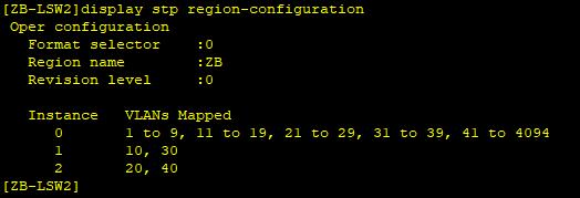
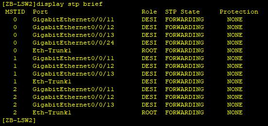
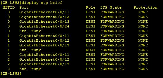
2、在配置MST域交换机上执行命令查看设备生成树相关信息
#在配置MST域的交换机上执行display stp region-configuration命令查看一下设备当前生效的MST域配置信息;在配置MST域的交换机上执行display stp brief命令,查看生成树的端口状态。
2.1、在ZB-LSW2执行display stp region-configuration命令,查看当前生效的MST域配置信息,其它交换机一样,不一一列举。
2.2、ZB-LSW2上执行display stp brief命令,查看生成树端口转发状态
#在MSTI1中,由于ZB-LSW2是根桥,ZB-LSW2的端口GE0/0/11、GE0/0/12、GE0/0/13、Eth-Trunk1被选举为指定端口。在MSTI2中,由于ZB-LSW2是备份根桥,ZB-LSW2的端口GE0/0/11、GE0/0/12、GE0/0/13被选举为指定端口,Eth-Trunk 1被选举为根端口。
2.3、ZB-LSW3上执行display stp brief命令,查看生成树端口转发状态
#在MSTI1中,由于ZB-LSW3是备份根桥,ZB-LSW3的端口GE0/0/11、GE0/0/12、GE0/0/13被选举为指定端口,Eth-Trunk 1被选举为根端口;在MSTI2中,由于ZB-LSW3是根桥,ZB-LSW3的端口GE0/0/11、GE0/0/12、GE0/0/13、Eth-Trunk1被选举为指定端口。
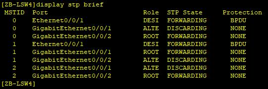
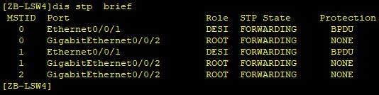
2.4、ZB-LSW4上执行display stp brief命令,查看生成树端口转发状态
#ZB-LSW4的端口GE0/0/1在MSTI1中为根端口,在MSTI2中被阻塞;ZB-LSW4的端口GE0/0/2,在MSTI1中被阻塞,在MSTI2中为根端口。
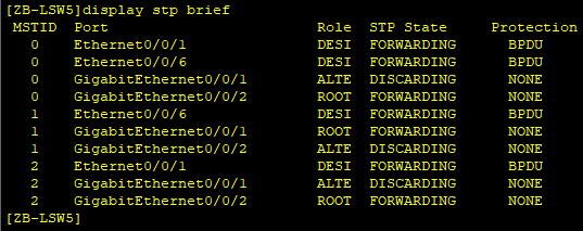
2.5、ZB-LSW5上执行display stp brief命令,查看生成树端口转发状态
#ZB-LSW5的端口GE0/0/1在MSTI1中为根端口,在MSTI2中被阻塞;ZB-LSW5的端口GE0/0/2,在MSTI1中被阻塞,在MSTI2中为根端口。
2.6、ZB-LSW6上执行display stp brief命令,查看生成树端口转发状态
#ZB-LSW6的端口GE0/0/1在MSTI1中为根端口,在MSTI2中被阻塞;ZB-LSW6的端口GE0/0/2,在MSTI1中被阻塞,在MSTI2中为根端口。

3、在汇聚层交换机上创建VRRP备份组,实现用户端上行数据的负载分担
#配置汇聚层ZB-LSW2交换机为VRRP 10 和VRRP 30的Master设备,为VRRP 20和VRRP 40的Backup设备;配置汇聚层ZB-LSW3交换机为VRRP 20 和VRRP 40的Master设备,为VRRP 10和VRRP 30的Backup设备。
#Master设备配置优先级为120,抢占延时为20秒,开启与接口状态联动监视接口功能。Backup设备优先级为缺省值。3.1、创建备份组10
#ZB-LSW2上创建VRRP备份组10
[ZB-LSW2]interface Vlanif10
[ZB-LSW2-Vlanif10] vrrp vrid 10 virtual-ip 192.168.10.254
[ZB-LSW2-Vlanif10] vrrp vrid 10 priority 120
[ZB-LSW2-Vlanif10] vrrp vrid 10 preempt-mode timer delay 20
[ZB-LSW2-Vlanif10] vrrp vrid 10 track interface GigabitEthernet0/0/24 reduced 30
[ZB-LSW2-Vlanif10]quit
#ZB-LSW3上创建VRRP备份组10
[ZB-LSW3]interface Vlanif10
[ZB-LSW3-Vlanif10] vrrp vrid 10 virtual-ip 192.168.10.254
[ZB-LSW3-Vlanif10]quit
3.2、创建备份组20
#ZB-LSW2上创建VRRP备份组20
[ZB-LSW2]interface Vlanif20
[ZB-LSW2-Vlanif20] vrrp vrid 20 virtual-ip 192.168.20.254
[ZB-LSW2-Vlanif20]quit
#ZB-LSW3上创建VRRP备份组20
[ZB-LSW3]interface Vlanif20
[ZB-LSW3-Vlanif20] vrrp vrid 20 virtual-ip 192.168.20.254
[ZB-LSW3-Vlanif20] vrrp vrid 20 priority 120
[ZB-LSW3-Vlanif20] vrrp vrid 20 preempt-mode timer delay 20
[ZB-LSW3-Vlanif20] vrrp vrid 20 track interface GigabitEthernet0/0/24 reduced 30
[ZB-LSW3-Vlanif20]quit
3.3、创建备份组30
#ZB-LSW2上创建VRRP备份组30
[ZB-LSW2]interface Vlanif30
[ZB-LSW2-Vlanif30] vrrp vrid 30 virtual-ip 192.168.30.254
[ZB-LSW2-Vlanif30] vrrp vrid 30 priority 120
[ZB-LSW2-Vlanif30] vrrp vrid 30 preempt-mode timer delay 20
[ZB-LSW2-Vlanif30] vrrp vrid 30 track interface GigabitEthernet0/0/24 reduced 30
#[ZB-LSW2-Vlanif30]quit
ZB-LSW3上创建VRRP备份组30
[ZB-LSW3]interface Vlanif30
[ZB-LSW3-Vlanif30] vrrp vrid 30 virtual-ip 192.168.30.254
[ZB-LSW3-Vlanif30]quit
3.4、创建备份组40
#ZB-LSW2上创建VRRP备份组40
[ZB-LSW2]interface Vlanif40
[ZB-LSW2-Vlanif40] vrrp vrid 40 virtual-ip 192.168.40.254
[ZB-LSW2-Vlanif40]quit
#ZB-LSW3上创建VRRP备份组40
[ZB-LSW3]interface Vlanif40
[ZB-LSW3-Vlanif40] vrrp vrid 40 virtual-ip 192.168.40.254
[ZB-LSW3-Vlanif40] vrrp vrid 40 priority 120
[ZB-LSW3-Vlanif40] vrrp vrid 40 preempt-mode timer delay 20
[ZB-LSW3-Vlanif40] vrrp vrid 40 track interface GigabitEthernet0/0/24 reduced 30
[ZB-LSW3-Vlanif40]quit
4、在汇聚层交换机上执行display vrrp 与display vrrp brief命令,查看VRRP备份组的状态信息和配置参数。
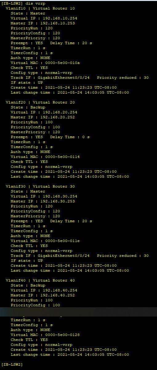
4.1、在ZB-LSW2很ZB-LSW3上分别执行display vrrp命令查看VRRP备份组的状态信息和配置参数
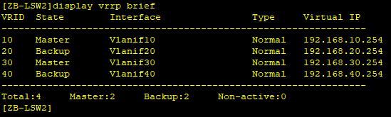
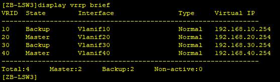
4.2、在ZB-LSW2和ZB-LSW3上分别执行display vrrp brief命令,查看VRRP 状态
#可以看到ZB-LSW2在备份组10、30中作为Master设备,在备份组20、40中作为Backup设备。
#可以看到ZB-LSW3在备份组20、40中作为Master设备,在备份组10、30中作为Backup设备。
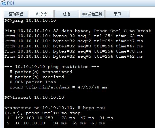
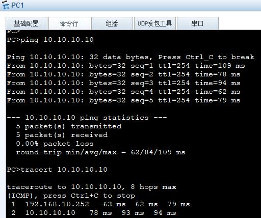
4.3、在PC1、PC2上分别ping AR1的环回口10.10.10.10及追踪路径
#可知PC1访问10.10.10.10的数据流量是通过ZB-LSW2转发的。
#可知PC2访问10.10.10.10的数据流量是通过ZB-LSW3转发的。

链路故障模拟测试
1、测试ZB-LSW2与ZB-LSW4之间连接链路故障时,MSTP的端口角色切换情况
#模拟在ZB-LSW4上将instance 1的根端口GE0/0/1关闭时,堵塞端口GE0/0/2会启用成为根端口。
2、测试ZB-LSW2与AR1之间连接链路故障时,VRRP的切换
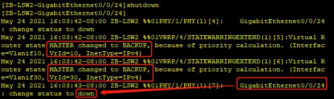
2.1、在交换机ZB-LSW2上关闭上行链路GE0/0/24口,模拟上行链路出现故障之后,VRRP备份组切换情况。
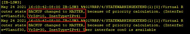
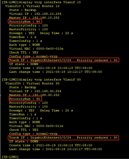
#可以看到VRRP开始切换2.2、在ZB-LSW2执行display vrrp interface vlanif 10、display vrrp interface vlanif 30命令查看备份组10、30的状态信息。
#ZB-LSW2备份组10与备份组30的优先级降低了30,成为了Backup设备;ZB-LSW3成为了备份组10、备份组30的Master设备。
#ZB-LSW2作为备份组10和备份组30的Master设备,当其上行接口或直连链路发生障时,通过调整自身优先级,触发主备切换,确保流量正常转发。
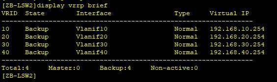
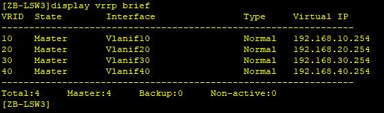
2.3、在ZB-LSW2和ZB-LSW3上分别执行display vrrp brief命令,查看VRRP 状态
2.4、在PC1上ping AR1的环回口10.10.10.10及追踪路径
#可知PC1访问10.10.10.10的数据流量是通过ZB-LSW3转发的。
配置文件
<AR1>dis cu
sysname AR1
#
interface GigabitEthernet0/0/1
 ip address 192.168.12.2 255.255.255.0
#
interface GigabitEthernet0/0/2
 ip address 192.168.13.2 255.255.255.0
#
interface LoopBack1
 ip address 10.10.10.10 255.255.255.255
#
ospf 10 router-id 1.1.1.1
 area 0.0.0.0
  network 10.10.10.10 0.0.0.0
  network 192.168.12.0 0.0.0.255
  network 192.168.13.0 0.0.0.255
#
<ZB-LSW2>dis cu
sysname ZB-LSW2
#
vlan batch 2 10 12 20 30 40
#
stp instance 1 root primary
stp instance 2 root secondary
#
stp region-configuration
 region-name ZB
 instance 1 vlan 10 30
 instance 2 vlan 20 40
 active region-configuration
#
interface Vlanif10
 ip address 192.168.10.253 255.255.255.0
 vrrp vrid 10 virtual-ip 192.168.10.254
 vrrp vrid 10 priority 120
 vrrp vrid 10 preempt-mode timer delay 20
 vrrp vrid 10 track interface GigabitEthernet0/0/24 reduced 30
#
interface Vlanif12
 ip address 192.168.12.1 255.255.255.0
#
interface Vlanif20
 ip address 192.168.20.253 255.255.255.0
 vrrp vrid 20 virtual-ip 192.168.20.254
#
interface Vlanif30
 ip address 192.168.30.253 255.255.255.0
 vrrp vrid 30 virtual-ip 192.168.30.254
 vrrp vrid 30 priority 120
 vrrp vrid 30 preempt-mode timer delay 20
 vrrp vrid 30 track interface GigabitEthernet0/0/24 reduced 30
#
interface Vlanif40
 ip address 192.168.40.253 255.255.255.0
 vrrp vrid 40 virtual-ip 192.168.40.254
#
interface Eth-Trunk1
 port link-type trunk
 port trunk allow-pass vlan 2 to 50
#
interface GigabitEthernet0/0/11
 port link-type trunk
 port trunk allow-pass vlan 2 to 50
#
interface GigabitEthernet0/0/12
 port link-type trunk
 port trunk allow-pass vlan 2 to 50
#
interface GigabitEthernet0/0/13
 port link-type trunk
 port trunk allow-pass vlan 2 to 50
#
interface GigabitEthernet0/0/21
 eth-trunk 1
#
interface GigabitEthernet0/0/22
 eth-trunk 1
#
interface GigabitEthernet0/0/24
 port link-type access
 port default vlan 12
#
ospf 10 router-id 11.2.2.2
 area 0.0.0.0
  network 192.168.12.0 0.0.0.255
  network 192.168.10.0 0.0.0.255
  network 192.168.20.0 0.0.0.255
  network 192.168.30.0 0.0.0.255
  network 192.168.40.0 0.0.0.255
#
port-group 1
 group-member GigabitEthernet0/0/11
 group-member GigabitEthernet0/0/12
 group-member GigabitEthernet0/0/13
#
<ZB-LSW3>display current-configuration
sysname ZB-LSW3
#
vlan batch 3 10 13 20 30 40
#
stp instance 1 root secondary
stp instance 2 root primary
#
stp region-configuration
 region-name ZB
 instance 1 vlan 10 30
 instance 2 vlan 20 40
 active region-configuration
#
interface Vlanif10
 ip address 192.168.10.252 255.255.255.0
 vrrp vrid 10 virtual-ip 192.168.10.254
#
interface Vlanif13
 ip address 192.168.13.1 255.255.255.0
#
interface Vlanif20
 ip address 192.168.20.252 255.255.255.0
 vrrp vrid 20 virtual-ip 192.168.20.254
 vrrp vrid 20 priority 120
 vrrp vrid 20 preempt-mode timer delay 20
 vrrp vrid 20 track interface GigabitEthernet0/0/24 reduced 30
#
interface Vlanif30
 ip address 192.168.30.252 255.255.255.0
 vrrp vrid 30 virtual-ip 192.168.30.254
#
interface Vlanif40
 ip address 192.168.40.252 255.255.255.0
 vrrp vrid 40 virtual-ip 192.168.40.254
 vrrp vrid 40 priority 120
 vrrp vrid 40 preempt-mode timer delay 20
 vrrp vrid 40 track interface GigabitEthernet0/0/24 reduced 30
#
interface Eth-Trunk1
 port link-type trunk
 port trunk allow-pass vlan 2 to 50
#
interface GigabitEthernet0/0/11
 port link-type trunk
 port trunk allow-pass vlan 2 to 50
#
interface GigabitEthernet0/0/12
 port link-type trunk
 port trunk allow-pass vlan 2 to 50
#
interface GigabitEthernet0/0/13
 port link-type trunk
 port trunk allow-pass vlan 2 to 50
#
interface GigabitEthernet0/0/21
 eth-trunk 1
#
interface GigabitEthernet0/0/22
 eth-trunk 1
#
interface GigabitEthernet0/0/24
 port link-type access
 port default vlan 13
#
ospf 10 router-id 11.3.3.3
 area 0.0.0.0
  network 192.168.13.0 0.0.0.255
  network 192.168.10.0 0.0.0.255
  network 192.168.20.0 0.0.0.255
  network 192.168.30.0 0.0.0.255
  network 192.168.40.0 0.0.0.255
#
<ZB-LSW4>display current-configuration
sysname ZB-LSW4
#
vlan batch 10 20 30 40
#
stp bpdu-protection
#
stp region-configuration
 region-name ZB
 instance 1 vlan 10 30
 instance 2 vlan 20 40
 active region-configuration
#
interface Ethernet0/0/1
 port link-type access
 port default vlan 10
 stp edged-port enable
#
interface GigabitEthernet0/0/1
 port link-type trunk
 port trunk allow-pass vlan 2 to 50
#
interface GigabitEthernet0/0/2
 port link-type trunk
 port trunk allow-pass vlan 2 to 50
#
<ZB-LSW5>display current-configuration
sysname ZB-LSW5
#
undo info-center enable
#
vlan batch 10 20 30 40
#
stp bpdu-protection
#
stp region-configuration
 region-name ZB
 instance 1 vlan 10 30
 instance 2 vlan 20 40
 active region-configuration
#
interface Ethernet0/0/1
 port link-type access
 port default vlan 20
 stp edged-port enable
#
interface Ethernet0/0/6
 port link-type access
 port default vlan 30
 stp edged-port enable
#
interface GigabitEthernet0/0/1
 port link-type trunk
 port trunk allow-pass vlan 2 to 50
#
interface GigabitEthernet0/0/2
 port link-type trunk
 port trunk allow-pass vlan 2 to 50
#
<ZB-LSW6>display current-configuration
#
sysname ZB-LSW6
#
undo info-center enable
#
vlan batch 10 20 30 40
#
stp bpdu-protection
#
stp region-configuration
 region-name ZB
 instance 1 vlan 10 30
 instance 2 vlan 20 40
 active region-configuration
#
interface Ethernet0/0/1
 port link-type access
 port default vlan 40
 stp edged-port enable
#
interface GigabitEthernet0/0/1
 port link-type trunk
 port trunk allow-pass vlan 2 to 50
#
interface GigabitEthernet0/0/2
 port link-type trunk
 port trunk allow-pass vlan 2 to 50
#
作者: 庞德芬
排版: 何颖连
审核: 大元帅府码头

点击下方“正月十六工作室”查看更多学习资源
以上是关于企业内部网络的多出口相互冗余备份与负载均衡的主要内容,如果未能解决你的问题,请参考以下文章