配置静态路由和默认路由!
Posted handsomeboy-东
tags:
篇首语:本文由小常识网(cha138.com)小编为大家整理,主要介绍了配置静态路由和默认路由!相关的知识,希望对你有一定的参考价值。
文章目录
一、静态路由
1.1静态路由的特点
静态路由是由管理员手动配置的,是单向的,能对路由的行为进行精准的控制,但是缺乏灵活性(路由器数量庞大时,会大大增加管理员的工作负担)
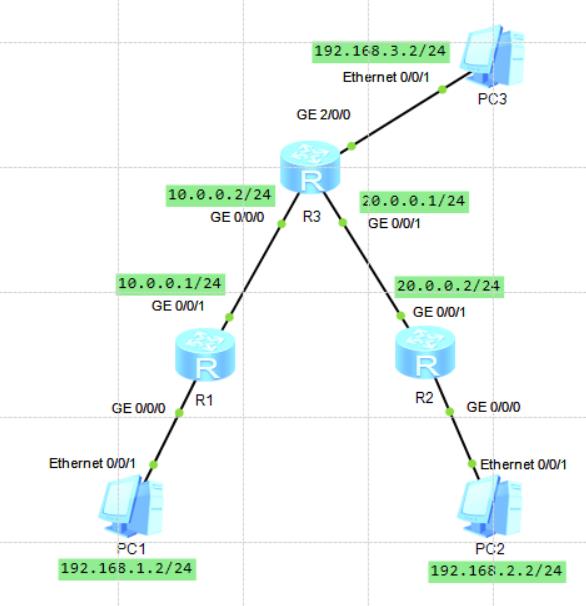
1.2静态路由的配置实验
图一:

**
1)分别配置好PC1、PC2和PC3的IP地址,子网掩码和网关
2)分别配置R1、R2和R3的接口ip**
- R1:
[Huawei]sys
[Huawei]sysname R1
[R1]int
[R1]interface g0/0/0
[R1-GigabitEthernet0/0/0]ip add
[R1-GigabitEthernet0/0/0]ip address 192.168.1.1 24
[R1-GigabitEthernet0/0/0]
Apr  4 2021 14:30:40-08:00 R1 %%01IFNET/4/LINK_STATE(l)[0]:The line protocol IP
on the interface GigabitEthernet0/0/0 has entered the UP state.
[R1-GigabitEthernet0/0/0]interface g0/0/1
[R1-GigabitEthernet0/0/1]ip address 10.0.0.1 24
Apr  4 2021 14:31:20-08:00 R1 %%01IFNET/4/LINK_STATE(l)[1]:The line protocol IP
on the interface GigabitEthernet0/0/1 has entered the UP state.
[R1-GigabitEthernet0/0/1]
- R2:
<Huawei>sys
<Huawei>system-view
Enter system view, return user view with Ctrl+Z.
[Huawei]sys
[Huawei]sysname R2
[R2]int
[R2]interface g0/0/0
[R2-GigabitEthernet0/0/0]ip address 192.168.2.1 24
Apr  4 2021 14:34:02-08:00 R2 %%01IFNET/4/LINK_STATE(l)[0]:The line protocol IP
on the interface GigabitEthernet0/0/0 has entered the UP state.
[R2-GigabitEthernet0/0/0]interface g0/0/1
[R2-GigabitEthernet0/0/1]ip address 20.0.0.2 24
Apr  4 2021 14:34:33-08:00 R2 %%01IFNET/4/LINK_STATE(l)[1]:The line protocol IP
on the interface GigabitEthernet0/0/1 has entered the UP state.
[R2-GigabitEthernet0/0/1]
- R3:
[Huawei]sys
[Huawei]sysname R3
[R3]int
[R3]interface g0/0/0
[R3-GigabitEthernet0/0/0]ip address 10.0.0.2 24
Apr  4 2021 14:38:46-08:00 R3 %%01IFNET/4/LINK_STATE(l)[0]:The line protocol IP
on the interface GigabitEthernet0/0/0 has entered the UP state.
[R3-GigabitEthernet0/0/0]interface g0/0/1
[R3-GigabitEthernet0/0/1]ip address 20.0.0.1 24
Apr  4 2021 14:39:04-08:00 R3 %%01IFNET/4/LINK_STATE(l)[1]:The line protocol IP
on the interface GigabitEthernet0/0/1 has entered the UP state.
[R3-GigabitEthernet0/0/1]interface g2/0/0
[R3-GigabitEthernet2/0/0]ip address 192.168.3.1 24
[R3-GigabitEthernet2/0/0]
Apr  4 2021 14:39:30-08:00 R3 %%01IFNET/4/LINK_STATE(l)[2]:The line protocol IP
on the interface GigabitEthernet2/0/0 has entered the UP state.
[R3-GigabitEthernet2/0/0]
3)在R1上添加静态路由,可以用display ip routing-table命令查看自己的路由表
[R1]ip route-static 192.168.3.0 24 10.0.0.2
[R1]ip route-static 20.0.0.0 24 10.0.0.2
[R1]ip route-static 192.168.2.0 24 10.0.0.2
[R1]display  ip routing-table
Route Flags: R - relay, D - download to fib
------------------------------------------------------------------------------
Routing Tables: Public
         Destinations : 13       Routes : 13

Destination/Mask    Proto   Pre  Cost      Flags NextHop         Interface

       10.0.0.0/24  Direct  0    0           D   10.0.0.1        GigabitEthernet
0/0/1
       10.0.0.1/32  Direct  0    0           D   127.0.0.1       GigabitEthernet
0/0/1
     10.0.0.255/32  Direct  0    0           D   127.0.0.1       GigabitEthernet
0/0/1
       20.0.0.0/24  Static  60   0          RD   10.0.0.2        GigabitEthernet
0/0/1
      127.0.0.0/8   Direct  0    0           D   127.0.0.1       InLoopBack0
      127.0.0.1/32  Direct  0    0           D   127.0.0.1       InLoopBack0
127.255.255.255/32  Direct  0    0           D   127.0.0.1       InLoopBack0
    192.168.1.0/24  Direct  0    0           D   192.168.1.1     GigabitEthernet
0/0/0
    192.168.1.1/32  Direct  0    0           D   127.0.0.1       GigabitEthernet
0/0/0
  192.168.1.255/32  Direct  0    0           D   127.0.0.1       GigabitEthernet
0/0/0
    192.168.2.0/24  Static  60   0          RD   10.0.0.2        GigabitEthernet
0/0/1
    192.168.3.0/24  Static  60   0          RD   10.0.0.2        GigabitEthernet
0/0/1
255.255.255.255/32  Direct  0    0           D   127.0.0.1       InLoopBack0
4)同样方法的在R2,R3上添加静态路由
[R2]ip route-static 192.168.3.0 24 20.0.0.1
[R2]ip route-static 192.168.1.0 24 20.0.0.1
[R2]ip route-static 10.0.0.0 24 20.0.0.1
[R3]ip route-static 192.168.1.0 24 10.0.0.1
[R3]ip route-static 192.168.2.0 24 20.0.0.2
5)在PC1上pingPC2为通信状态,以此逐渐pingPC1和PC3,PC2和PC3
PC>ping 192.168.3.2

Ping 192.168.3.2: 32 data bytes, Press Ctrl_C to break
Request timeout!
Request timeout!
From 192.168.3.2: bytes=32 seq=3 ttl=126 time<1 ms
From 192.168.3.2: bytes=32 seq=4 ttl=126 time<1 ms
From 192.168.3.2: bytes=32 seq=5 ttl=126 time=16 ms
实验结果:PC1,PC2和PC3之间全部互通
二、默认路由
2.1默认路由的特点
默认路由是一种特殊的静态路由,当存在末梢网络时,默认路由会很大程度的降低管理员配置大量路由器时的工作负担
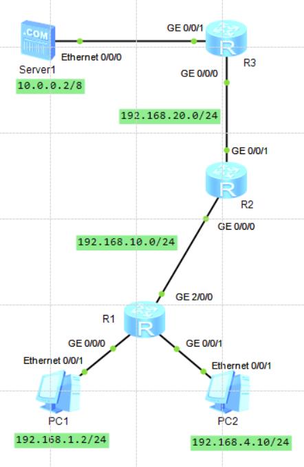
末梢网络:只有一个唯一的路径能够到达其它网络,如图二的PC1,PC2和R1之间的网络
2.2默认路由的配置实验
图二:

1)配置好PC1、PC2和Server1的IP地址
2)分别配置好路由器R1、R2和R3接口的IP地址
R1:
[R1-GigabitEthernet0/0/0]ip address 192.168.1.1 24
Apr  4 2021 16:35:13-08:00 R1 %%01IFNET/4/LINK_STATE(l)[0]:The line protocol IP
on the interface GigabitEthernet0/0/0 has entered the UP state.
[R1-GigabitEthernet0/0/0]interface g0/0/1
[R1-GigabitEthernet0/0/1]ip address 192.168.4.1 24
[R1-GigabitEthernet0/0/1]
Apr  4 2021 16:35:42-08:00 R1 %%01IFNET/4/LINK_STATE(l)[1]:The line protocol IP
on the interface GigabitEthernet0/0/1 has entered the UP state.
[R1-GigabitEthernet0/0/1]interface g2/0/0
[R1-GigabitEthernet2/0/0]ip address 192.168.10.1 24
[R1-GigabitEthernet2/0/0]
Apr  4 2021 16:39:49-08:00 R1 %%01IFNET/4/LINK_STATE(l)[2]:The line protocol IP
on the interface GigabitEthernet2/0/0 has entered the UP state.
R2:
[R2-GigabitEthernet0/0/0]ip address 192.168.10.2 24
Apr  4 2021 16:43:44-08:00 R2 %%01IFNET/4/LINK_STATE(l)[0]:The line protocol IP
on the interface GigabitEthernet0/0/0 has entered the UP state.
[R2-GigabitEthernet0/0/0]interface g0/0/1
[R2-GigabitEthernet0/0/1]
[R2-GigabitEthernet0/0/1]ip address 192.168.20.1 24
Apr  4 2021 16:44:24-08:00 R2 %%01IFNET/4/LINK_STATE(l)[1]:The line protocol IP
on the interface GigabitEthernet0/0/1 has entered the UP state.
R3:
[R3-GigabitEthernet0/0/0]ip address 192.168.20.2 24
Apr  4 2021 16:46:24-08:00 R3 %%01IFNET/4/LINK_STATE(l)[0]:The line protocol IP
on the interface GigabitEthernet0/0/0 has entered the UP state.
[R3-GigabitEthernet0/0/0]interface g0/0/1
[R3-GigabitEthernet0/0/1]ip address 10.0.0.1 255.0.0.0
Apr  4 2021 16:47:09-08:00 R3 %%01IFNET/4/LINK_STATE(l)[1]:The line protocol IP
on the interface GigabitEthernet0/0/1 has entered the UP state.
3)在R1上配置默认路由
[R1]ip route-static 0.0.0.0 0.0.0.0 192.168.10.2
4)在R2上配置静态路由
[R2]ip route-static 192.168.1.0 24 192.168.10.1
[R2]ip route-static 192.168.4.0 24 192.168.10.1
[R2]ip route-static 10.0.0.0 255.0.0.0 192.168.20.2
5)在R3上配置静态路由
[R3]ip route-static 192.168.1.0 24 192.168.20.1
[R3]ip route-static 192.168.4.0 24 192.168.20.1
[R3]ip route-static 192.168.10.0 24 192.168.20.1
6)在PC1上ping通Server1,在PC2上ping通Server1
PC1:
PC>ping 10.0.0.2

Ping 10.0.0.2: 32 data bytes, Press Ctrl_C to break
Request timeout!
Request timeout!
Request timeout!
From 10.0.0.2: bytes=32 seq=4 ttl=252 time=31 ms
From 10.0.0.2: bytes=32 seq=5 ttl=252 time=31 ms

--- 10.0.0.2 ping statistics ---
  5 packet(s) transmitted
  2 packet(s) received
  60.00% packet loss
  round-trip min/avg/max = 0/31/31 ms
PC2:
PC>ping 10.0.0.2

Ping 10.0.0.2: 32 data bytes, Press Ctrl_C to break
From 10.0.0.2: bytes=32 seq=1 ttl=252 time=31 ms
From 10.0.0.2: bytes=32 seq=2 ttl=252 time=32 ms
From 10.0.0.2: bytes=32 seq=3 ttl=252 time=31 ms
From 10.0.0.2: bytes=32 seq=4 ttl=252 time=31 ms
From 10.0.0.2: bytes=32 seq=5 ttl=252 time=16 ms

--- 10.0.0.2 ping statistics ---
  5 packet(s) transmitted
  5 packet(s) received
  0.00% packet loss
  round-trip min/avg/max = 16/28/32 ms
实验结果:图二中全网互通
以上是关于配置静态路由和默认路由!的主要内容,如果未能解决你的问题,请参考以下文章