cadence allegro 16.6 PCB:save design to another name or contact user to remove their lock
Posted
tags:
篇首语:本文由小常识网(cha138.com)小编为大家整理,主要介绍了cadence allegro 16.6 PCB:save design to another name or contact user to remove their lock相关的知识,希望对你有一定的参考价值。
昨晚保存的文件今天一开编辑之后就无法保存了。
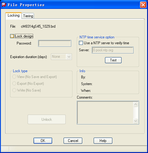
file "xxx.brd" is being edited by user "xxx" on date "ddd-mmm-yyy" on system "xxx".save design to another name or contact user to remove their lock.
unlock 图标是灰色的,how to remove the lock:
Cadence每日一学_13 | 使用 Allegro 制作PCB封装(以STM32为例)
文章目录
一、数据手册分析
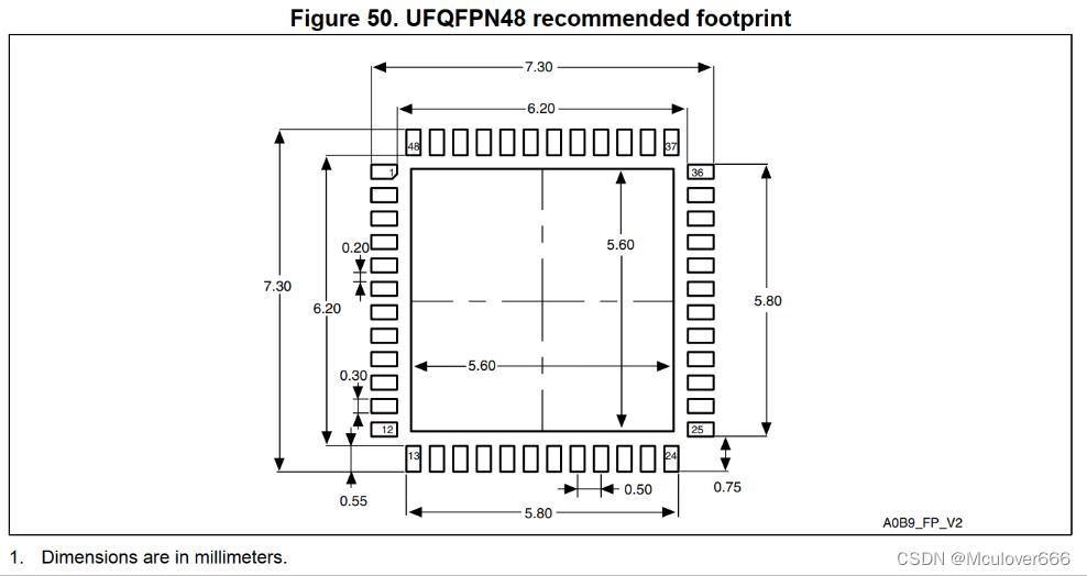
- 焊盘长度:理论值(7.3-6.2)/2 = 0.55,实际值为了焊接一般会大一点,1.2mm(48mil)
- 焊盘宽度:0.30(12mil)
- 焊盘间距:0.5
- 最远的焊盘中心离芯片中心点垂直位置:(6.2/2)+0.6=3.7mm
- 最远的焊盘中心离芯片中心点水平位置:2.75mm
二、新建封装文件
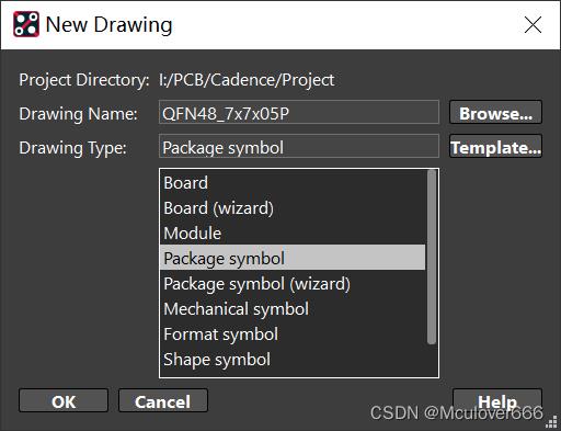
Step1. 新建Package Symbol
Step2. 设置设计参数
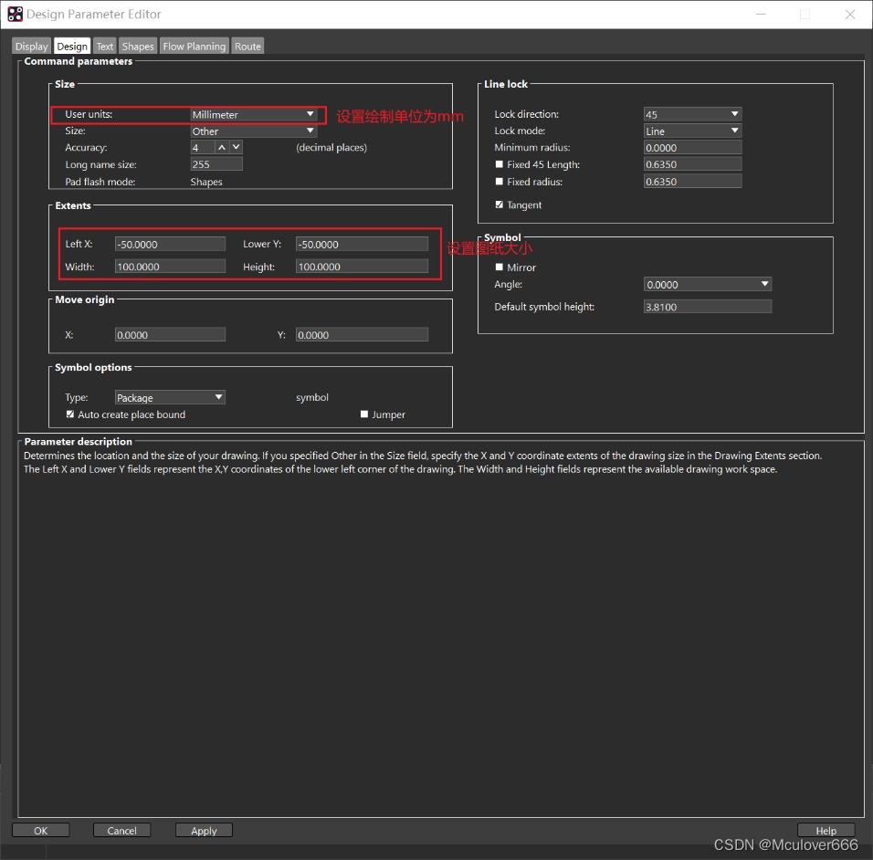
点击Setup->Design Parameter进行设置:
Step3. 设置焊盘路径
点击Steup->User Preferences:
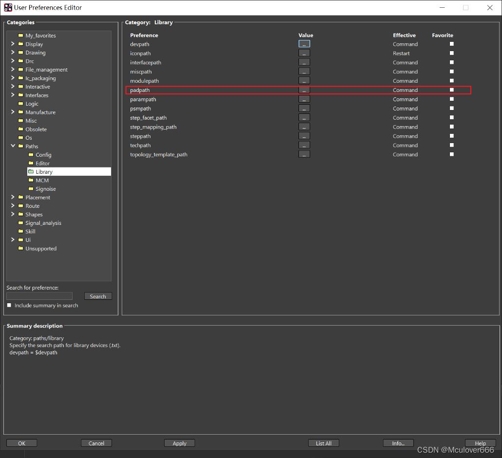
三、放置焊盘
点击 Layout->Pins放置焊盘。
设置焊盘参数:

使用命令设置起始点:
x -2.75 y -3.7
同样的方法放置其它三边:
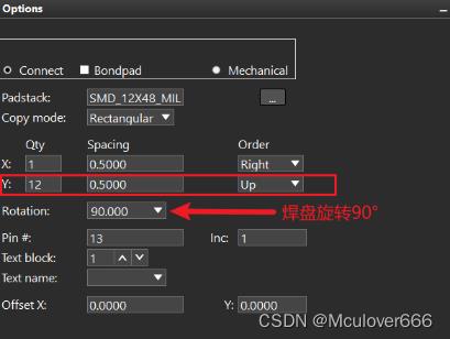
x 3.7 y -2.75

x 2.75 y 3.7
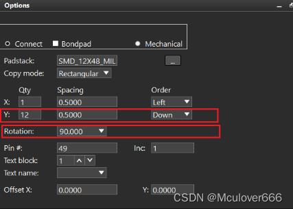
x -3.7 y 2.75
最后放置中心焊盘:

四、绘制Place Bound Top
该层是表示器件的最大范围。
点击 Add-> Rectangle,选择Subclass为Place Bound Top:

因为栅格的原因,放置出来的矩形太大了:
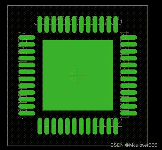
点击Setup -> Grid 调整栅格大小:
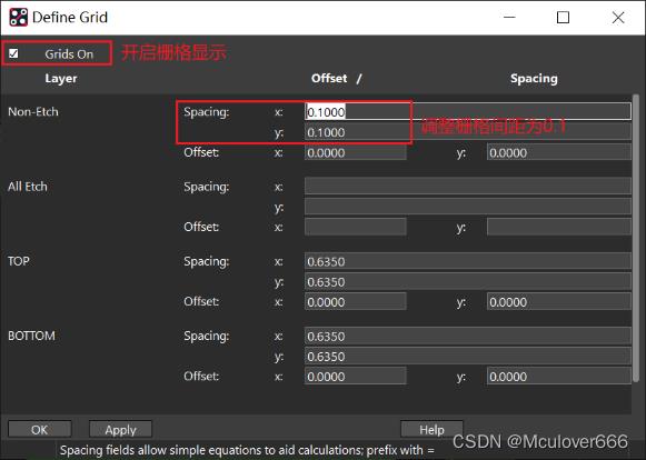
重新绘制矩形:
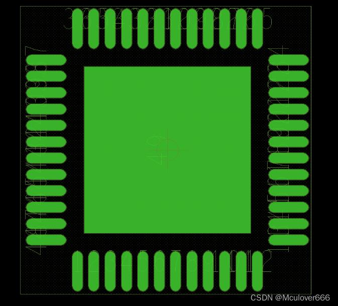
五、绘制装配层
点击Add->Line,选择绘制在装配层Assembly_Top:
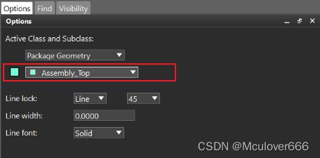

六、绘制丝印
1. 添加芯片边框丝印
点击Add->Line,设置线宽为5mil(0.127mm):

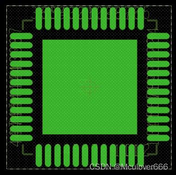
2. 添加1脚标识
绘制1脚的小圆点,点击Add->Circle:

x -2.75 y -4.65
ix 0.25
以同样的方法,在装配层也画同样大小的一个圆:

3. 添加芯片位号标识
点击 Layout->Labels->RefDes,选择在丝印层放置:
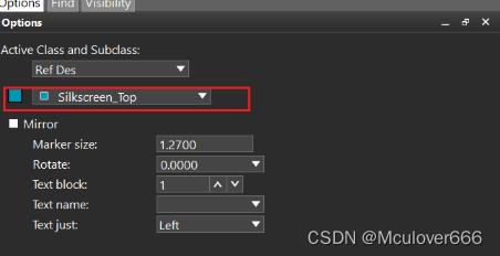
点击要放置的位置,输入U*。
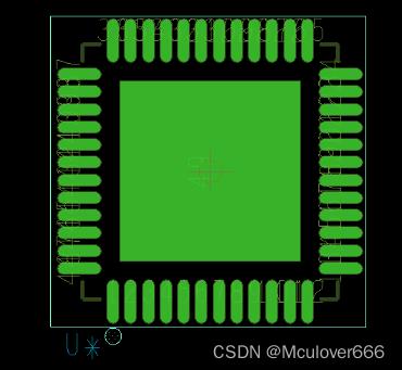
至此,STM32F411CEU6封装绘制完成:
以上是关于cadence allegro 16.6 PCB:save design to another name or contact user to remove their lock的主要内容,如果未能解决你的问题,请参考以下文章
cadence 16.6版本,在原理图中想添加room属性,编辑元件属性,在filter by里找不到cadence-allegro选项?
cadence allegro 16.6 PCB:save design to another name or contact user to remove their lock