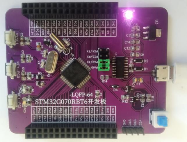
STM32G070RBT6基于Arduino框架下点灯程序
Posted perseverance52
tags:
篇首语:本文由小常识网(cha138.com)小编为大家整理,主要介绍了STM32G070RBT6基于Arduino框架下点灯程序相关的知识,希望对你有一定的参考价值。
STM32G070RBT6基于Arduino框架下点灯程序
✨说明:Arduino STM32系列开发环境搭建不在本示例范围内。
自制成本不超过10块钱.
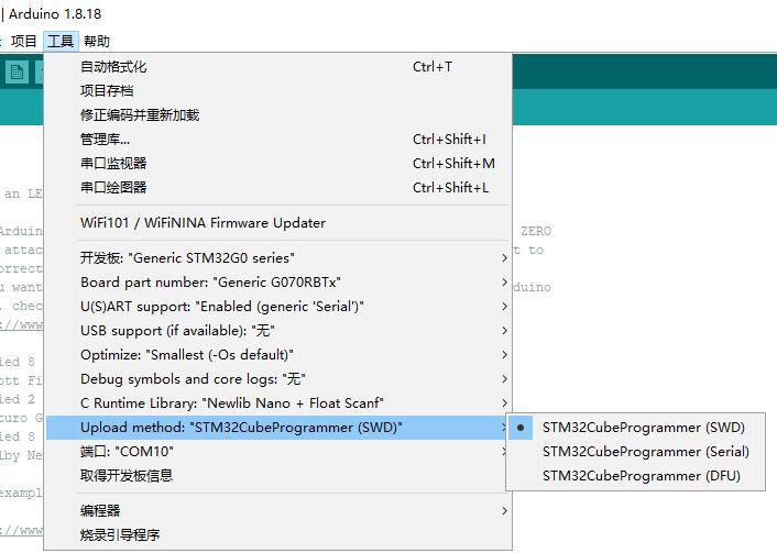
通过ST-Link烧录演示
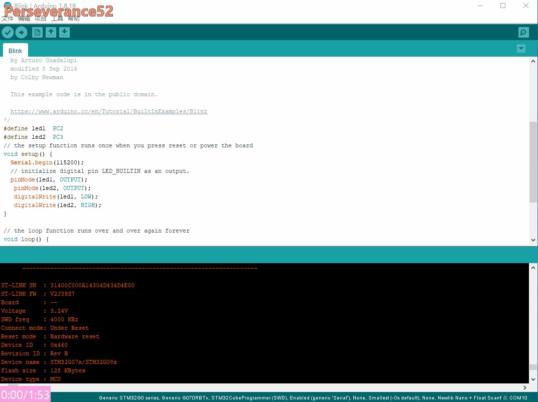
ST-Link下载Arduino IDE设置选项
通过串口下载
通过串口下载前提是已经设置好了
nBOOT_SEL和nBoot0默认勾选项去掉。
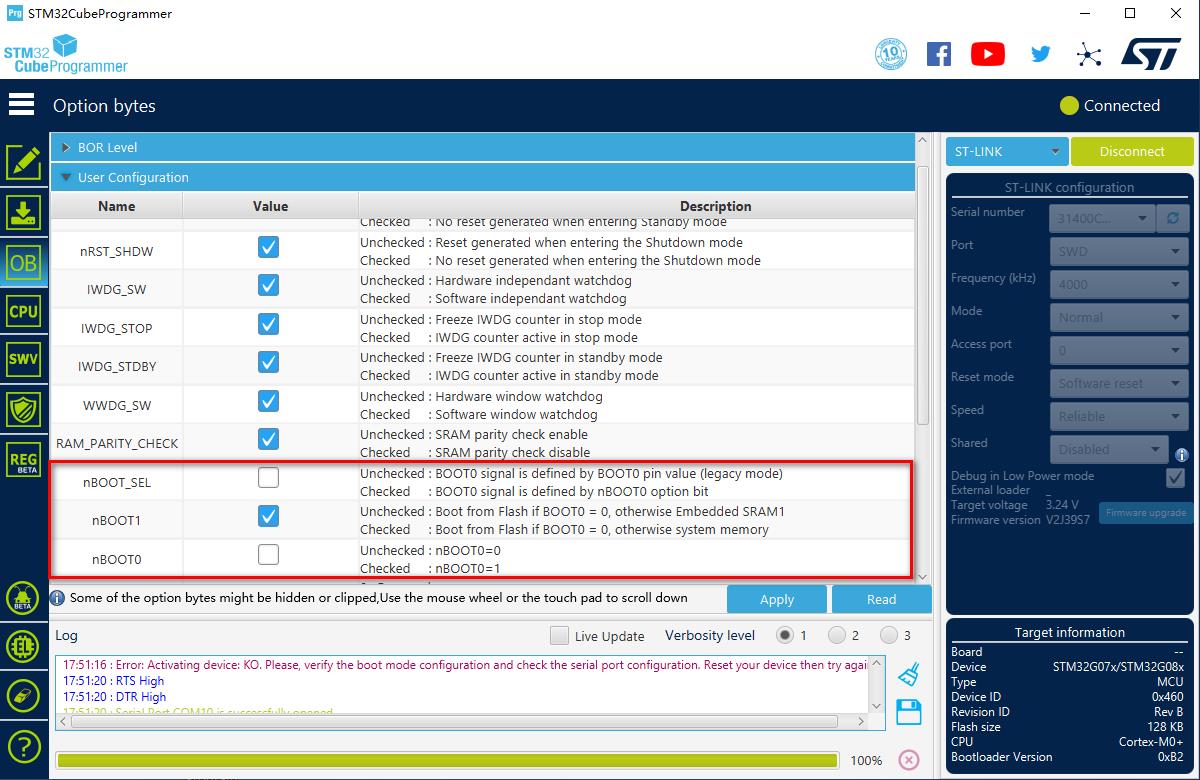
- 需要注意一点的是,通过串口下载有几率会下载失败的情况。需要重新按一下RST复位。
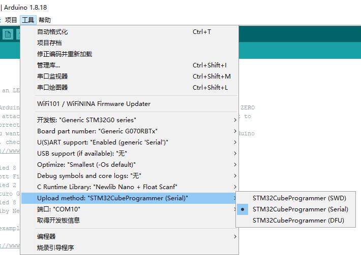
- 串口下载
Arduino IDE设置选项
修改串口1引脚
- 缺省的情况下,串口1是定义在PA1和PA0上的。将其修改到PA9和PA10上。
文件位置:
C:\\Users\\Administrator\\AppData\\Local\\Arduino15\\packages\\STMicroelectronics\\hardware\\stm32\\2.3.0\\variants\\STM32G0xx\\G070RBT\\variant_generic.h
// Default pin used for generic 'Serial' instance
// Mandatory for Firmata
#ifndef PIN_SERIAL_RX
  #define PIN_SERIAL_RX         PA10       //PA1
#endif
#ifndef PIN_SERIAL_TX
  #define PIN_SERIAL_TX         PA9       //PA0
#endif
引脚映射关系
/*----------------------------------------------------------------------------
 *        STM32 pins number
 *----------------------------------------------------------------------------*/
#define PA0                     PIN_A0
#define PA1                     PIN_A1
#define PA2                     PIN_A2
#define PA3                     PIN_A3
#define PA4                     PIN_A4
#define PA5                     PIN_A5
#define PA6                     PIN_A6
#define PA7                     PIN_A7
#define PA8                     8
#define PA9                     9
#define PA10                    10
#define PA11                    11
#define PA12                    12
#define PA13                    13
#define PA14                    14
#define PA15                    15
#define PB0                     PIN_A8
#define PB1                     PIN_A9
#define PB2                     PIN_A10
#define PB3                     19
#define PB4                     20
#define PB5                     21
#define PB6                     22
#define PB7                     23
#define PB8                     24
#define PB9                     25
#define PB10                    PIN_A11
#define PB11                    PIN_A12
#define PB12                    PIN_A13
#define PB13                    29
#define PB14                    30
#define PB15                    31
#define PC0                     32
#define PC1                     33
#define PC2                     34
#define PC3                     35
#define PC4                     PIN_A14
#define PC5                     PIN_A15
#define PC6                     38
#define PC7                     39
#define PC8                     40
#define PC9                     41
#define PC10                    42
#define PC11                    43
#define PC12                    44
#define PC13                    45
#define PC14                    46
#define PC15                    47
#define PD0                     48
#define PD1                     49
#define PD2                     50
#define PD3                     51
#define PD4                     52
#define PD5                     53
#define PD6                     54
#define PD8                     55
#define PD9                     56
#define PF0                     57
#define PF1                     58
#define PA9_R                   59
#define PA10_R                  60
示例程序
/*
  Blink

  Turns an LED on for one second, then off for one second, repeatedly.

  Most Arduinos have an on-board LED you can control. On the UNO, MEGA and ZERO
  it is attached to digital pin 13, on MKR1000 on pin 6. LED_BUILTIN is set to
  the correct LED pin independent of which board is used.
  If you want to know what pin the on-board LED is connected to on your Arduino
  model, check the Technical Specs of your board at:
  https://www.arduino.cc/en/Main/Products

  modified 8 May 2014
  by Scott Fitzgerald
  modified 2 Sep 2016
  by Arturo Guadalupi
  modified 8 Sep 2016
  by Colby Newman

  This example code is in the public domain.

  https://www.arduino.cc/en/Tutorial/BuiltInExamples/Blink
*/
#define led1  PC2
#define led2  PC3
// the setup function runs once when you press reset or power the board
void setup()
  Serial.begin(115200);
  // initialize digital pin LED_BUILTIN as an output.
  pinMode(led1, OUTPUT);
   pinMode(led2, OUTPUT);
   digitalWrite(led1, LOW);
   digitalWrite(led2, HIGH);


// the loop function runs over and over again forever
void loop()
  digitalWrite(led1, HIGH);   // turn the LED on (HIGH is the voltage level)
  digitalWrite(led2, LOW);
  delay(1000);                       // wait for a second
  Serial.println("Perseverance51");
  digitalWrite(led1, LOW);    // turn the LED off by making the voltage LOW
  digitalWrite(led2, HIGH);
  delay(1000);                       // wait for a second
  Serial.println("Arduino STM32G070RBT6");
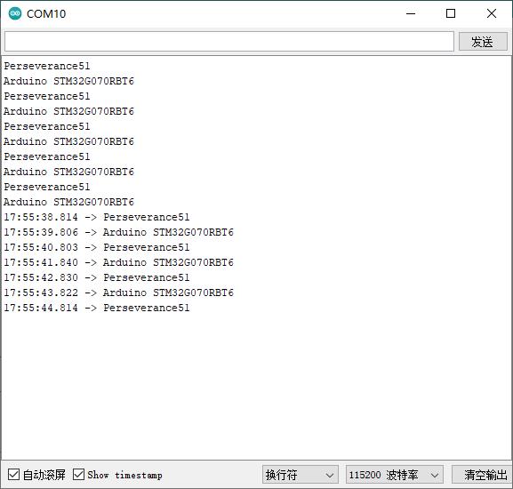
- 串口打印
以上是关于STM32G070RBT6基于Arduino框架下点灯程序的主要内容,如果未能解决你的问题,请参考以下文章
STM32G070RBT6基于Arduino框架下串口数据接收使用示例
STM32G070RBT6基于Arduino框架下eeprom使用示例
STM32G070RBT6基于Arduino框架ADC输入电压检测
