ROS中利用V-rep进行地图构建仿真
Posted
tags:
篇首语:本文由小常识网(cha138.com)小编为大家整理,主要介绍了ROS中利用V-rep进行地图构建仿真相关的知识,希望对你有一定的参考价值。
V-rep中显示激光扫描点
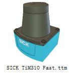
在VREP自带的场景中找到practicalPathPlanningDemo.ttt文件,删除场景中多余的物体只保留静态的地图。然后在Model browser→components→sensors中找到SICK TiM310 Fast激光雷达,拖入场景中:
打开脚本参数修改器,可以修改雷达扫描范围(默认为270°),是否显示雷达扫描线(true),以及最大探测距离(默认为4m)这三个参数。地图大小为5m×5m,我们将雷达最大探测距离改为2m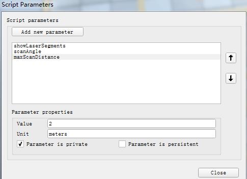
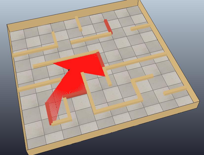
将激光雷达放到地图中任意位置,点击仿真按钮可以看到扫描光线(如果电脑比较卡可以将showLaserSegments这个参数设为false,就不会显示扫描线)如下图所示:
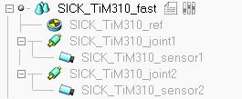
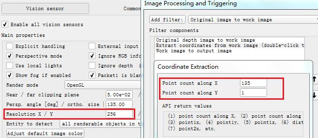
SICK_TiM310激光雷达在V-rep中是由两个视角为135°的视觉传感器模拟的,这两个视觉传感器可以探测深度信息:
双击视觉传感器图标,修改Filter中Coordinate Extraction的参数与传感器X/Y方向分辨率一致。X方向默认值为135,即会返回135个数据点,这里要改为256。
我们可以在V-rep中绘制出激光扫描图:在场景中添加一个Graph,将其设为显示处理(Explicit handling),然后添加用户自定义数据x和y:

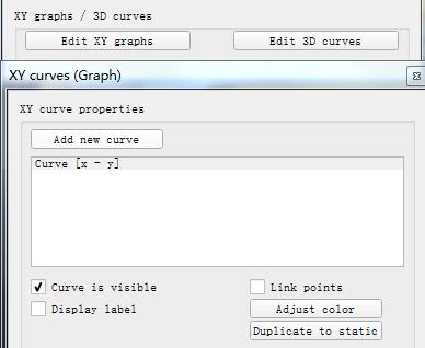
然后点击Edit XY graphs按钮,在弹出的对话框中添加一个新的曲线。X-value选择我们之前自定义的数据x,Y-value选择自定义的数据y,并去掉Link points选项:
将SICK_TiM310_fast的lua脚本代码修改如下:

if (sim_call_type==sim_childscriptcall_initialization) then
    visionSensor1Handle=simGetObjectHandle("SICK_TiM310_sensor1")
    visionSensor2Handle=simGetObjectHandle("SICK_TiM310_sensor2")
    joint1Handle=simGetObjectHandle("SICK_TiM310_joint1")
    joint2Handle=simGetObjectHandle("SICK_TiM310_joint2")
    sensorRefHandle=simGetObjectHandle("SICK_TiM310_ref")
    graphHandle = simGetObjectHandle("Graph")

    maxScanDistance=simGetScriptSimulationParameter(sim_handle_self,\'maxScanDistance\')
    if maxScanDistance>1000 then maxScanDistance=1000 end
    if maxScanDistance<0.1 then maxScanDistance=0.1 end
    simSetObjectFloatParameter(visionSensor1Handle,sim_visionfloatparam_far_clipping,maxScanDistance)
    simSetObjectFloatParameter(visionSensor2Handle,sim_visionfloatparam_far_clipping,maxScanDistance)
    maxScanDistance_=maxScanDistance*0.9999

    scanningAngle=simGetScriptSimulationParameter(sim_handle_self,\'scanAngle\')
    if scanningAngle>270 then scanningAngle=270 end
    if scanningAngle<2 then scanningAngle=2 end
    scanningAngle=scanningAngle*math.pi/180
    simSetObjectFloatParameter(visionSensor1Handle,sim_visionfloatparam_perspective_angle,scanningAngle/2)
    simSetObjectFloatParameter(visionSensor2Handle,sim_visionfloatparam_perspective_angle,scanningAngle/2)

    simSetJointPosition(joint1Handle,-scanningAngle/4)
    simSetJointPosition(joint2Handle,scanningAngle/4)
    red={1,0,0}
    lines=simAddDrawingObject(sim_drawing_lines,1,0,-1,1000,nil,nil,nil,red)

    if (simGetInt32Parameter(sim_intparam_program_version)<30004) then
        simDisplayDialog("ERROR","This version of the SICK sensor is only supported from V-REP V3.0.4 and upwards.&&nMake sure to update your V-REP.",sim_dlgstyle_ok,false,nil,{0.8,0,0,0,0,0},{0.5,0,0,1,1,1})
    end
end


if (sim_call_type==sim_childscriptcall_cleanup) then
    simRemoveDrawingObject(lines)
    simResetGraph(graphHandle)
end


if (sim_call_type==sim_childscriptcall_sensing) then
    measuredData={}

    if notFirstHere then
        -- We skip the very first reading
        simAddDrawingObjectItem(lines,nil)
        showLines=simGetScriptSimulationParameter(sim_handle_self,\'showLaserSegments\')
        r,t1,u1=simReadVisionSensor(visionSensor1Handle)
        r,t2,u2=simReadVisionSensor(visionSensor2Handle)

        m1=simGetObjectMatrix(visionSensor1Handle,-1)
        m01=simGetInvertedMatrix(simGetObjectMatrix(sensorRefHandle,-1))
        m01=simMultiplyMatrices(m01,m1)
        m2=simGetObjectMatrix(visionSensor2Handle,-1)
        m02=simGetInvertedMatrix(simGetObjectMatrix(sensorRefHandle,-1))
        m02=simMultiplyMatrices(m02,m2)
        if u1 then
            p={0,0,0}
            p=simMultiplyVector(m1,p)
            t={p[1],p[2],p[3],0,0,0}
            for j=0,u1[2]-1,1 do
                for i=0,u1[1]-1,1 do
                    w=2+4*(j*u1[1]+i)
                    v1=u1[w+1]
                    v2=u1[w+2]
                    v3=u1[w+3]
                    v4=u1[w+4]
                    if (v4<maxScanDistance_) then
                        p={v1,v2,v3}
                        p=simMultiplyVector(m01,p)
                        table.insert(measuredData,p[1])
                        table.insert(measuredData,p[2])
                        table.insert(measuredData,p[3])
                    end
                    if showLines then
                        p={v1,v2,v3}
                        p=simMultiplyVector(m1,p)
                        t[4]=p[1]
                        t[5]=p[2]
                        t[6]=p[3]
                        simAddDrawingObjectItem(lines,t)
                    end
                end
            end
        end
        if u2 then
            p={0,0,0}
            p=simMultiplyVector(m2,p)
            t={p[1],p[2],p[3],0,0,0}
            for j=0,u2[2]-1,1 do
                for i=0,u2[1]-1,1 do
                    w=2+4*(j*u2[1]+i)
                    v1=u2[w+1]
                    v2=u2[w+2]
                    v3=u2[w+3]
                    v4=u2[w+4]
                    if (v4<maxScanDistance_) then
                        p={v1,v2,v3}
                        p=simMultiplyVector(m02,p)
                        table.insert(measuredData,p[1])
                        table.insert(measuredData,p[2])
                        table.insert(measuredData,p[3])
                    end
                    if showLines then
                        p={v1,v2,v3}
                        p=simMultiplyVector(m2,p)
                        t[4]=p[1]
                        t[5]=p[2]
                        t[6]=p[3]
                        simAddDrawingObjectItem(lines,t)
                    end
                end
            end
        end
    end
    notFirstHere=true

    --stringData = simPackFloatTable(measuredData) -- Packs a table of floating-point numbers into a string
    --simSetStringSignal("UserData", stringData)

    simResetGraph(graphHandle)
    for i=1,#measuredData/3,1 do
        simSetGraphUserData(graphHandle,\'x\',measuredData[3*(i-1)+1])
        simSetGraphUserData(graphHandle,\'y\',measuredData[3*(i-1)+2])
        simHandleGraph(graphHandle,0)
    end

end
点击仿真按钮,可以在X/Y graph窗口中看到激光扫描结果如下:
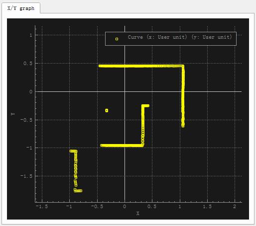
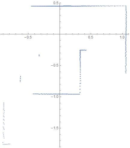
V-rep中的视觉传感器可以探测到障碍物的坐标以及与其距离,上面的X-Y图就是直接采用坐标点画出的。然而一般激光雷达只能探测障碍物距离,不能直接获取其坐标,我们可以将距离画成与角度对应的极坐标图。将距离数据保存为CSV文件,用Mathematica读入并画出极坐标图:
ranges = Flatten[Import["C:\\\\Users\\\\Administrator\\\\Desktop\\\\distance.csv"]];
ListPolarPlot[ranges, DataRange -> {-135 Degree, 135 Degree}]
发布LaserScan消息
下面的代码将激光雷达扫描数据按照LaserScan的消息格式发布出去:

if (sim_call_type==sim_childscriptcall_initialization) then
    visionSensor1Handle=simGetObjectHandle("SICK_TiM310_sensor1")
    visionSensor2Handle=simGetObjectHandle("SICK_TiM310_sensor2")
    joint1Handle=simGetObjectHandle("SICK_TiM310_joint1")
    joint2Handle=simGetObjectHandle("SICK_TiM310_joint2")
    sensorRefHandle=simGetObjectHandle("SICK_TiM310_ref")

    maxScanDistance=simGetScriptSimulationParameter(sim_handle_self,\'maxScanDistance\')
    if maxScanDistance>1000 then maxScanDistance=1000 end
    if maxScanDistance<0.1 then maxScanDistance=0.1 end
    simSetObjectFloatParameter(visionSensor1Handle,sim_visionfloatparam_far_clipping,maxScanDistance)
    simSetObjectFloatParameter(visionSensor2Handle,sim_visionfloatparam_far_clipping,maxScanDistance)
    maxScanDistance_=maxScanDistance*0.9999

    scanningAngle=simGetScriptSimulationParameter(sim_handle_self,\'scanAngle\')
    if scanningAngle>270 then scanningAngle=270 end
    if scanningAngle<2 then scanningAngle=2 end
    scanningAngle=scanningAngle*math.pi/180
    simSetObjectFloatParameter(visionSensor1Handle,sim_visionfloatparam_perspective_angle,scanningAngle/2)
    simSetObjectFloatParameter(visionSensor2Handle,sim_visionfloatparam_perspective_angle,scanningAngle/2)

    simSetJointPosition(joint1Handle,-scanningAngle/4)
    simSetJointPosition(joint2Handle,scanningAngle/4)
    red={1,0,0}
    lines=simAddDrawingObject(sim_drawing_lines,1,0,-1,1000,nil,nil,nil,red)

    if (simGetInt32Parameter(sim_intparam_program_version)<30004) then
        simDisplayDialog("ERROR","This version of the SICK sensor is only supported from V-REP V3.0.4 and upwards.&&nMake sure to update your V-REP.",sim_dlgstyle_ok,false,nil,{0.8,0,0,0,0,0},{0.5,0,0,1,1,1})
    end

    -- Enable an LaserScan publisher:
    pub = simExtRosInterface_advertise(\'/scan\', \'sensor_msgs/LaserScan\')
    --After calling this function, this publisher will treat uint8 arrays as string. Using strings should be in general much faster that using int arrays in Lua.
    simExtRosInterface_publisherTreatUInt8ArrayAsString(pub) -- treat uint8 arrays as strings (much faster, tables/arrays are kind of slow in Lua)

    angle_min= -135 * (math.pi/180);        -- angle correspond to FIRST beam in scan ( in rad)
    angle_max= 135 * (math.pi/180)          -- angle correspond to LAST beam in scan ( in rad)
    angle_increment = 270*(math.pi/180)/512 -- Angular resolution i.e angle between 2 beams

    -- sensor scans every 50ms with 512 beams. Each beam is measured in  (50 ms/ 512 )
    time_increment  = (1 / 20) / 512

    range_min = 0.05
    range_max = maxScanDistance -- scan can measure upto this range
end

if (sim_call_type==sim_childscriptcall_cleanup) then
    simRemoveDrawingObject(lines)
    simExtRosInterface_shutdownPublisher(pub)
end

if (sim_call_type==sim_childscriptcall_sensing) then
    measuredData={}
    distanceData={}

    if notFirstHere then
        -- We skip the very first reading
        simAddDrawingObjectItem(lines,nil)
        showLines=simGetScriptSimulationParameter(sim_handle_self,\'showLaserSegments\')
        r,t1,u1=simReadVisionSensor(visionSensor1Handle)
        r,t2,u2=simReadVisionSensor(visionSensor2Handle)

        m1=simGetObjectMatrix(visionSensor1Handle,-1)
        m01=simGetInvertedMatrix(simGetObjectMatrix(sensorRefHandle,-1))
        m01=simMultiplyMatrices(m01,m1)
        m2=simGetObjectMatrix(visionSensor2Handle,-1)
        m02=simGetInvertedMatrix(simGetObjectMatrix(sensorRefHandle,-1))
        m02=simMultiplyMatrices(m02,m2)
        if u1 then
            p={0,0,0}
            p=simMultiplyVector(m1,p)
            t={p[1],p[2],p[3],0,0,0}
            for j=0,u1[2]-1,1 do
                for i=0,u1[1]-1,1 do
                    w=2+4*(j*u1[1]+i)
                    v1=u1[w+1]
                    v2=u1[w+2]
                    v3=u1[w+3]
                    v4=u1[w+4]
                    table.insert(distanceData,v4)
                    if (v4<maxScanDistance_) then
                        p={v1,v2,v3}
                        p=simMultiplyVector(m01,p)
                        table.insert(measuredData,p[1])
                        table.insert(measuredData,p[2])
                        table.insert(measuredData,p[3])
                    end
                    if showLines then
                        p={v1,v2,v3}
                        p=simMultiplyVector(m1,p)
                        t[4]=p[1]
                        t[5]=p[2]
                        t[6]=p[3]
                        simAddDrawingObjectItem(lines,t)
                    end
                end
            end
        end
        if u2 then
            p={0,0,0}
            p=simMultiplyVector(m2,p)
            t={p[1],p[2],p[3],0,0,0}
            for j=0,u2[2]-1,1 do
                for i=0,u2[1]-1,1 do
                    w=2+4*(j*u2[1]+i)
                    v1=u2[w+1]
                    v2=u2[w+2]
                    v3=u2[w+3]
                    v4=u2[w+4]
                    table.insert(distanceData,v4)
                    if (v4<maxScanDistance_) then
                        p={v1,v2,v3}
                        p=simMultiplyVector(m02,p)
                        table.insert(measuredData,p[1])
                        table.insert(measuredData,p[2])
                        table.insert(measuredData,p[3])
                    end
                    if showLines then
                        p={v1,v2,v3}
                        p=simMultiplyVector(m2,p)
                        t[4]=p[1]
                        t[5]=p[2]
                        t[6]=p[3]
                        simAddDrawingObjectItem(lines,t)
                    end
                end
            end
        end
    end
    notFirstHere=true

    -- populate the LaserScan message
    scan={}
    scan[\'header\']={seq=0,stamp=simExtRosInterface_getTime(), frame_id="SICK_TiM310_ref"}
    scan[\'angle_min\']=angle_min
    scan[\'angle_max\']=angle_max
    scan[\'angle_increment\']=angle_increment
    scan[\'time_increment\']=time_increment
    scan[\'scan_time\']=simExtRosInterface_getTime() -- Return the current ROS time i.e. the time returned by ros::Time::now()
    scan[\'range_min\']=range_min
    scan[\'range_max\']=range_max
    scan[\'ranges\'] = distanceData
    scan[\'intensities\']={}

    simExtRosInterface_publish(pub, scan)
end
注意代码中发布的距离是相对于视觉传感器坐标系的,因为模型中视觉传感器坐标系与激光雷达坐标系(SICK_TiM310_ref)在X、Y方向的位置是一致的,而Z坐标只存在一点高度差异,并不会影响X-Y平面内障碍物相对于SICK_TiM310_ref参考坐标系的位置坐标。如果这两个坐标系在X、Y方向存在偏差,就需要将采集到的数据点转换到SICK_TiM310_ref坐标系中。
另外代码中变量v4为激光雷达探测到的距物体的距离,如果在最大扫描范围内没有探测到物体,则会返回最大值。由于这个距离与扫描角度是一一对应的,因此要注意table.insert函数的使用,不能放在下一句的if语句之中,否则在超过最大扫描范围的地方不会向列表内插入距离数据,这样会造成距离与角度不匹配,可能导致激光图像出现歪斜。
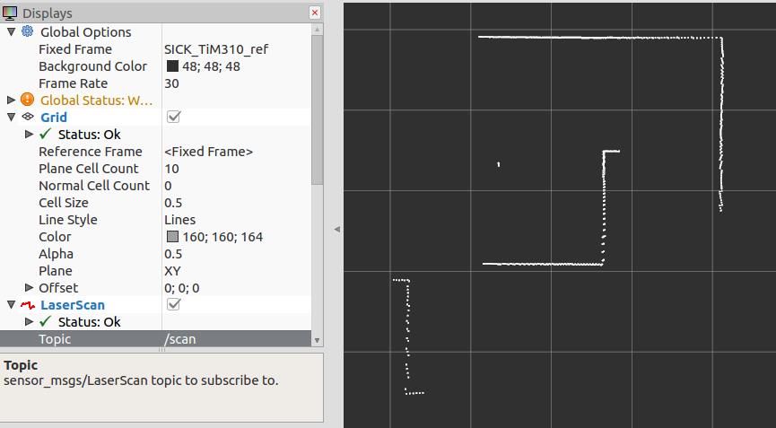
点击仿真按钮,程序运行没问题后在rviz中可以添加LaserScan进行查看:
输入rostopic hz /scan可以查看消息发布的频率:

这里有一个小问题,从上图可以看出激光雷达信息发布的频率约为43Hz,但是V-rep仿真的时间步长为50ms,消息发布的频率应该为20Hz。这是因为V-rep中默认情况下仿真并不是以实际时间在运行,在工具栏上点击real-time mode按钮,开始实时模式:

现在再查看消息发布的频率,可以看到频率和我们设定的一样了:

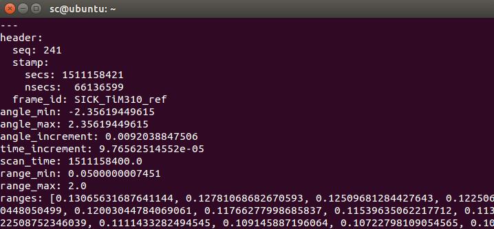
另外,通过rostopic echo /scan命令可以查看消息的具体内容(方便我们检查出可能存在的错误:我在虚拟机下运行得到的数据很奇怪,但是换到实体系统上就没有问题):
发布nav_msgs/Odometry里程计信息及tf变换
在V-rep中进行地图构建仿真时可以用键盘控制机器人的位置(这里直接简化为控制激光雷达),那么机器人相对于初始时刻odom坐标系的位置和姿态等信息可以通过航迹推算(使用里程计或惯性传感器根据机器人运动学模型计算)获得。然后需要将其按照nav_msgs/Odometry消息的格式包装好,发布到/odom话题上;并且还要发布机器人坐标系base_link相对于odom坐标系的tf变换。The nav_msgs/Odometry message stores an estimate of the position and velocity of a robot in free space. The "tf" software library is responsible for managing the relationships between coordinate frames relevant to the robot in a transform tree. Therefore, any odometry source must publish information about the coordinate frame that it manages.
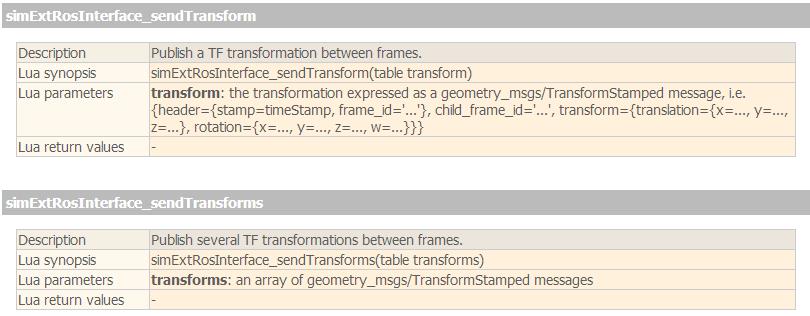
V-rep脚本中发布tf变换主要用下面这两个函数,区别在于simExtRosInterface_sendTransform调用一次只能发送一对变换,而simExtRosInterface_sendTransforms则可以一次发送多对变换,函数参数是变换的列表:
根据V-rep中物体的句柄和名称发布坐标系变换的代码如下:
function getTransformStamped(objHandle, name, relTo, relToName)
  -- This function retrieves the stamped transform for a specific object
  t = simExtRosInterface_getTime()
  p = simGetObjectPosition(objHandle, relTo)
  o = simGetObjectQuaternion(objHandle, relTo)
  return {
      header = {stamp=t, frame_id=relToName},
      child_frame_id = name,
      transform = {
        translation={x=p[1],y=p[2],z=p[3]},
        rotation={x=o[1],y=o[2],z=o[3],w=o[4]}
              }
      }
end

----------------------------------------------------------------------------------------------------------------------
 simExtRosInterface_sendTransforms({getTransformStamped(sensorRefHandle,\'SICK_TiM310_ref\',baseLinkHandle,\'base_link\'),
                                      getTransformStamped(baseLinkHandle,\'base_link\',odomHandle,\'odom\')})
--simExtRosInterface_sendTransform(getTransformStamped(sensorRefHandle,\'SICK_TiM310_ref\',baseLinkHandle,\'base_link\')
--simExtRosInterface_sendTransform(getTransformStamped(baseLinkHandle,\'base_link\',odomHandle,\'odom\'))
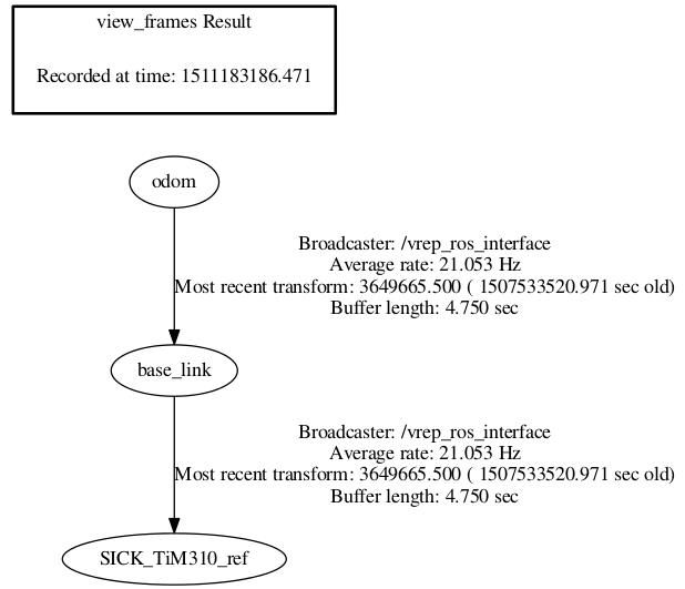
我们在V-rep的脚本程序中向ros系统发布了坐标系之间的变换,有时可能会出现许多错误。为了方便排查错误,ros提供了一系列tf调试工具。下面两种命令都可以以图形化的方式查看坐标系之间的tf关系:
$ rosrun tf view_frames
$ rosrun rqt_tf_tree rqt_tf_tree
打开生成的pdf文件或在弹出的rqt窗口中,可以很清楚的看出里程计坐标系odom,机器人坐标系base_link,以及激光雷达坐标系SICK_TiM310_ref之间的关系:
tf_echo命令可以用于查看两个坐标系之间具体的变换关系(注意输出的是target_frame相对于reference_frame的关系):
$ rosrun tf tf_echo reference_frame target_frame
如下图所示,会输出激光传感器坐标系SICK_TiM310_ref相对于机器人坐标系base_link的变换(V-rep模型中这两个坐标系是重合的):

在/odom话题上发布nav_msgs/Odometry消息的代码如下(注意这里直接调用函数获取到相对于odom的位置和姿态,省去了航迹推算的过程。如果在真实的小车上进行测试,就需要根据里程计数据来推算小车的位置和姿态等信息,然后再发送出去):
odomPub = simExtRosInterface_advertise(\'/odom\', \'nav_msgs/Odometry\')

local pos = simGetObjectPosition(baseLinkHandle,  odomHandle)
local ori = simGetObjectQuaternion(baseLinkHandle, odomHandle)

odom = {}
odom.header = {seq=0,stamp=simExtRosInterface_getTime(), frame_id="odom"}
odom.child_frame_id = \'base_link\'
odom.pose = { pose={position={x=pos[1],y=pos[2],z=pos[3]}, orientation={x=ori[1],y=ori[2],z=ori[3],w=ori[4]} } }

simExtRosInterface_publish(odomPub, odom)
使用gmapping构建地图
gmaping包是用来生成地图的,它需要从ROS系统监听多个Topic,并输出map。The slam_gmapping node takes in sensor_msgs/LaserScan messages and builds a map (nav_msgs/OccupancyGrid)
- Subscribed Topics:
- tf (tf/tfMessage):Transforms necessary to relate frames for laser, base, and odometry
- scan (sensor_msgs/LaserScan):Laser scans to create the map from
- Required tf Transforms:
- <the frame attached to incoming scans> → base_link:usually a fixed value, broadcast periodically by a robot_state_publisher, or a tf static_transform_publisher.
- base_link → odom:usually provided by the odometry system (e.g., the driver for the mobile base)
- Provided t
以上是关于ROS中利用V-rep进行地图构建仿真的主要内容,如果未能解决你的问题,请参考以下文章
