STM32的RFID射频读写控制装置
Posted KEKE
tags:
篇首语:本文由小常识网(cha138.com)小编为大家整理,主要介绍了STM32的RFID射频读写控制装置相关的知识,希望对你有一定的参考价值。
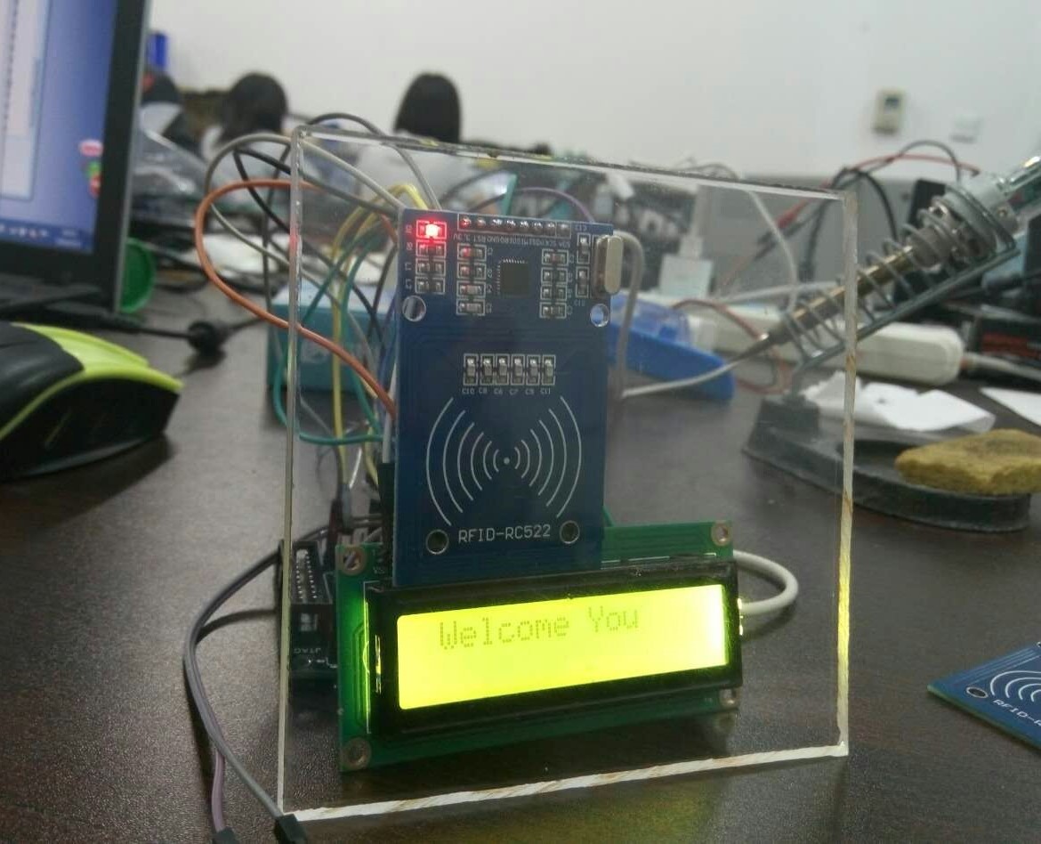
,大二上学期做的,过了很久,先上一下图:

这并不是做个最后一版;主体是RC552+STM32+1062;蜂鸣器,继电器,LED等;反正最后的效果就是,刷一下卡,1602显示一下持卡人(需要提前注册,注册方法也就是在数组里多添加几个编号,哈哈,毕竟没有数据库暂时也只能想到这样了);然后蜂鸣器响,灯亮,继电器开;
贴一下关键代码:
#include "delay.h"
#include "sys.h"
#include "usart.h"
#include "led.h"
#include "lcd1602.h"
#include "key.h"
#include <stdio.h>
#include "stm32f10x_gpio.h"
#include "stm32f10x_rcc.h"
#include "main.h"
#include "mfrc522.h"
#include "stm32f10x.h"
#include "exti.h"

 USART_InitTypeDef USART_InitStructure;

void GPIO_ini()
{
  GPIO_InitTypeDef  GPIO_InitStructure;

  /* Enable the GPIO Clock */
  RCC_APB2PeriphClockCmd(MF522_RST_CLK, ENABLE);

  /* Configure the GPIO pin */
  GPIO_InitStructure.GPIO_Pin = MF522_RST_PIN;
  GPIO_InitStructure.GPIO_Mode = GPIO_Mode_Out_PP;
  GPIO_InitStructure.GPIO_Speed = GPIO_Speed_2MHz;

  GPIO_Init(MF522_RST_PORT, &GPIO_InitStructure);

  /* Enable the GPIO Clock */
  RCC_APB2PeriphClockCmd(MF522_MISO_CLK, ENABLE);

  /* Configure the GPIO pin */
  GPIO_InitStructure.GPIO_Pin = MF522_MISO_PIN;
  GPIO_InitStructure.GPIO_Mode = GPIO_Mode_IN_FLOATING;
  GPIO_InitStructure.GPIO_Speed = GPIO_Speed_2MHz;

  GPIO_Init(MF522_MISO_PORT, &GPIO_InitStructure);

  /* Enable the GPIO Clock */
  RCC_APB2PeriphClockCmd(MF522_MOSI_CLK, ENABLE);

  /* Configure the GPIO pin */
  GPIO_InitStructure.GPIO_Pin = MF522_MOSI_PIN;
  GPIO_InitStructure.GPIO_Mode = GPIO_Mode_Out_PP;
  GPIO_InitStructure.GPIO_Speed = GPIO_Speed_2MHz;

  GPIO_Init(MF522_MOSI_PORT, &GPIO_InitStructure);

  /* Enable the GPIO Clock */
  RCC_APB2PeriphClockCmd(MF522_SCK_CLK, ENABLE);

  /* Configure the GPIO pin */
  GPIO_InitStructure.GPIO_Pin = MF522_SCK_PIN;
  GPIO_InitStructure.GPIO_Mode = GPIO_Mode_Out_PP;
  GPIO_InitStructure.GPIO_Speed = GPIO_Speed_2MHz;

  GPIO_Init(MF522_SCK_PORT, &GPIO_InitStructure);

  /* Enable the GPIO Clock */
  RCC_APB2PeriphClockCmd(MF522_NSS_CLK, ENABLE);

  /* Configure the GPIO pin */
  GPIO_InitStructure.GPIO_Pin = MF522_NSS_PIN;
  GPIO_InitStructure.GPIO_Mode = GPIO_Mode_Out_PP;
  GPIO_InitStructure.GPIO_Speed = GPIO_Speed_2MHz;

  GPIO_Init(MF522_NSS_PORT, &GPIO_InitStructure);

  /* Enable the GPIO Clock */
  RCC_APB2PeriphClockCmd(LED_CLK, ENABLE);

  /* Configure the GPIO pin */
  GPIO_InitStructure.GPIO_Pin = LED_PIN;
  GPIO_InitStructure.GPIO_Mode = GPIO_Mode_Out_PP;
  GPIO_InitStructure.GPIO_Speed = GPIO_Speed_2MHz;

  GPIO_Init(LED_PORT, &GPIO_InitStructure);
}

void InitializeSystem()
{
    //LED_OFF;
    delay_10ms(10);
    PcdReset();
    PcdAntennaOff();
    PcdAntennaOn();
    M500PcdConfigISOType( \'A\' );
    //LED_ON;
    delay_10ms(10);
    //LED_OFF;
    delay_10ms(10);
    //LED_ON;
    delay_10ms(10);
    //LED_OFF;
}
int main(void)
{

    char status;
    unsigned char snr, buf[16], TagType[2], SelectedSnr[4], DefaultKey[6] = {0xFF, 0xFF, 0xFF, 0xFF, 0xFF, 0xFF};
    u8 t;
    u8 str[] = "Jiaomengke";
    u8 str2[] = "Jiaomengke2";
    u8 str3[] = "Jiaomengke";

    delay_init();
    NVIC_Configuration();
    uart_init(9600);
    GPIO_Configuration();
    KEY_Init();
    LED_Init();
    flog:
    LCD1602_Init();
    //LCD1602_Show_Str(0, 0, "Please put card");
    LCD1602_Show_Str(1, 0, "    Please");
    LCD1602_Show_Str(2, 1, "  put card");
    GPIO_ini();
    InitializeSystem( );

    while(1)
    {        status= PcdRequest(REQ_ALL,TagType);
        if(!status)
        {
            status = PcdAnticoll(SelectedSnr);
            if(!status)
            {
                status=PcdSelect(SelectedSnr);
                if(!status)
                {
                    snr = 0;
                status = PcdAuthState(KEYA, (snr*4+3), DefaultKey, SelectedSnr);// УÑé0ÉÈÇøÃÜÂë
                    {
                        if(!status)
                        {
                            status = PcdRead((snr*4+1), buf);  //PcdWrite((snr*4+1), buf);    // ¶ÁÈ¡0ÉÈÇø1¿éÊý¾Ý
                            if(!status && (SelectedSnr[2]==0x3e||SelectedSnr[2]==0xf6||SelectedSnr[2]==0xf4||SelectedSnr[2]==0xe7))
                            {
                                LED_ON;
                                WaitCardOff();
                                while(1)
                                {  LCD1602_ClearScreen();
                                    LCD1602_Show_Str(1, 0, " Welcome You");
                                    if(SelectedSnr[2]==0x3e)
                                    LCD1602_Show_Str(2, 1, str);
                                    if(SelectedSnr[2]==0xf6)
                                    LCD1602_Show_Str(2, 1, str1);
                                    if(SelectedSnr[2]==0xf4)
                                    LCD1602_Show_Str(2, 1, str2);
                                    if(SelectedSnr[2]==0xe7)
                                    LCD1602_Show_Str(2, 1, str3);
                                   delay_ms(1000);
                                   LED_OFF;
                                    delay_ms(1000);
                                goto flog;
                                }
                            }
                        }
                    }
                }
            }
        }
        LED_OFF;
    }
}
以上是关于STM32的RFID射频读写控制装置的主要内容,如果未能解决你的问题,请参考以下文章