GNU Radio: Synchronization and MIMO Capability with USRP Devices
Posted moon1992
tags:
篇首语:本文由小常识网(cha138.com)小编为大家整理,主要介绍了GNU Radio: Synchronization and MIMO Capability with USRP Devices相关的知识,希望对你有一定的参考价值。
Application Note
Synchronization and MIMO Capability with USRP Devices
Ettus Research
Introduction
Some applications require synchronization across multiple USRP (Universal Software Radio Peripheral) devices. Ettus Research provides several convenient solutions for synchronization. For example, two USRP N210s can be synchronized using a MIMO cable. It is also possible to synchronize more than two units using the Ettus Research OctoClock. Optional GPS-disciplined oscillators provide the capability to synchronize devices to the GPS standard over a large geographic area. This document will introduce and explain the synchronization features of the USRP product family and how to meet the requirements of multi-channel applications.
一些应用研究(如MIMO)需要多个USRP设备同步, Ettus公司提供了多种同步方案: 如两个USRP N210可以使用MIMO Cable, 多于两个设备可以使用Ettus公司的OctoClock, 一个大的地理区域内的多个设备可以使用GPS-disciplined oscillators (GPSDO), 本文介绍USRP产品家族的同步特性以及如何满足多通道(多天线)同步需求.
MIMO System Requirements – Time and Frequency Synchronization
For a transceiver to be considered MIMO-capable, each channel in the system must meet two basic requirements:
1. The sample clocks must be synchronized and aligned.
2. DSP operations must be performed on samples aligned in time – from the same sample clock edge.
The Ettus Research USRP N200/N210 is recommended for MIMO applications. Two USRP N200/N210s can be synchronized with the USRP MIMO cable. It is also possible to build larger MIMO systems (up to 16x16) by distributing an external reference.
Ettus建议使用USRP N200/N210研究MIMO系统. 两个USRP N200/N210可以通过MIMO Cable同步, 也可以通过分布式外部时钟参考实现多达16×16的大型MIMO系统.
Beamforming and Direction Finding Requirements
Some applications, such as beamforming and direction finding, place additional requirements on the system. In addition to sample time and sample clock alignment, the system must maintain a known phase relationship between each RF input or output. Due to phase ambiguities caused by phased-locked loops which are used for up and down-conversion, some calibration may be required to determine this phase relationship.
例如波束成型和定向系统, 还需要添加额外的需求. 除了抽样时间和抽样时钟的同步以外, 系统还必须在每个射频输入输出的之间维持一个已知的相位关系. 在上/下变频时, 锁相环会产生的相位模糊, 因此需要一些校准来确定相位关系.
It is possible to calibrate a multi-channel system by producing a tone that is distributed to the inputs of each USRP device with match-length RF cables. An illustration of a system that uses this methodology is shown in Figure 1. User-developed software running on the host PC is used to measure the phase and amplitude differences of each channel and apply a correction.
可以通过提供一个基准来校正多天线系统(校准多天线系统的相位偏移), 这个基准信号通过等长的RF Cable输入到每个USRP设备, 如图1所示, 用户程序运行在主机上, 该程序用来测量每个通道的相位差和幅值差并且进行相位校准.
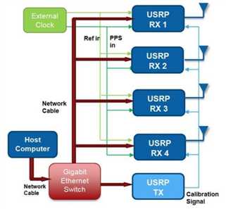
Figure 1 - Multi-Channel USRP-Based System for Direction Finding (note the calibration signal)
Other Variables That Effect Phase Alignment
As mentioned, other components aside from local oscillators contribute to phase error. Filters, mixers, amplifiers and other components produce phase offsets that vary with time, temperature, mechanical conditions, etc. These types of errors can generally be calibrated out with intermittent, low-rate routines that detect the channel-to-channel phase with a calibration tone. These errors will not change with each PLL retune but may change with time and temperature variation. Thus, applications that require RF phase alignment may require periodic calibration.
如前文所述, 除了本振以外的其他组件也会导致相位错误: 滤波器, 混频器, 放大器等其他孕检也会产生相位偏移, 并且相位偏移随时间, 温度, 自身机械特性等条件变化. 这种类型的相位错误可以通过间歇性, 规律性的校准信号来校准相位偏移. 并且这种错误不会随着每个PLL的重新调谐而变化, 但是会随着时间和温度而变化. 因此需要RF相位同步的应用需要定期校准.
USRP B100 and E100 – Not Recommended for MIMO
Like the USRP N200/N210, the USRP B100 and E100/110 can be synchronized with an external reference and PPS source. However, this does not imply the USRP B100 and E100/E110 are MIMO capable. The flexible frequency clocking architecture used in these devices produces phase ambiguity in ADC/DAC sample clocks. Therefore, sample edges will not be aligned. Despite the sample edge misalignment, it is still possible to produce samples with relatively accurate time stamps. This is useful for time-difference-of-arrival or similar algorithms.
USRP B100 和 E100/110 虽然可以像N200/N210一样使用外部参考信号和PPS源来实现同步, 但是这并不意味着 B100和 E100/110具有MIMO能力. 在这些设备中使用灵活的时钟频率架构导致ADC/DAC采样时钟的相位模糊. 因此采样边沿并没有对齐. 尽管如此, 这些设备依然可能提供相对正确的采样时间戳. 这是由于采用时间差定位法或者类似的算法.
One exception to these statements is when you make use of a daughterboard containing more than one channel in a single slot. For example, LFRX/TX, BasicRX/TX, and TVRX2 can all be used to achieve MIMO capability with a USRP B100 or E100/110.
有一个例外是, 当母板一个插槽上的子板有多余一个通道时, 例如子板LFRX/TX, BasicRX/TX, and TVRX2都可以使用B100 or E100/110实现MIMO.
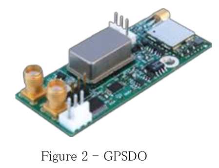
Synchronization with GPS Disciplined Oscillator
It is possible to provide time-synchronization over a wider geographic area with a GPS disciplined oscillator (GPSDO). A GPSDO derives 10 MHz/PPS signals from the GPS system. The GPSDO is accurate to approximately +/-50 ns across the globe. Ettus Research provides an optional GPSDO module with the USRP N200/N210. There is also an upgraded version of the OctoClock, which includes an internal GPSDO.
可以使用GPSDO在一个很大的地理区域内提供时间同步, 一个GPSDO生成的10MHz/PPS信号源于GPS系统, 精度大约+/- 50 ns. Ettus为USRP N200/N210提供可选的GPSDO模块, 同时也提供GPSDO的升级版OctoClock, 它包含一个内部的GPSDO.
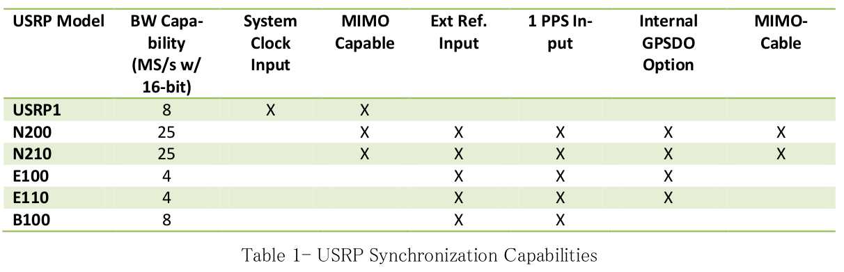
MIMO Capability of Ettus Research USRP Devices
Table 1 provides an overview of the synchronization and MIMO capabilities of the USRP product line.
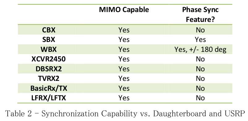
The RF daughterboard selection also impacts the synchronization experience. Most daughterboards use a fractional-N synthesizer to generate the local-oscillator signals. Generally, these fractional-N synthesizers introduce a random phase offset after each retune. If phase alignment between all RF channels is required, this random phase offset will need to be measured and compensated for in software. The SBX PLL includes a resync feature that resets to a fixed phase after each retune.
子板的选择同样会影响同步性能. 大多数子板采用N分频的频率合成器生成本振信号. 通常这些N分频频率合成器每一次重新调谐都会产生一个随机的相位偏移. 如果必须对齐所有通道的相位, 这个在软件中测量这个随机相位偏移并且对它进行补偿. SBX子板的PLL拥有一个再同步特性, 可以将每次重新调谐后的相位重置为一个固定的相位.
Thus, it may not need to be calibrated after each retune, but may require periodic calibration. This makes the SBX daughterboard the most ideal option for phased-array applications that fall within its frequency range. Also, the BasicRX/TX and LFRX/TX boards do not contain local oscillators that introduce phase errors.
因此可能不必每次重新调谐都校准, 但是需要定期校准. 这使得SBX子板在其频率范围内成为相控阵最理想的选择. BasicRX/TX 和 LFRX/TX子板也不含有引起相位错误的本振.
USRP N200/N210 – Plug and Play 2x2 MIMO System
The easiest method to implement a high-performance 2x2 MIMO system is to utilize two N200/N210s synchronized with an Ettus Research MIMO cable. In this configuration, a single Gigabit Ethernet(GigE) interface can be used to communicate with both USRP devices. The USRP connected to the GigE acts as a switch and routes data to/from both USRP devices. It will also handle time synchronization of the data so the sample alignment process is transparent to the user. The total sample rate for USRP devices connected to a single GigE port on the host computer cannot exceed 25 MS/s in 16-bit mode, or 50 MS/s in 8-bit mode.
实现一个2×2高性能MIMO系统, 最简单的方法是使用MIMO Cable连接两个N200/N210. 在这一配置下, 一个吉比特以太网接口可以用来与两台USRP设备通信. 连接网口的那台USRP设备充当两台设备的数据网关和路由. 并且会处理数据的时间同步, 因此对于用户来说, 样点对齐是显然的. 单网口连接模式(共享网络模式)下, 与主机通信的总速率在16-bit模式不能超过 25 MS/s, 或者8-bit模式不能超过50 MS/s.
Application Example – Visual Phase Alignment with N210 2X2 MIMO System
The UHD API allows you to select synchronization settings for each USRP device. These settings are also exposed through GNU Radio blocks. This allows for a quick, illustrative example of how to use the N200/N210 to build a MIMO system. GNU Radio Compnion (GRC) is used for this basic illustration.
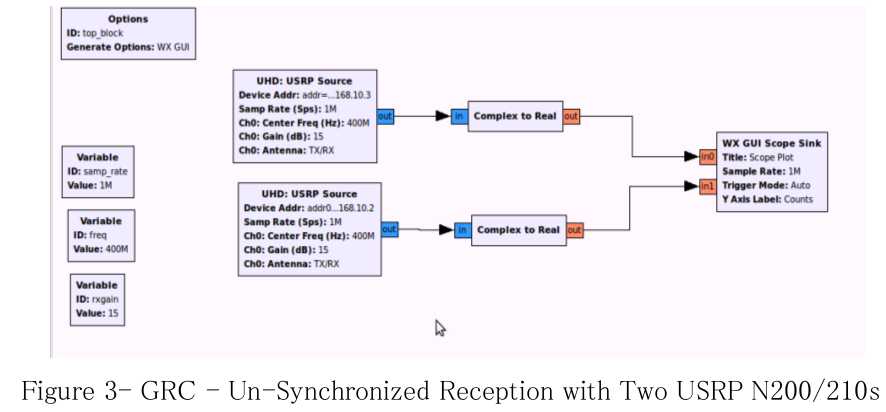
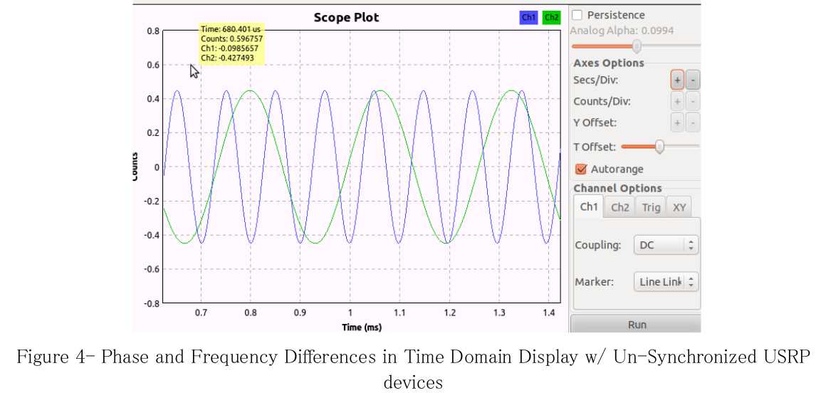
Figure 3 shows a flowgraph that receives two streams from two unsynchronized USRP devices. A 400.01 MHz tone is injected into both USRP devices, which are tuned to 400.00 MHz. The flow graph separates the real component of each complex baseband signal and plots them together on a WX GUI Scope. When the two USRP devices are synchronized, the scope sill show two, 10 kHz tones with constant relative phase. In this test case, the USRP devices are unsynchronized. Notice in Figure 4 that there are obvious phase and frequency differences between the two signals. This is a result of variations in the two unsynchronized reference clocks. Heat is applied to one of the USRP device’s internal reference crystals to amplify the frequency variation between the two units.
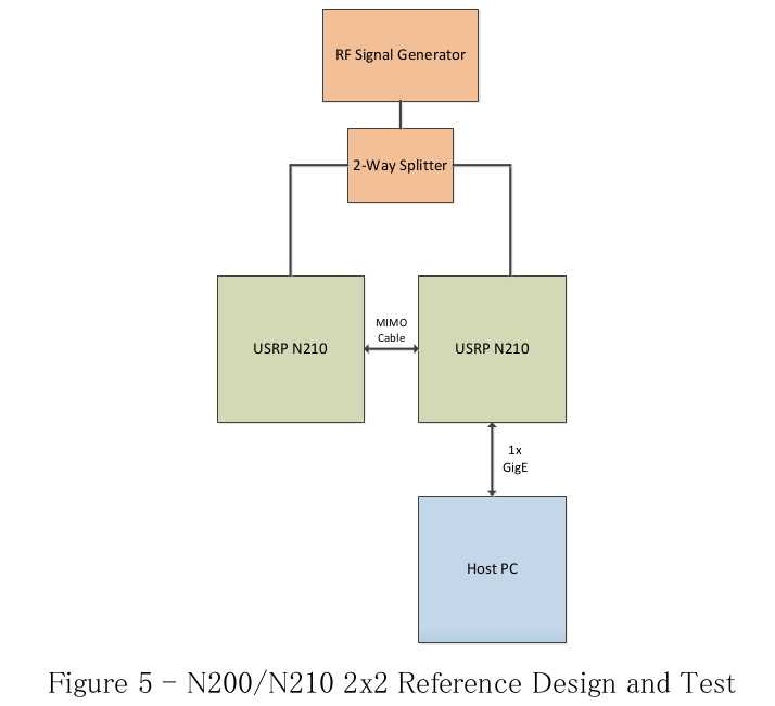
Next, plug-and-play 2X2 system is illustrated in Figure 5 . Notice the relative simplicity of the
system. A MIMO system is created by connecting two N200/N210s with a MIMO cable, which
shares Ethernet connectivity and common 10 MHz/PPS signals. Like the unsynchronized setup
that produce the scope view in Figure 4 , a signal generator drives the receiver inputs of both
inputs. A block diagram of the synchronized system is shown in Figure 5 . The flowgraph is shown
in Figure 6.
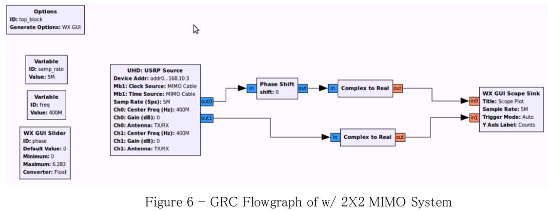
A single UHD block is used in the GRC flowgraph. The block parameters are configured to set up a
2x2 MIMO system. The settings of interest are:
Device addr: addr0=192.168.10.2,addr1=192.168.10.3
Sync = don‘t sync
Num Mboards = 2
Mb0 Clk Src = Default
Mb0 Time Src = Default
...
Mb1 Clk Src = MIMO Cable
Mb1 Time Src = MIMO CableThese settings configure the first USRP device, Mb0, which corresponds to the first entry in the
address string, to use its default reference for clocking and timing. The second USRP(Mb1) is
configured to accept its frequency and timing reference from the MIMO cable. The signals are
provided by Mb0. All other standard settings such as center frequency and gain assignments apply
as well.
Like the first flowgraph shown, the real part of each USRP stream is displayed on a scope. A phase
correction block is included to compensate for the random, but constant, phase offset discussed
earlier in this paper. Figure 7 includes a screenshot of the resultant display both before phase
adjustment. Note the phase is constant and the tones are the same frequency.
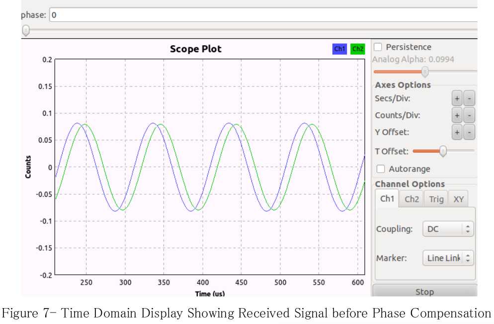
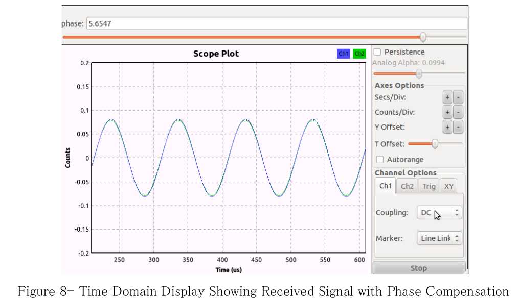
Figure 8 shows the signals with phase correction applied. In this plot, it is clear the MIMO
connection has enabled the frequency and time references to be synchronized. The random phase
offset is corrected with a complex phase shift in the flowgraph. In real applications, this phase
correction would be implicitly generated with algorithms such as maximum-ratio combining (MRC),
or periodic calibration.
This is a simple illustration of the MIMO capability provided by the USRP N200/N210. In most
applications the phase compensation is implemented with some automated process. However,
calibrating the devices with this type of manual correction is certainly an option.
All principles illustrated in this example are applicable to operations in the transmit direction.
Synchronization with 10 MHz and 1 PPS Signals
While the USRP N200 and N210 provide plug-and-play MIMO capability with the Ettus Research
MIMO cable, it is also possible to synchronize multiple devices using external 10 MHz and 1 PPS
distribution. This is useful if the developer would like to use a high-accuracy external reference
such as a Rubidium source. It is also helpful if the developer must build a MIMO system with more
than two channels.
If common PPS and 10 MHz signals are distributed to USRP N-Series devices, it is theoretically
possible to build arbitrarily large MIMO systems. In practice, developers have built systems with up
to 16 synchronized USRP devices.
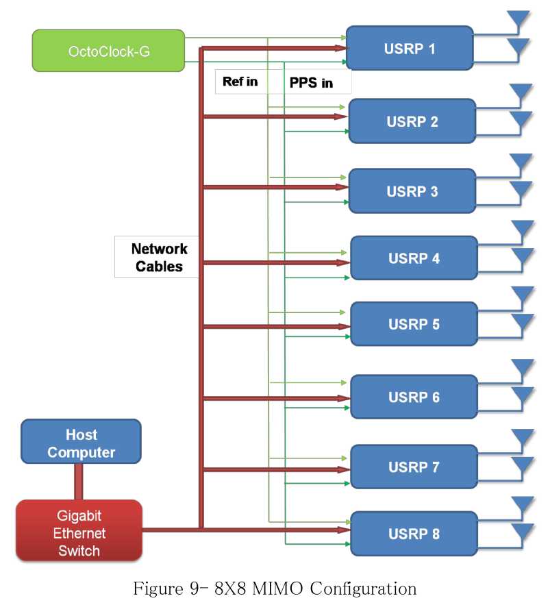
The Ettus Research OctoClock and OctoClock-G make it easy to distribute 10 MHz and 1 PPS
signals for multi-channel operation. The OctoClock serves as an 8-way PPS and 10 MHz reference
splitter. The user must provide a single 10 MHz and 1 PPS signal. The upgraded OctoClock-G
includes a high-accuracy, internal GPS-disciplined oscillator and does not require external signals
to be supplied. Figure 9 illustrates the use of an OctoClock-G to create an 8x8 MIMO system.
All timing signals from the OctoClock should be connected to the USRP devices with matched
length cable of the same type and connectorization. This ensures that there is low skew between all
of the channels.
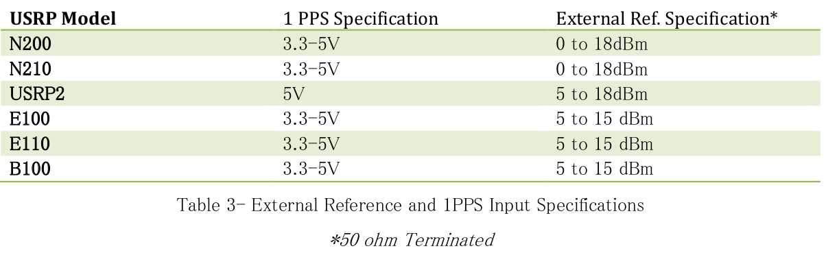
Synchronization Signals – Input Levels
To achieve optimum performance and prevent damage to the USRP devices, the designer must
assure that the input levels fall with specified limits. Guidance for input voltage levels and power
levels for the 1 PPS and 10 MHz inputs are shown in Table 3 .
Additional Resources
UHD API For Synchronization http://files.ettus.com/uhd_docs/manual/html/sync.html
OctoClock-G Product Page https://www.ettus.com/product/details/OctoClock-G
GPSDO Module for USRP N200/N210 https://www.ettus.com/product/details/GPSDO-KIT
以上是关于GNU Radio: Synchronization and MIMO Capability with USRP Devices的主要内容,如果未能解决你的问题,请参考以下文章