Unity URP Shader 实现几种视差映射
Posted
tags:
篇首语:本文由小常识网(cha138.com)小编为大家整理,主要介绍了Unity URP Shader 实现几种视差映射相关的知识,希望对你有一定的参考价值。
参考技术A float2 SteepParallaxMapping(TEXTURE2D_PARAM(heightMap, sampler_heightMap), half3 viewDirTS, half scale, float2 uv)//determine number of layers from angle between V and N
const float minLayers = 5;
const float maxLayers = 15;
float numLayers = lerp(minLayers, maxLayers, abs(dot(half3(0, 0, 1), viewDirTS)));
//height of each layer
float layerHeight = 1.0 / numLayers;
//depth of current layer
float currentLayerHeight = 0;
//shift of texture coordinates for each iteration
half2 dtex = scale * viewDirTS.xy / viewDirTS.z / numLayers;
//current texture coordinates
float2 currentTextureCoords = uv;
//get first depth from heightmap
float heightFromTexture = 1 - SAMPLE_TEXTURE2D(heightMap, sampler_heightMap, currentTextureCoords).g;
for(int i = 0; i < 15; i++)
if(heightFromTexture <= currentLayerHeight)
break;
//to the next layer
currentLayerHeight += layerHeight;
//shift texture coordinates along vector viewDirTS
currentTextureCoords -= dtex;
//get new depth from heightmap
heightFromTexture = 1 - SAMPLE_TEXTURE2D(heightMap, sampler_heightMap, currentTextureCoords).g;
return currentTextureCoords - uv;
float2 ReliefParallaxMapping(TEXTURE2D_PARAM(heightMap, sampler_heightMap), half3 viewDirTS, half scale, float2 uv)
// determine required number of layers
const float minLayers = 10;
const float maxLayers = 15;
float numLayers = lerp(minLayers, maxLayers, abs(dot(half3(0, 0, 1), viewDirTS)));
// height of each layer
float layerHeight = 1.0 / numLayers;
// depth of current layer
float currentLayerHeight = 0;
// shift of texture coordinates for each iteration
half2 dtex = scale * viewDirTS.xy / viewDirTS.z / numLayers;
// current texture coordinates
float2 currentTextureCoords = uv;
// depth from heightmap
float heightFromTexture = 1 - SAMPLE_TEXTURE2D(heightMap, sampler_heightMap, currentTextureCoords).g;
for(int i = 0; i < 15; i++)
if(heightFromTexture <= currentLayerHeight)
break;
// to the next layer
currentLayerHeight += layerHeight;
// shift texture coordinates along vector viewDirTS
currentTextureCoords -= dtex;
// get new depth from heightmap
heightFromTexture = 1 - SAMPLE_TEXTURE2D(heightMap, sampler_heightMap, currentTextureCoords).g;
///////////////////////////////////////////////////////////
// Start of Relief Parallax Mapping
// decrease shift and height of layer by half
half2 deltaTexCoord = dtex / 2;
float deltaHeight = layerHeight / 2;
// return to the mid point of previous layer
currentTextureCoords += deltaTexCoord;
currentLayerHeight -= deltaHeight;
// binary search to increase precision of Steep Paralax Mapping
const int numSearches = 5;
for(int j = 0; j < numSearches; j++)
// decrease shift and height of layer by half
deltaTexCoord /= 2;
deltaHeight /= 2;
// new depth from heightmap
heightFromTexture = 1 - SAMPLE_TEXTURE2D(heightMap, sampler_heightMap, currentTextureCoords).g;
// shift along or agains vector V
if(heightFromTexture > currentLayerHeight) // below the surface
currentTextureCoords -= deltaTexCoord;
currentLayerHeight += deltaHeight;
else // above the surface
currentTextureCoords += deltaTexCoord;
currentLayerHeight -= deltaHeight;
// return results
//parallaxHeight = currentLayerHeight;
return currentTextureCoords - uv;
float2 ParallaxOcclusionMapping(TEXTURE2D_PARAM(heightMap, sampler_heightMap), half3 viewDirTS, half scale, float2 uv)
// determine optimal number of layers
const float minLayers = 10;
const float maxLayers = 15;
float numLayers = lerp(minLayers, maxLayers, abs(dot(half3(0, 0, 1), viewDirTS)));
// height of each layer
float layerHeight = 1.0 / numLayers;
// current depth of the layer
float currentLayerHeight = 0;
// shift of texture coordinates for each layer
half2 dtex = scale * viewDirTS.xy / viewDirTS.z / numLayers;
// current texture coordinates
float2 currentTextureCoords = uv;
// depth from heightmap
float heightFromTexture = 1 - SAMPLE_TEXTURE2D(heightMap, sampler_heightMap, currentTextureCoords).g;
for(int i = 0; i < 15; i++)
if(heightFromTexture <= currentLayerHeight)
break;
// to the next layer
currentLayerHeight += layerHeight;
// shift texture coordinates along vector viewDirTS
currentTextureCoords -= dtex;
// get new depth from heightmap
heightFromTexture = 1 - SAMPLE_TEXTURE2D(heightMap, sampler_heightMap, currentTextureCoords).g;
/////////////////////////////////////////////////////////
// previous texture coordinates
half2 prevTCoords = currentTextureCoords + dtex;
// heights for linear interpolation
float nextH = heightFromTexture - currentLayerHeight;
float prevH = 1 - SAMPLE_TEXTURE2D(heightMap, sampler_heightMap, currentTextureCoords).g
- currentLayerHeight + layerHeight;
// proportions for linear interpolation
float weight = nextH / (nextH - prevH);
// interpolation of texture coordinates
float2 finalTexCoords = prevTCoords * weight + currentTextureCoords * (1.0-weight);
return finalTexCoords - uv;
//return currentTextureCoords - uv;
如果层数很多,那性能就会低。但如果层数少,就会有明显的锯齿现象产生,可以根据摄像机向量V和多边形法向N之间的夹角来动态的决定层的数量。
可以使用较少的层数进行一阶段陡峭视差检索
二阶段的二分查找算法仍然消耗性能,但相较陡峭视差映射可以得到更精确的结果
视差遮蔽映射可以使用相对较少的采样次数产生很好的结果。但视差遮蔽映射比浮雕视差映射更容易跳过高度图中的小细节,也更容易在高度图数据产生大幅度的变化时得到错误的结果。
视差映射技术的主要任务是修改纹理坐标,让平面看起来像是立体的。主要计算都是在Fragment Shader中进行。看看下面的图片。水平线0.0表示完全没有凹陷的深度,水平线1.0表示凹陷的最大深度。实际的几何体并没改变,其实一直都在0.0水平线上。图中的曲线代表了高度图中存储的高度数据。
设当前点(译者:原文中用的是Fragment,片元。)是图片中用黄色方块高亮出来的那个点,这个点的纹理坐标是T0。向量V是从摄像机到点的方向向量。用坐标T0在高度图上采样,你能得到这个点的高度值H(T0)=0.55。这个值不是0,所以点并不是在表面上,而是凹陷下去的。所以你得把向量V继续延长直到与高度图定义出来的表面最近的一个交点。这个交点我们说它的深度就是H(T1),它的纹理坐标就是T1。所以我们就应该用T1的纹理坐标去对颜色和法线贴图进行采样。
所以说,所有视差映射技术的主要目的,就是要精确的计算摄像机的向量V和高度图定义出来的表面的交点。
如图所示把表面的深度切分成等距的若干层。然后从最顶端的一层开始采样高度图,每一次会沿着V的方向偏移纹理坐标。如果点已经低于了表面(当前的层的深度大于采样出的深度),停止检查并且使用最后一次采样的纹理坐标作为结果。
陡峭视差映射的工作方式在下面的图片上举例。深度被分割成8个层,每层的高度值是0.125。每层的纹理坐标偏移是V.xy/V.z * scale/numLayers。从顶层黄色方块的位置开始检查。
以下参照下图给出算法的执行步骤:
层的深度为0,高度图深度H(T0)大约为0.75。采样到的深度大于层的深度,所以开始下一次迭代。
沿着V方向偏移纹理坐标,选定下一层。层深度为0.125,高度图深度H(T1)大约为0.625。采样到的深度大于层的深度,所以开始下一次迭代。
沿着V方向偏移纹理坐标,选定下一层。层深度为0.25,高度图深度H(T2)大约为0.4。采样到的深度大于层的深度,所以开始下一次迭代。
沿着V方向偏移纹理坐标,选定下一层。层深度为0.375,高度图深度H(T3)大约为0.2。采样到的深度小于层的深度,所以向量V上的当前点在表面之下。我们找到了纹理坐标Tp=T3是实际交点的近似点。
浮雕视差映射升级了陡峭视差映射。
算法一阶段采用陡峭视差映射得到交点前后的两个层,和对应的深度值。在下面的原理图中这两个层分别对应纹理坐标T2和T3。
算法在二阶段采用二分法来进一步改进你的结果,每一次搜索迭代可以使精确度提升一倍。
以下参照下图给出了算法的执行步骤:
在陡峭视差映射之后,我们知道交点肯定在T2和T3之间。真实的交点在图上用绿点标出来了。
设每次迭代时的纹理坐标变化量ST,它的初始值等于向量V在穿过一个层的深度时的XY分量。
设每次迭代时的深度值变化量SH,它的初始值等于一个层的深度。
把ST和SH都除以2。
把纹理坐标T3沿着反方向偏移ST,把层深度沿反方向偏移SH,得到此次迭代的纹理坐标T4和层深度H(T4)。
(*)采样高度图,把ST和SH都除以2。
如果高度图中的深度值大于当前迭代层的深度H(T4),则将当前迭代层的深度增加SH,迭代的纹理坐标沿着V的方向增加ST。
如果高度图中的深度值小于当前迭代层的深度H(T4),则将当前迭代层的深度减少SH,迭代的纹理坐标沿着V的相反方向增加ST。
从(*)处循环,继续二分搜索,直到规定的次数。
最后一步得到的纹理坐标就是浮雕视差映射取到的近似结果。
视差遮蔽映射(POM)是陡峭视差映射的另一个改进版本。
算法一阶段采用陡峭视差映射得到交点前后的两个层,和对应的深度值。在下面的原理图中这两个层分别对应纹理坐标T2和T3。
算法二阶段对一阶段获得的两个纹理偏移值进行插值。如原理图所示,POM使用相交之后的层深度(0.375,陡峭视差映射停止迭代的层),上一个采样深度H(T2)和下一个采样深度H(T3)。从图片中你能看到,视差遮蔽映射的插值结果是在视向量V和H(T2)和H(T3)高度的连线的交点上。这个交点已经足够接近实际交点(标记为绿色的点)了。
[译] GLSL 中的视差遮蔽映射(Parallax Occlusion Mapping in GLSL)
Unity商业Shader渲染-URP-基于AmplifyShader Editor
LWRP/URP/HDRP区别
URP其实也叫LWRP,也是URP的前身
如果一直以来有使用Unity的同学可能知道
在2019年初的时候,一开始Unity预备区分低清和高清渲染,当然现在也这样,所谓低清就是:light weight render pipline(简称:LWRP)这个包负责
时至今日,LWRP的项目已经不多(当年很多有实力的示例项目),完全转成URP也不是难事
所以,完全不同担心URP和LWRP的差异导致生产环境的问题,或影响(社区因为人多,当中也很多解决方案)
URP和原PIPLINE的区别
其他可以看看官网图,下面是官网的对比表链接和图。
https://docs.unity3d.com/Packages/com.unity.render-pipelines.universal@8.2/manual/universalrp-builtin-feature-comparison.html

URP实际应用限制还很多
真无两头利,你要马跑的快,还要马不吃草,这是不可能的
如果说URP比原渲染管线轻量,那么URP肯定限制多得多得多
理论就不说了,直接说实际应用
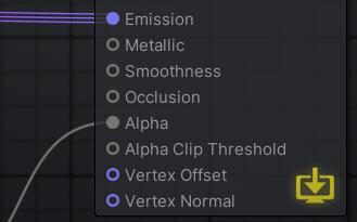
透明通道没了
(也可能是我用的Amplify的原因)
一开始发现明明有Alpha参数啊,就是不生效

最后发现:这段代码,所以解决方法:要开Alphtest
				#ifdef _ALPHATEST_ON
					clip(Alpha - AlphaClipThreshold);
				#endif
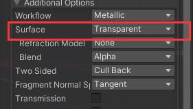
* *改变shader的属性(有点用,但不是那回事,不是真正的解决方法)
* 在某论坛,找到了方法,添加custom节点

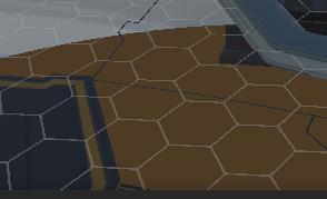
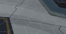
解决后对比


一般的后处理,bloom等不能用了
(有点急今天,之后再补充)
参考:
有官方的URP和built-in URP的详细对比(官方文档)
也有Amplify论坛,社区的讨论
Amplify Shader在国内不流行就是了(应该用作生产的团队不多,不然,为什么国内讨论的少,我的文章居然目前是唯一作技术讨论的)
Unity URP/SRP 渲染管线浅入深出【匠】_以笑对世~的博客-CSDN博客_unity urp
Unity URP渲染管线---自定义渲染详解(入门)_HumorChess的博客-CSDN博客_urp渲染管线
Unity - 通用渲染管线(URP)1.渲染、后处理_祝你万事顺利的博客-CSDN博客_unity urp
游戏开发中的坑之三 通过ASE(Amplify Shader Editor)创建Shader [持续更新.....]_yijiankun100的开发日记-CSDN博客_ase unityUnity通用渲染管线(URP)系列(一)——自定义渲染管线 - 知乎 (zhihu.com)fffUnity图形渲染Part4/4——通用渲染管线(URP)教程系列(持续更新) - 知乎 (zhihu.com)
最后的链接还有版权声明参照案例,可以,赞
国外大神对amiplify shader template以及节点的二次开发:
以上是关于Unity URP Shader 实现几种视差映射的主要内容,如果未能解决你的问题,请参考以下文章
