BetaFlight深入传感设计之二:Mag传感模块
Posted lida2003
tags:
篇首语:本文由小常识网(cha138.com)小编为大家整理,主要介绍了BetaFlight深入传感设计之二:Mag传感模块相关的知识,希望对你有一定的参考价值。
BetaFlight深入传感设计之二:Mag传感模块
- 1. HwPreInit/HwInit阶段
- 2. HwIo阶段
- 3. HwDataAnalysis阶段
- 4. 总结
- 5. 参考资料
Mag地磁传感器主要根据地球磁场以及电磁学物理特性来判断当前传感器指向。
根据BetaFlight深入传感设计:传感模块设计框架,我们针对如下几个阶段进行分析。
1. HwPreInit/HwInit阶段
1.1 【业务HwPreInit】compassPreInit
该阶段对SPI片选信号脚进行了硬件配置(仅当代码宏定义支持SPI的情况下)。
compassPreInit
 └──> <USE_SPI><compassConfig()->mag_busType == BUS_TYPE_SPI>
     └──> spiPreinitRegister(compassConfig()->mag_spi_csn, IOCFG_IPU, 1)
1.2 【业务HwInit】compassInit
业务初始化阶段主要涉及:
- compassDetect //硬件芯片检测
- magDev.init //设备总线初始化
- buildRotationMatrixFromAlignment //传感方向对齐
compassInit
 ├──> <!compassDetect(&magDev, &alignment)>
 │   └──> return false
 ├──> [initialize and calibration. turn on led during mag calibration (calibration routine blinks it)]
 ├──> magDev.init(&magDev)
 ├──> <compassConfig()->mag_alignment != ALIGN_DEFAULT>
 │   └──> magDev.magAlignment = compassConfig()->mag_alignment
 ├──> buildRotationMatrixFromAlignment(&compassConfig()->mag_customAlignment, &magDev.rotationMatrix)
 └──> return true
注:对于地磁传感器来说,通过闭合导体切割磁力线形成感应电流,从而导致电位差,进而被ADC采集。通过三维空间判断磁场矢量,判断地磁角方向。
1.2.1 compassDetect
目前,支持以下硬件规格磁力计传感器:
- MAG_HMC5883
- MAG_AK8975
- MAG_AK8963
- MAG_QMC5883
- MAG_LIS3MDL
- MAG_MPU925X_AK8963
根据BetaFlight深入传感设计:传感模块设计框架,下面以HMC5883为例:
- hmc5883lInit
- hmc5883lRead
hmc5883lDetect
 ├──> extDevice_t *dev = &mag->dev
 ├──> <USE_MAG_SPI_HMC5883><dev->bus->busType == BUS_TYPE_SPI>
 │   └──> hmc5883SpiInit(dev)
 ├──> <USE_MAG_HMC5883><dev->bus->busType == BUS_TYPE_I2C && dev->busType_u.i2c.address == 0>
 │   └──> dev->busType_u.i2c.address = HMC5883_MAG_I2C_ADDRESS
 ├──> bool ack = busReadRegisterBuffer(&mag->dev, HMC58X3_REG_IDA, &sig, 1)
 ├──> <!ack || sig != HMC5883_DEVICE_ID>
 │   └──> return false
 ├──> mag->init = hmc5883lInit
 ├──> mag->read = hmc5883lRead
 └──> return true


#define HMC5883_MAG_I2C_ADDRESS     0x1E
#define HMC5883_DEVICE_ID           0x48
注:默认的HMC5883 mag芯片I2C地址 0x1E。
1.2.2 buildRotationMatrixFromAlignment
根据传感器&飞控板方向对齐页面 或者 cli配置参数,建立旋转矩阵,将芯片检测到的磁场方向旋转到与飞机一致的方向。
或者 从cli获取相关mag_align参数。
# get mag
align_mag = CUSTOM
Allowed values: DEFAULT, CW0, CW90, CW180, CW270, CW0FLIP, CW90FLIP, CW180FLIP, CW270FLIP, CUSTOM
Default value: DEFAULTmag_align_roll = 0
Allowed range: -3600 - 3600mag_align_pitch = 1800
Allowed range: -3600 - 3600
Default value: 0mag_align_yaw = 1350
Allowed range: -3600 - 3600
Default value: 0
该方向在代码中,通过配置参数对Mag对象的旋转矩阵进行初始化完成。
void buildRotationMatrixFromAlignment(const sensorAlignment_t* sensorAlignment, fp_rotationMatrix_t* rm)
 ├──> rotationAngles.angles.roll  = DECIDEGREES_TO_RADIANS(sensorAlignment->roll)
 ├──> rotationAngles.angles.pitch = DECIDEGREES_TO_RADIANS(sensorAlignment->pitch)
 ├──> rotationAngles.angles.yaw   = DECIDEGREES_TO_RADIANS(sensorAlignment->yaw)
 └──> buildRotationMatrix(&rotationAngles, rm)

void buildRotationMatrix(fp_angles_t *delta, fp_rotationMatrix_t *rotation)

    float cosx, sinx, cosy, siny, cosz, sinz
    float coszcosx, sinzcosx, coszsinx, sinzsinx

    cosx = cos_approx(delta->angles.roll)
    sinx = sin_approx(delta->angles.roll)
    cosy = cos_approx(delta->angles.pitch)
    siny = sin_approx(delta->angles.pitch)
    cosz = cos_approx(delta->angles.yaw)
    sinz = sin_approx(delta->angles.yaw)

    coszcosx = cosz * cosx
    sinzcosx = sinz * cosx
    coszsinx = sinx * cosz
    sinzsinx = sinx * sinz

    rotation->m[0][X] = cosz * cosy
    rotation->m[0][Y] = -cosy * sinz
    rotation->m[0][Z] = siny
    rotation->m[1][X] = sinzcosx + (coszsinx * siny)
    rotation->m[1][Y] = coszcosx - (sinzsinx * siny)
    rotation->m[1][Z] = -sinx * cosy
    rotation->m[2][X] = (sinzsinx) - (coszcosx * siny)
    rotation->m[2][Y] = (coszsinx) + (sinzcosx * siny)
    rotation->m[2][Z] = cosy * cosx


typedef union sensorAlignment_u
    // value order is the same as axis_e

    // values are in DECIDEGREES, and should be limited to +/- 3600

    int16_t raw[XYZ_AXIS_COUNT]
    struct
        int16_t roll
        int16_t pitch
        int16_t yaw

 sensorAlignment_t

#define SENSOR_ALIGNMENT(ROLL, PITCH, YAW) ((sensorAlignment_t)\\
    .roll = DEGREES_TO_DECIDEGREES(ROLL), \\
    .pitch = DEGREES_TO_DECIDEGREES(PITCH), \\
    .yaw = DEGREES_TO_DECIDEGREES(YAW), \\
)
注:根据配置建立旋转矩阵,详见上面buildRotationMatrix函数。
1.2.3 hmc5883lInit
hmc5883lInit
 ├──> [leave test mode]
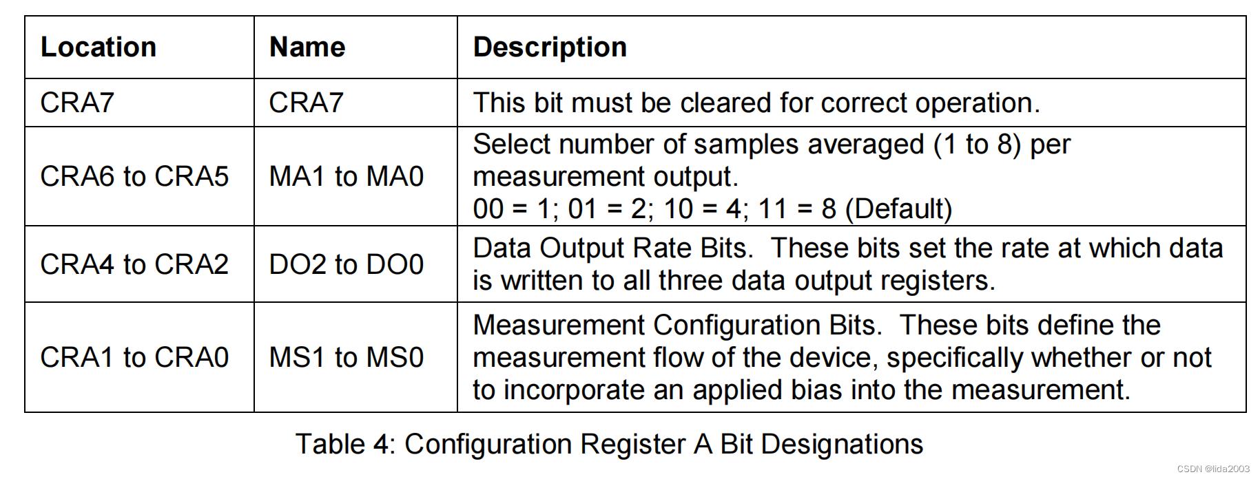
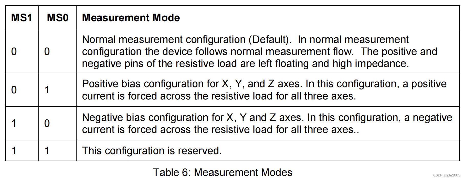
 │   ├──> busWriteRegister(dev, HMC58X3_REG_CONFA, HMC_CONFA_8_SAMLES | HMC_CONFA_DOR_15HZ | HMC_CONFA_NORMAL)    // Configuration Register A  -- 0 11 100 00  num samples: 8  output rate: 15Hz  normal measurement mode
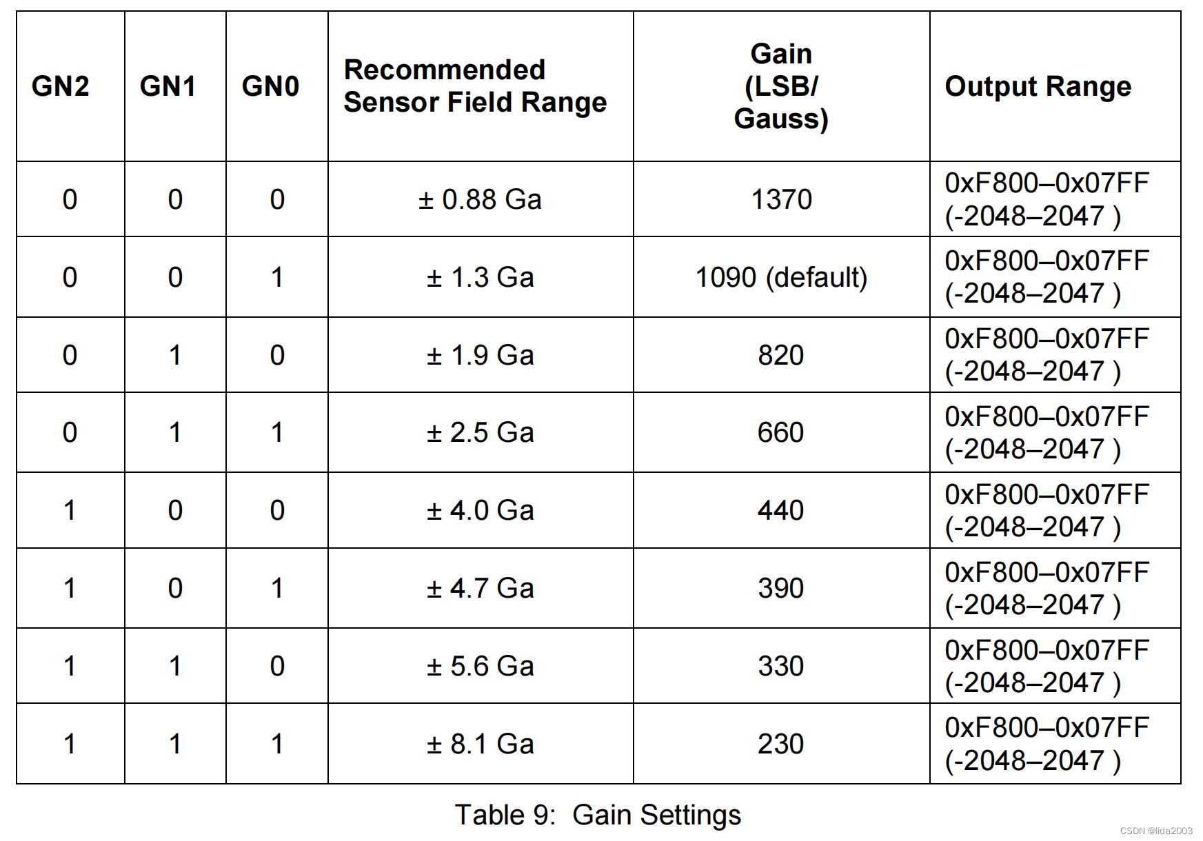
 │   ├──> busWriteRegister(dev, HMC58X3_REG_CONFB, HMC_CONFB_GAIN_1_3GA)                                          // Configuration Register B  -- 001 00000    configuration gain 1.3Ga
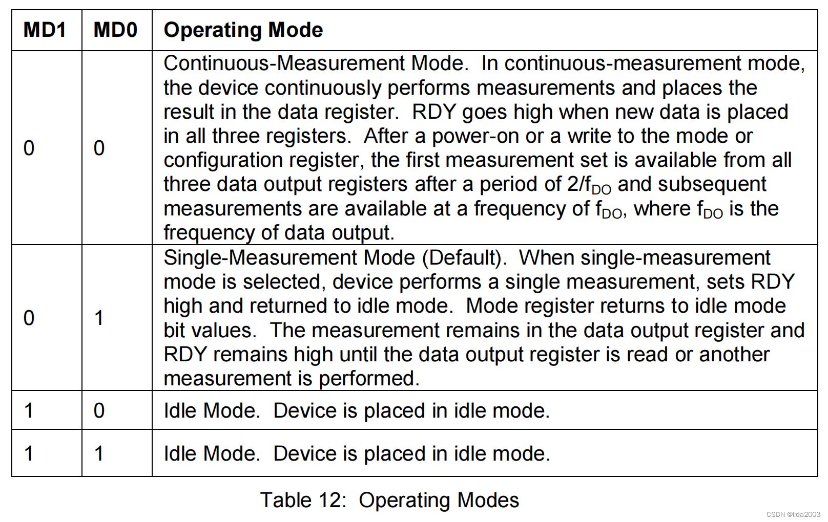
 │   └──> busWriteRegister(dev, HMC58X3_REG_MODE, HMC_MODE_CONTINOUS)                                             // Mode register             -- 000000 00    continuous Conversion Mode
 ├──> delay(100)
 ├──>  hmc5883lConfigureDataReadyInterruptHandling(mag)
 └──> return true

#define HMC58X3_REG_CONFA           0x00
#define HMC58X3_REG_CONFB           0x01
#define HMC58X3_REG_MODE            0x02

#define HMC_CONFA_NORMAL            0x00
#define HMC_CONFA_DOR_15HZ          0X10
#define HMC_CONFA_8_SAMLES          0X60
#define HMC_CONFB_GAIN_1_3GA        0X20
#define HMC_MODE_CONTINOUS          0X00
注:关于寄存机的详细内容,请查阅:HMC5883L datasheet。
1.2.3.1 Configuration Register A
1.2.3.2 Configuration Register B
1.2.3.3 Mode Register
1.2.4 hmc5883lRead
hmc5883lRead
 ├──> static uint8_t buf[6]
 ├──> static bool pendingRead = true
 ├──> <pendingRead>
 │   ├──> busReadRegisterBufferStart(dev, HMC58X3_REG_DATA, buf, sizeof(buf))
 │   ├──> pendingRead = false
 │   └──> return false
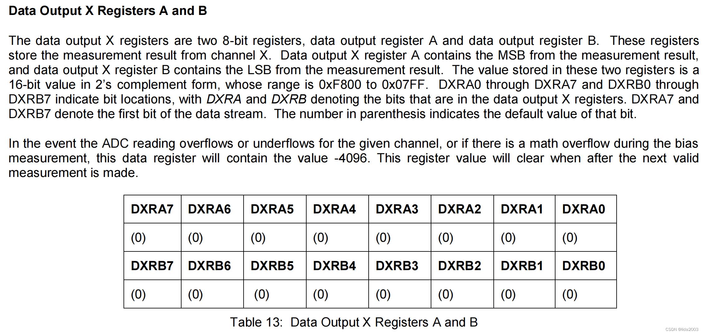
 ├──> magData[X] = (int16_t)(buf[0] << 8 | buf[1])
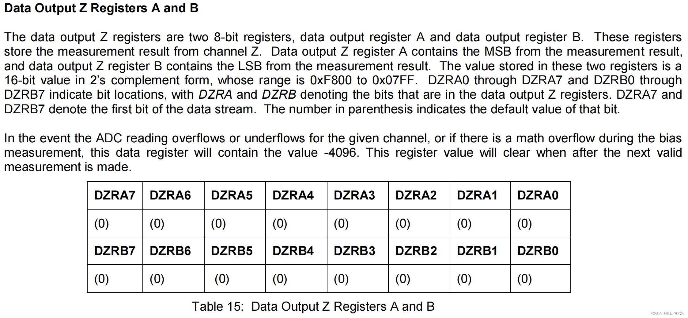
 ├──> magData[Z] = (int16_t)(buf[2] << 8 | buf[3])
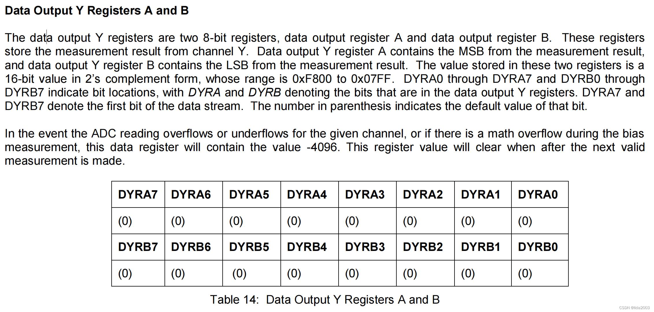
 ├──> magData[Y] = (int16_t)(buf[4] << 8 | buf[5])
 ├──> pendingRead = true
 └──> return true

#define HMC58X3_REG_DATA            0x03
1.2.4.1 Data Output X Register A and B
1.2.4.2 Data Output Y Register A and B
1.2.4.3 Data Output Z Register A and B
2. HwIo阶段
该阶段主要确保数据采集及原始数据的有效性,其决策函数提供了判断原始数据有效性的方法。
获取到的数据mag.magADC[N], N= X,Y,Z,经过以下处理:
- 去除校准offset
- 传感值旋转对齐
【决策】compassIsHealthy/compassIsHealthy

taskUpdateMag
 └──> 【业务】compassUpdate
     ├──> hmc5883lRead
     └──> alignSensorViaMatrix/alignSensorViaRotation
3. HwDataAnalysis阶段
数据分析阶段主要是将传感器采集得到的原始数据进一步分析,并配合业务提供相关支持。
3.1 Calibration
在地球磁场环境下,校准地磁计:获取最大最小值,从而得到中间值。
注:建议飞行环境变化时,根据当地情况校准一次磁力计,该传感器受地磁和周边干扰影响较大。
【决策】compassIsCalibrationComplete

processRcStickPositions  // 遥控器操作校准: THR_HI + YAW_HI + PIT_LO + ROL_CE
 └──> 【业务】compassStartCalibration

mspProcessInCommand  // 地面配置站触发校准
 └──> 【业务】compassStartCalibration
3.2 Mag Caclulation
这里主要根据Mahony算法来计算方向,提供误差值供后续程序做方向的PI修正。
注:关于Mahony算法暂时还不太明白,后续看了再来和大家讨论。
imuUpdateAttitude
 └──> imuCalculateEstimatedAttitude
     └──> imuMahonyAHRSupdate
注:相关更新任务,详见:BetaFlight模块设计之二十七:姿态更新任务分析。
对于磁力计数据,我们假设磁场垂直于重力,因此忽略地球磁场中的Z分量,并且磁场方向不涉及飞机roll/pitch控制,主要是yaw的方向。
imuMahonyAHRSupdate
 ├──> ...
 ├──> <USE_MAG>
 │   ├──> [Use measured magnetic field vector]
 │   │   ├──> float mx = mag.magADC[X];
 │   │   ├──> float my = mag.magADC[Y];
 │   │   └──> float mz = mag.magADC[Z];
 │   ├──> float recipMagNorm = sq(mx) + sq(my) + sq(mz);
 │   └──> <useMag && recipMagNorm > 0.01f>
 │       ├──> [Normalise magnetometer measurement]
 │       │   ├──> recipMagNorm = invSqrt(recipMagNorm);
 │       │   ├──> mx *= recipMagNorm;
 │       │   ├──> my *= recipMagNorm;
 │       │   └──> mz *= recipMagNorm;
 │       ├──> const float hx = rMat[0][0] * mx + rMat[0][1] * my + rMat[0][2] * mz; // (hx; hy; 0) - measured mag field vector in EF (assuming Z-component is zero)
 │       ├──> const float hy = rMat[1][0] * mx + rMat[1][1] * my + rMat[1][2] * mz; // (hx; hy; 0) - measured mag field vector in EF (assuming Z-component is zero)
 │       ├──> const float bx = sqrtf(hx * hx + hy * hy); // (bx; 0; 0) - reference mag field vector heading due North in EF (assuming Z-component is zero)
 │       ├──> const float ez_ef = -(hy * bx); // magnetometer error is cross product between estimated magnetic north and measured magnetic north (calculated in EF)
 │       └──> [Rotate mag error vector back to BF and accumulate]
 │           ├──> ex += rMat[2][0] * ez_ef;
 │           ├──> ey += rMat[2][1] * ez_ef;
 │           └──> ez += rMat[2][2] * ez_ef;
 └──> ...
4. 总结
磁力计传感器的数据采集和有效数据清理方面并不复杂,只是在后续飞控在四元组和矢量旋转,以及Mahony算法方面,确实不是一下子能够搞明白的。至少我花了3-4个小时,目前没有搞明白。等有时间熟悉了,在和大家唠嗑吧!!!!
5. 参考资料
【1】BetaFlight深入传感设计:传感模块设计框架
【2】BetaFlight模块设计之十:磁力计任务分析
【3】BetaFlight模块设计之二十七:姿态更新任务分析
以上是关于BetaFlight深入传感设计之二:Mag传感模块的主要内容,如果未能解决你的问题,请参考以下文章


