Cordic基于FPGA的Cordic算法实现
Posted fpga和matlab
tags:
篇首语:本文由小常识网(cha138.com)小编为大家整理,主要介绍了Cordic基于FPGA的Cordic算法实现相关的知识,希望对你有一定的参考价值。
1.软件版本
Quartusii12.1
2.本算法理论知识
ROM资源,作为产生离散正弦信号的另一种有效途径,CORDIC(坐标旋转数值计算)算法已越来越受到青睐。其基本思想是通过一系列逐次递减的、与运算基数相关的往复偏摆以逼近最终需要达到的旋转角度。该算法仅利用加法和移位两种运算通过迭代方式进行矢量旋转, CORDIC算法由于只采用加法和移位运算,因此很适合在FPGA中实现,它可以用来实现数字下变频中的NCO、混频器和坐标变换等功能。
实现NCO的另一种方法是采用基于坐标旋转数字式计算机的算法,即CORDIC算法,基本思想是采用逐次逼近的方法实现三角函数的计算。该算法的突出优点是,仅做加减和移位运算,结合流水线,可以实现每一个时钟周期输出一个经过n次迭代的结果。

通过迭代的方式,可以用如下的式子可以知道其表达式为:
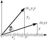 :
:


这里假设每次迭代所产生的小角度旋转的方向,引入一个变量表示每次迭代的剩余角度:
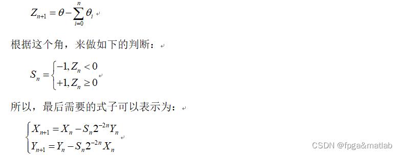
下面在FPGA下实现该算法。
3.部分源码
module cordic_top(
                 i_clk,
                 i_reset,
                 i_phase_in,
                 o_sin_out,
                 o_cos_out
                 );


input      i_clk;       //?????
input      i_reset;     //???????
input [7:0]i_phase_in;  //??????????
output[7:0]o_sin_out;   //??
output[7:0]o_cos_out;   //??


reg[7:0]reg_phase = 8'd0;

reg[7:0]o_sin_out = 8'd0;
reg[7:0]o_cos_out = 8'd0;

reg[7:0]x0 = 8'd0;
reg[7:0]y0 = 8'd0;
reg[7:0]z0 = 8'd0;

reg[7:0]x1 = 8'd0;
reg[7:0]y1 = 8'd0;
reg[7:0]z1 = 8'd0;

reg[7:0]x2 = 8'd0;
reg[7:0]y2 = 8'd0;
reg[7:0]z2 = 8'd0;

reg[7:0]x3 = 8'd0;
reg[7:0]y3 = 8'd0;
reg[7:0]z3 = 8'd0;

reg[7:0]x4 = 8'd0;
reg[7:0]y4 = 8'd0;
reg[7:0]z4 = 8'd0;

reg[7:0]x5 = 8'd0;
reg[7:0]y5 = 8'd0;
reg[7:0]z5 = 8'd0;

reg[7:0]x6 = 8'd0;
reg[7:0]y6 = 8'd0;
reg[7:0]z6 = 8'd0;

reg[7:0]x7 = 8'd0;
reg[7:0]y7 = 8'd0;
reg[7:0]z7 = 8'd0;

integer i;
reg[1:0]quadrant[8:0];


always @(posedge i_clk or posedge i_reset)
begin
     if(i_reset)
     begin
     reg_phase <= 8'h00;
     end
else begin
        case(i_phase_in[7:8-2])
        2'b00:  reg_phase <= i_phase_in;
        2'b01:  reg_phase <= i_phase_in - 8'h40;  //-pi/2
        2'b10:  reg_phase <= i_phase_in - 8'h80;  //-pi
        2'b11:  reg_phase <= i_phase_in - 8'hc0;  //-3pi/2
        default:reg_phase <= 8'h00;
        endcase
     end
end

always @(posedge i_clk or posedge i_reset)
begin
     if(i_reset)
     begin
     x0 <= 8'h00;
     y0 <= 8'h00;
     z0 <= 8'h00;
     end
else begin
     x0 <= 8'h4d;
     y0 <= 8'h00;
     z0 <= reg_phase;
     end
end

//?????1?
always @(posedge i_clk or posedge i_reset)
begin
     if(i_reset)
     begin
         x1<=8'b0000_0000;
         y1<=8'b0000_0000;
         z1<=8'b0000_0000;
     end
else begin
          if(z0[7]==1'b0)
          begin
          x1 <= x0 - y0;
          y1 <= y0 + x0;
          z1 <= z0 - 8'h20;  //45deg
          end
     else begin
          x1 <= x0 + y0;
          y1 <= y0 - x0;
          z1 <= z0 + 8'h20;  //45deg
          end
     end
end

//?????2?
always @(posedge i_clk or posedge i_reset)
begin
     if(i_reset)
     begin
         x2<=8'b0000_0000;
         y2<=8'b0000_0000;
         z2<=8'b0000_0000;
     end
else begin
          if(z1[7]==1'b0)
          begin
          x2 <= x1 - y1[7],y1[7:1];
          y2 <= y1 + x1[7],x1[7:1];
          z2 <= z1 - 8'h12;  //26deg
          end
     else begin
          x2 <= x1 + y1[7],y1[7:1];
          y2 <= y1 - x1[7],x1[7:1];
          z2 <= z1 + 8'h12;  //26deg
          end
     end
end

//?????3?
always @(posedge i_clk or posedge i_reset)
begin
     if(i_reset)
     begin
         x3<=8'b0000_0000;
         y3<=8'b0000_0000;
         z3<=8'b0000_0000;
     end
else begin
          if(z2[7]==1'b0)
          begin
          x3 <= x2 - 2y2[7],y2[7:2];
          y3 <= y2 + 2x2[7],x2[7:2];
          z3 <= z2 - 8'h09;  //14deg
          end
     else begin
          x3 <= x2 + 2y2[7],y2[7:2];
          y3 <= y2 - 2x2[7],x2[7:2];
          z3 <= z2 + 8'h09;  //14deg
          end
     end
end

//?????4?
always @(posedge i_clk or posedge i_reset)
begin
     if(i_reset)
     begin
     x4<=8'b0000_0000;
     y4<=8'b0000_0000;
     z4<=8'b0000_0000;
     end
else begin
          if(z3[7]==1'b0)
          begin
          x4 <= x3 - 3y3[7],y3[7:3];
          y4 <= y3 + 3x3[7],x3[7:3];
          z4 <= z3 - 8'h04;  //7deg
          end
     else begin
          x4 <= x3 + 3y3[7],y3[7:3];
          y4 <= y3 - 3x3[7],x3[7:3];
          z4 <= z3 + 8'h04;  //7deg
          end
     end
end

//?????5?
always @(posedge i_clk or posedge i_reset)
begin
     if(i_reset)
     begin
         x5<=8'b0000_0000;
         y5<=8'b0000_0000;
         z5<=8'b0000_0000;
     end
else begin
          if(z4[7]==1'b0)
          begin
          x5 <= x4 - 4y4[7],y4[7:4];
          y5 <= y4 + 4x4[7],x4[7:4];
          z5 <= z4 - 8'h02;  //4deg
          end
     else begin
          x5 <= x4 + 4y4[7],y4[7:4];
          y5 <= y4 - 4x4[7],x4[7:4];
          z5 <= z4 + 8'h02;  //4deg
          end
     end
end

//?????6?
always @(posedge i_clk or posedge i_reset)
begin
     if(i_reset)
     begin
         x6<=8'b0000_0000;
         y6<=8'b0000_0000;
         z6<=8'b0000_0000;
     end
else begin
          if(z5[7]==1'b0)
          begin
          x6 <= x5 - 5y5[7],y5[7:5];
          y6 <= y5 + 5x5[7],x5[7:5];
          z6 <= z5 - 8'h01;  //2deg
          end
     else begin
          x6 <= x5 + 5y5[7],y5[7:5];
          y6 <= y5 - 5x5[7],x5[7:5];
          z6 <= z5 + 8'h01;  //2deg
          end
     end
end


always @(posedge i_clk or posedge i_reset)
begin
     if(i_reset)
     begin
         for(i=0; i<=8; i=i+1)
         begin
         quadrant[i]<=2'b00;
         end
     end
else begin
         for(i=0; i<8; i=i+1)
         begin
         quadrant[i+1] <= quadrant[i];
         quadrant[0]   <= i_phase_in[7:6];
         end
     end
end

always @(posedge i_clk or posedge i_reset)
begin
      if(i_reset)
      begin
      o_sin_out <= 8'b0000_0000;
      o_cos_out <= 8'b0000_0000;
      end
else begin
         case(quadrant[7])
            2'b00:begin
                  o_sin_out <= y6;
                  o_cos_out <= x6;
                  end
            2'b01:begin
                  o_sin_out <= x6;
                  o_cos_out <= ~(y6) + 1'b1;
                  end
            2'b10:begin
                  o_sin_out <= ~(y6) + 1'b1;
                  o_cos_out <= ~(x6) + 1'b1;
                  end
            2'b11:begin
                  o_sin_out <= ~(x6) + 1'b1;
                  o_cos_out <= y6;
                  end
         default:begin
                 o_sin_out <= 8'b0000_0000;
                 o_cos_out <= 8'b0000_0000;
                 end
         endcase
      end
end

endmodule
4.仿真分析
在FPGA中进行设计,其主要硬件资源占用如下所示:
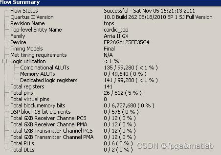
从上面的仿真结果可以看到,使用cordic算法,基本不占用FPGA内部的BRAM资源。在硬件资源上大大节约了。
其仿真结果如下所示:
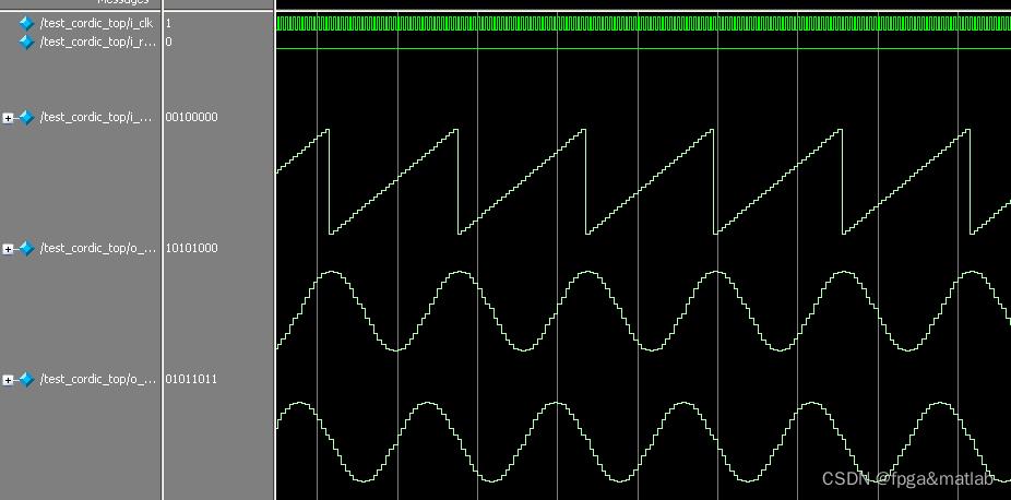
其RTL级的电路图如下所示:
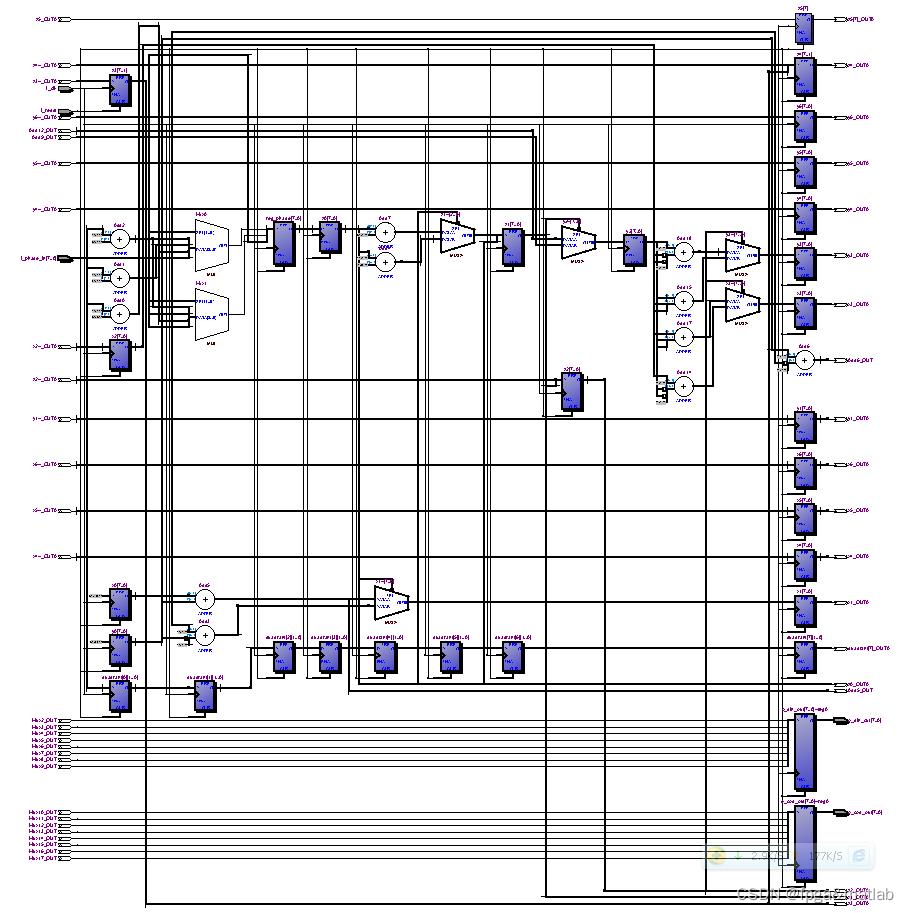
从上面的仿真介绍可知,基于查找表的NCO,这种方式的固有特点决定了不仅需要大量的FPGA资源,而且混频器在实现过程中需要占用一定的乘法器资源,这对乘法器资源有限的FPGA而言很不利。
基于CORDIC算法的NCO,通过一系列固定的与运算基数相关的角度不断偏摆来逼近所需的旋转角度,其硬件结构简单,易于并行化处理。A01-115
以上是关于Cordic基于FPGA的Cordic算法实现的主要内容,如果未能解决你的问题,请参考以下文章