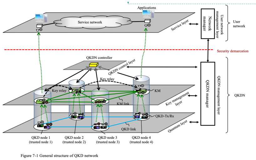
General structure of QKDN
Posted limer98
tags:
篇首语:本文由小常识网(cha138.com)小编为大家整理,主要介绍了General structure of QKDN相关的知识,希望对你有一定的参考价值。
源自:ITU-T Y.QKDN Arch文稿
1. General structure of QKDN
Figure 1 summarizes the reference model and main elements of a QKDN and a user network based in [ITU-T Y.3800]. A QKDN consists of QKD links, KM links, and QKD nodes (trusted nodes) in each of which QKD device/devices (a transmitter (QKD-Tx) and a receiver (QKD-Rx)) and a KM are located. Pairs of QKD devices connected by a point-to-point QKD link constitute the quantum layer. Each pair generates keys in its own way. Generated keys are pushed up to KMs and relayed via KM links. KMs and KM links constitutes the key management layer, which realizes the interconnectivity of key distribution between any designated nodes in a QKD network. The elements in these layers are controlled by the QKDN controller in the QKDN control layer. The whole of QKDN is managed by the QKDN manager in the QKDN management layer. Keys are supplied from the KM to cryptographic applications in a user network (specifically in the service layer).
Typical operation scenario is as follows. cryptographic applications in the service layer inform the KMs of the amount of keys they need. According to this request, the corresponding KMs communicates with each other. If a key pair is available for the request, the corresponding KMs supply it to the cryptographic applications. If such a key pair is not available, key relay should be carried out. The corresponding KMs communicates with the QKDN controller and the QKDN manager. The QKDN controller then provisions an appropriate relay route according to supervisions by the QKDN manager, who monitors the status of the whole of the QKD network. The corresponding KMs relay the key securely, cooperating with relevant KMs in the route, shares it, and finally supply it to the cryptographic applications in an appropriate format. Once the keys are supplied to the cryptographic applications, they use the keys at their own responsibility, and the QKD network provider does not have any responsibility on those keys. Thus, the security demarcation boundary is set at the border of the QKD network and the user network.
When the QKDN manager monitors alerts from QKD devices, such as an increase of their quantum bit error rates (QBERs), the QKDN manager supervises a rerouting of the key relay. As an example, Figure 1 illustrates a key relay from QKD node 1 to QKD node 4 via QKD node 2. QKD node 1 and 2 share a key (white) through the QKD link between them, QKD node 2 and 4 share another key (black) through the QKD link between them. The length of these key is assumed to be the same. The KM in QKD node 2 then relays the white key to QKD node 4 by exclusively ORing it with the black key. Now suppose that a KM informs the QKDN manager of some alert on one of these QKD links, for example, alarming an increase of bit error rate. Then the QKDN manager asks the QKDN controller to reroute the key relay to circumvent the faulty QKD link to continue key delivery from QKD node 1 to QKD node 4. In the example of Figure 1, the QKDN controller sets up a new key relay route of QKD node 1- QKD node 3 -QKD node 4.

以上是关于General structure of QKDN的主要内容,如果未能解决你的问题,请参考以下文章
Lecture3 Structure of Academic Writing
[Paper] Structure Of The Paper
[Paper] Structure Of The Paper