十八flash 适配
Posted kele-dad
tags:
篇首语:本文由小常识网(cha138.com)小编为大家整理,主要介绍了十八flash 适配相关的知识,希望对你有一定的参考价值。
18.1 问题描述
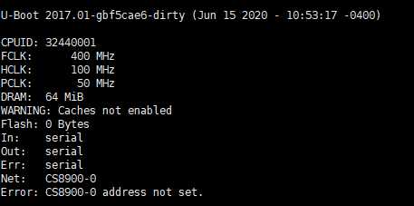
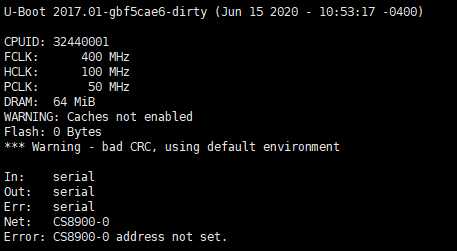
上一节中,不管是 nandflash 还是 norflash 启动,都打印了 flash: 0bytes 的字样,这说明 flash 的识别有问题:
norflash 启动的:
nandflash 启动的:
前面移植 norflash 的时候记得已经修改过,不知道是否自己的代码没上传 git ,导致这个问题。现在开始重新修改下
18.2 norflash 适配
修改调试方式:
https://www.cnblogs.com/kele-dad/p/8999684.html
https://www.cnblogs.com/kele-dad/p/12890107.html
18.3 nandflash 原理
重新回顾一下 nandflash 的原理
18.3.1 nandflash 与 s3c2440 的接口电路
大致的电路图如下:
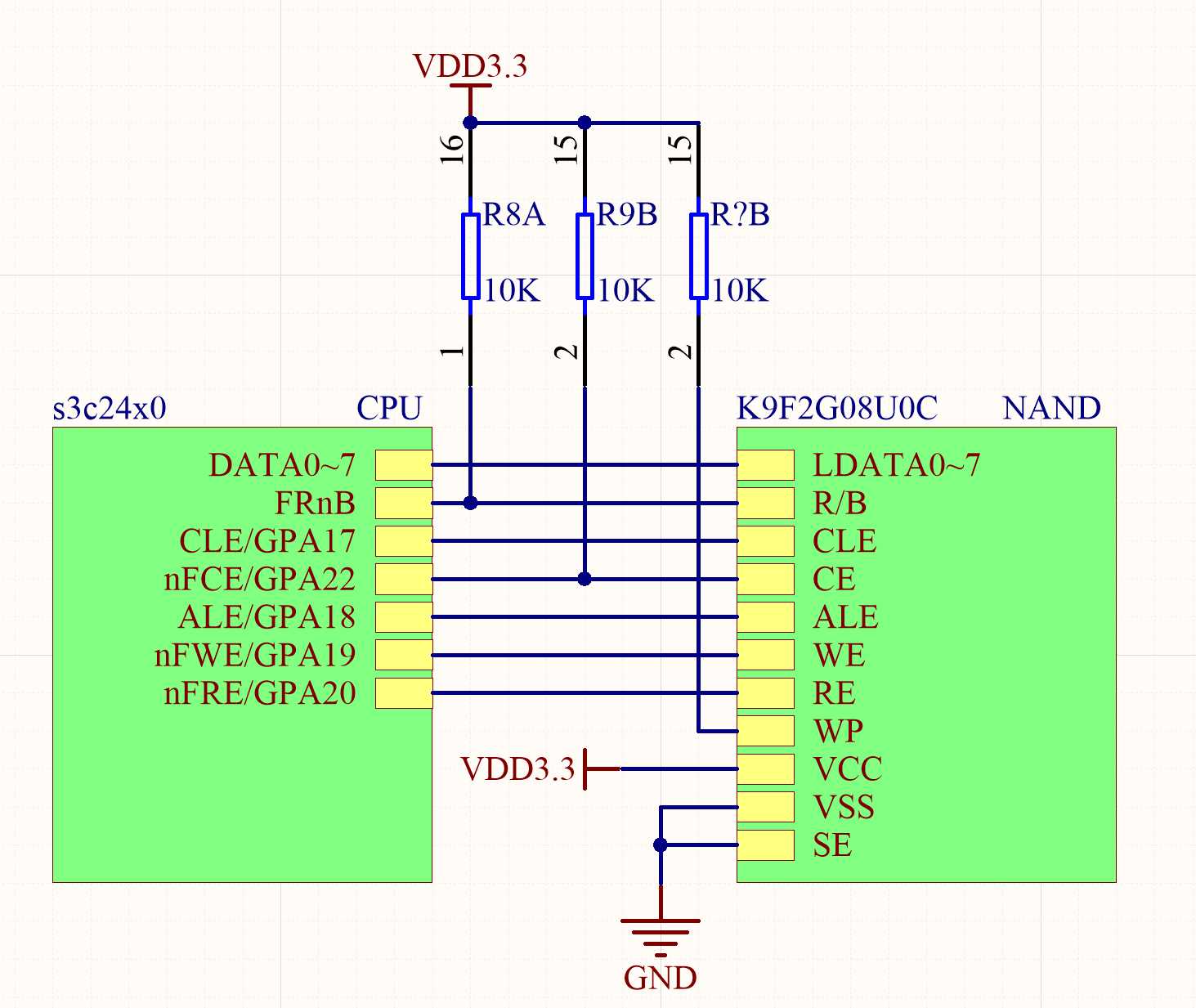
引脚含义:
| S3C2440引脚 | NandFlash 控制器含义 | K9F2G08U0C引脚 | 含义 |
| LDATA0~17 | 数据总线的0~7 | I/O0~7 | 用于传输数据/命令/地址的数据线 |
| FRnB | 用来判断NandFlash是否就绪 | R/B | 高电平表示就绪,低电平表示正在忙 |
| CLE | 用来发出命令指示信号 | CLE | 高电平表示I/O线上传输的是命令 |
| ALE | 用来发出地址指示信号 | ALE | 高电平表示I/O线上传输的是地址 |
| nFCE | 用来发出片选信号 | CE | 片选信号 |
| nFWE | 用来发出写使能信号 | WE | 写使能信号 |
| nFRE | 用来发出读使能信号 | RE | 读使能信号 |
18.3.2 nandflash 操作
看下 nandflash 的手册中的读操作的时序图(4.3节):
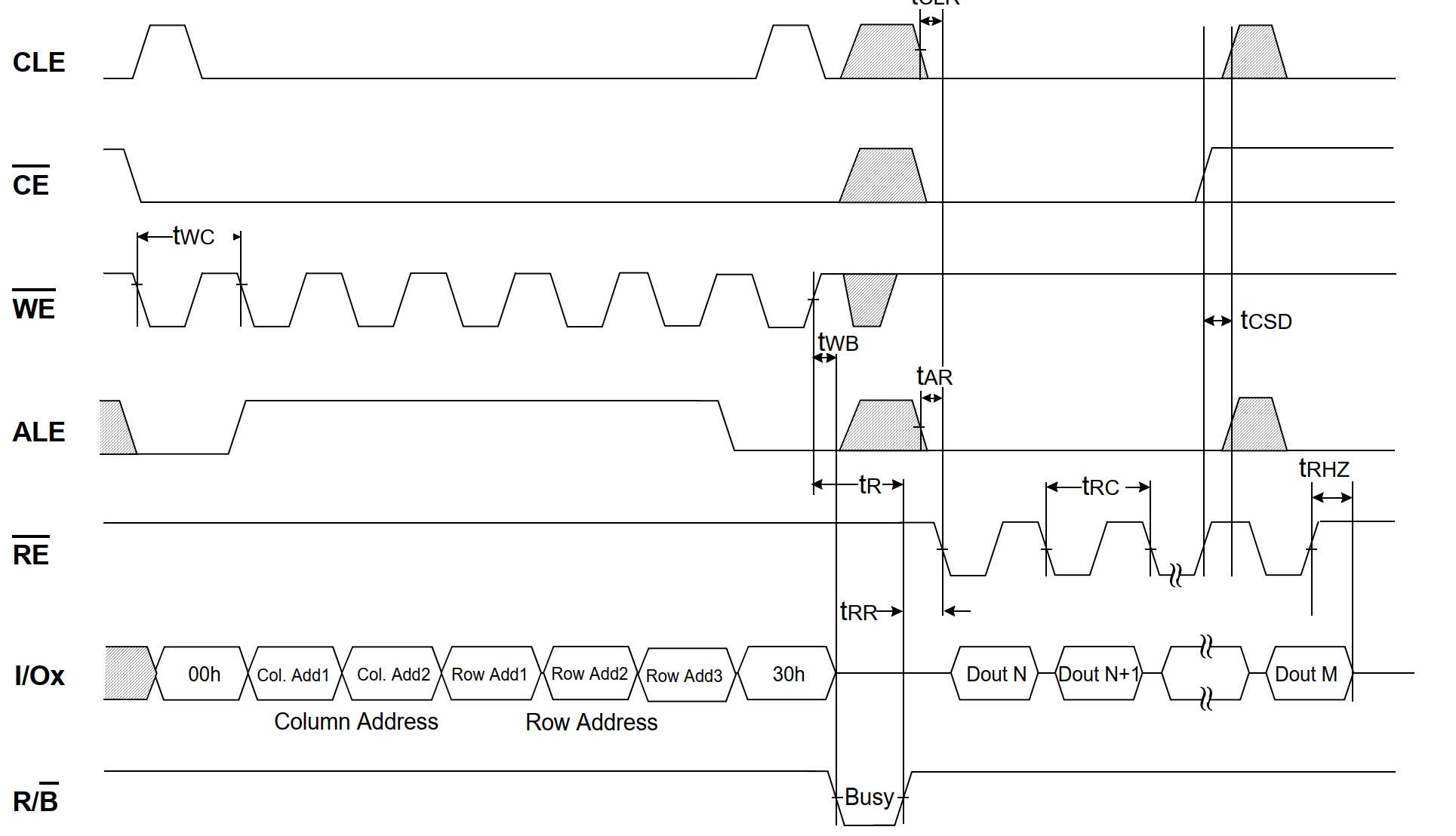
- 片选信号(CE)变为低电平后,选中 nandflash
- ALE 电平变为低,表示当前周期内不操作地址
- 检测 RB 信号,如果当前 RB 上是高电平,表示可以对 NANDFLASH 进行操作
- ALE 保持低电平,WE 第一个周期电平变化中(数据在 WE 的上升沿期间发送),CLE 信号由低电平变为高电平,表示档期那 I/Ox 即 LDATA引脚上的数据是命令 00H
- 之后,CLE重新变为低电平,不再发送命令,ALE电平拉高,开始发送地址
- 之后循环进行发送命令地址。
18.3.3 nandflash 命令集
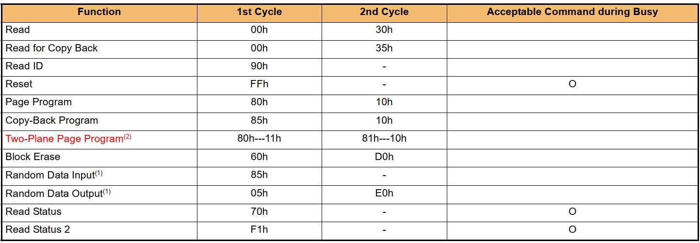
18.4 修改代码支持 nandflash
18.4.1 确定配置项
在前面的图片中,Uboot 启动没有打印 Nand 的相关选项,查看源码,board_init_r() 函数中,调用的 initr_nand() 可以知道是由配置宏 CONFIG_CMD_NAND 控制的。需要配置此宏。
追踪 initr_nand() 函数,确定代码流程,来确定还需要配置宏:
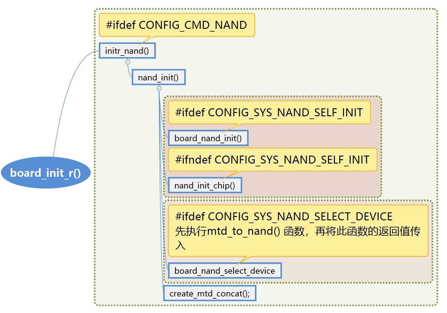
上面的uboot 总体流程图可以看到需要的配置选项:
- CONFIG_CMD_NAND:启用 NAND 支持和命令 CONFIG_SYS_NAND_SELF_INIT:调用自有的驱动进行初始化,看看 uboot 的手册怎么所的:
- 一般情况下,在 drivers/mtd/nand/nand.c 中的代码驱动了 nand 的初始化过程,这些代码提供了 mtd 和 nand 的结构,为一个特定设备调用了板载初始化函数,调用 nand_scan(),并注册进 mtd
- 这种安排没有为驱动程序提供在 nand_scan_ident() 和 nand_scan_tail() 之间运行代码的灵活性,或与正常情况不同的特殊情况
- 如果一个板定义了 CONFIG_SYS_NAND_SELF_INIT,drivers/mtd/nand/nand.c 中将调用一次 board_nand_init(),不带参数。该函数负责为主板上的每个 NAND 设备调用驱动程序的 init 函数,此函数将执行除设置 mtd->name 的所有初始化动作,之后将注册进 U-boot。最后这些任务是通过调用新的 mtd 设备上的 nand_register() 来完成的。
- 除了为驱动程序提供更大的灵活性之外,它还减少了 U-Boot 驱动程序和 Linux 驱动程序之间的差异,nand_init() 现在只调用一次 board_nand_init(),然后打印大小摘要。这也会使它更容易转换到延迟的 NAND 初始化。
- CONFIG_SYS_NAND_SELECT_DEVICE:
18.4.2 分析代码
分析之前,首先要看看 nand 的结构体和 mtd 的结构体,这两个结构体都很大,去代码 ubootincludelinuxmtd and.h 和 ubootincludelinuxmtdmtd.h 中去查看。
18.4.2.1 board_nand_init()
搜索此函数,可发现此函数都是各个开发板的 nand 芯片的自初始化代码,同样在 u-boot 代码中存在 s3c2410_nand.c 文件,此文件中包含了函数 board_nand_init() 函数,使用了 CONFIG_SYS_NAND_SELF_INIT 包含的那个函数不带入参,而 s3c2410_nand.c 中的初始化函数带参数。所以我们不能定义 CONFIG_SYS_NAND_SELF_INIT 属性,我们的代码分支也应该走 nand_init_chip() 函数。

从代码上看,需要定义一个配置宏 CONFIG_SYS_MAX_NAND_DEVICE,nand 设备的最大数量,当前 jz2440 只有一块 nand,可以将这个宏定义为 1。
nand_init_chip 执行:
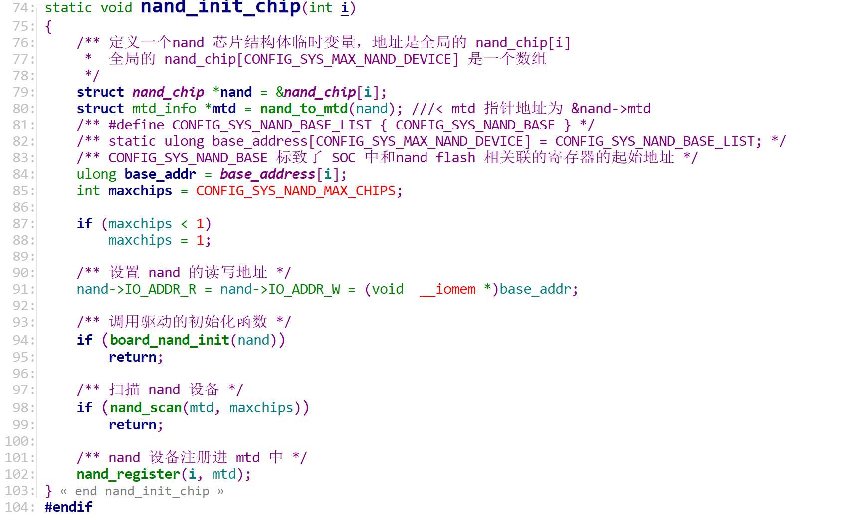
nand_init_chip 函数提供了一个新宏需要配置 CONFIG_SYS_NAND_BASE,查 CPU 手册可以知道 nand 控制器的第一个寄存器的地址是 0x4e000000(NFCONF)。
现在进入 s3c2410_nand.c 中的 board_nand_init(struct nand_chip *nand) 函数进行初始化:
 1 /**
 2  * 入参 nand 只初始化了 IO_ADDR_R 和 IO_ADDR_W,这两个值为 nand 控制器的寄存器的起始地址
 3  * nand 的地址与全局变量 nand_chip[i] 相同
 4  */
 5 int board_nand_init(struct nand_chip *nand)
 6 {
 7     u_int32_t cfg;
 8     /** 这三个变量对应 NFCONF   寄存器中的 TACLS、TWRPH0、TWRPH1
 9      *  TACLS:CLE 和 ALE 持续值设置(0 至 3) Duration = HCLK × TACLS
10      *  TWRPH0:TWRPH0 持续值设置(0~7) Duration = HCLK × ( TWRPH0 + 1 )
11      *  TWRPH1:TWRPH1 持续值设置(0~7) Duration = HCLK × ( TWRPH1 + 1 )
12      */
13     u_int8_t tacls, twrph0, twrph1;
14     /** 获取了 时钟发生器和电源管理特殊寄存器 的基地址:2410 和 2440 是0x4c000000 */
15     struct s3c24x0_clock_power *clk_power = s3c24x0_get_base_clock_power();
16     /** 获取 nand控制器寄存器的基地址,2410 和 2440 是0x4e000000  */
17     struct s3c24x0_nand *nand_reg = s3c24x0_get_base_nand();
18
19     debug("board_nand_init()
");
20
21     /** readl(&clk_power->clkcon) 读 CLKCON 寄存器, (1 << 4):1 左移动 4 位,然后两数字位或即,
22      *  即设置 CLKCON 寄存器中的 bit4 为1, bit4 为 NAND Flash Controller,
23      *  设为1 即使能进入 NAND Flash 控制器模块的 HCLK
24      */
25     writel(readl(&clk_power->clkcon) | (1 << 4), &clk_power->clkcon);
26
27     /* 设置 NANDFLASH 控制器的 NFCONF 寄存器 */
28 #if defined(CONFIG_S3C24XX_CUSTOM_NAND_TIMING)
29     tacls  = CONFIG_S3C24XX_TACLS;
30     twrph0 = CONFIG_S3C24XX_TWRPH0;
31     twrph1 =  CONFIG_S3C24XX_TWRPH1;
32 #else
33     tacls = 4;
34     twrph0 = 8;
35     twrph1 = 8;
36 #endif
37     /** 依然是 NFCONF 的初始化 */
38     cfg = S3C2410_NFCONF_EN;
39     cfg |= S3C2410_NFCONF_TACLS(tacls - 1);
40     cfg |= S3C2410_NFCONF_TWRPH0(twrph0 - 1);
41     cfg |= S3C2410_NFCONF_TWRPH1(twrph1 - 1);
42     writel(cfg, &nand_reg->nfconf);
43
44     /* initialize nand_chip data structure */
45     /** 读写寄存器指向 nand 控制器的 NFDATA 寄存器 */
46     nand->IO_ADDR_R = (void *)&nand_reg->nfdata;
47     nand->IO_ADDR_W = (void *)&nand_reg->nfdata;
48
49     nand->select_chip = NULL; ///< select_chip 函数设置为 NULL
50
51     /* read_buf and write_buf are default */
52     /* read_byte and write_byte are default */
53 #ifdef CONFIG_NAND_SPL
54     nand->read_buf = nand_read_buf;
55 #endif
56
57     /* hwcontrol always must be implemented */
58     nand->cmd_ctrl = s3c24x0_hwcontrol; ///< 控制 ALE 和 CLE 的写入
59
60     nand->dev_ready = s3c24x0_dev_ready; ///< nandflash 状态
61
62     /** ecc 初始化 */
63 #ifdef CONFIG_S3C2410_NAND_HWECC
64     nand->ecc.hwctl = s3c24x0_nand_enable_hwecc;
65     nand->ecc.calculate = s3c24x0_nand_calculate_ecc;
66     nand->ecc.correct = s3c24x0_nand_correct_data;
67     nand->ecc.mode = NAND_ECC_HW;
68     nand->ecc.size = CONFIG_SYS_NAND_ECCSIZE;
69     nand->ecc.bytes = CONFIG_SYS_NAND_ECCBYTES;
70     nand->ecc.strength = 1;
71 #else
72     nand->ecc.mode = NAND_ECC_SOFT;
73 #endif
74
75     /** 坏块存储地址 0x00020000 */
76 #ifdef CONFIG_S3C2410_NAND_BBT
77     nand->bbt_options |= NAND_BBT_USE_FLASH;
78 #endif
79
80     debug("end of nand_init
");
81
82     return 0;
83 }
18.4.2.2 nandscan
nand 初始化完成之后,要进行扫描。
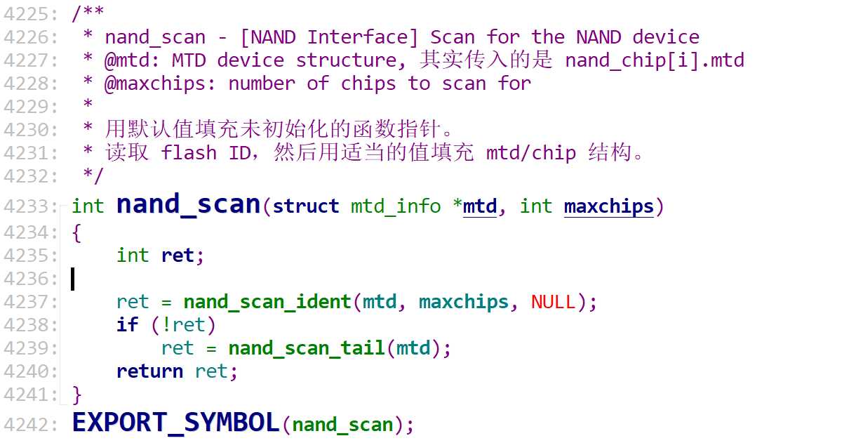
具体的设备扫描实现的第一阶段:
 1 /**
 2  * nand_scan_ident - [NAND Interface] Scan for the NAND device
 3  * @mtd: MTD device structure
 4  * @maxchips: 要扫描的芯片数量
 5  * @table: 可选的 NAND ID 表
 6  *
 7  * 这是 nand_scan() 函数的第一个阶段.它读取 flash ID 并设置相应地 MTD 字段。
 8  *
 9  */
10 int nand_scan_ident(struct mtd_info *mtd, int maxchips, struct nand_flash_dev *table)
11 {
12     int i, nand_maf_id, nand_dev_id;
13     struct nand_chip *chip = mtd_to_nand(mtd); ///< 获取 nand_chip 结构体
14     struct nand_flash_dev *type; ///< nandflash 的设备信息
15     int ret;
16
17     /** dts 设备节点中存在,则进行 dts 中的 nand 初始化 */
18     if (chip->flash_node)
19     {
20         ret = nand_dt_init(mtd, chip, chip->flash_node);
21         if (ret)
22             return ret;
23     }
24
25     /* 初始化 board_nand_init 中未初始化的函数 */
26     nand_set_defaults(chip, chip->options & NAND_BUSWIDTH_16);
27
28     /* 获取flash ID和制造商 id,并查找是否支持该类型。*/
29     type = nand_get_flash_type(mtd, chip, &nand_maf_id, &nand_dev_id, table);
30     if (IS_ERR(type)) /** 没有获取到设备 */
31     {
32         if (!(chip->options & NAND_SCAN_SILENT_NODEV))
33             pr_warn("No NAND device found
");
34         chip->select_chip(mtd, -1); ///< 关闭 nand 设备
35         return PTR_ERR(type);
36     }
37
38     chip->select_chip(mtd, -1); ///< 关闭 nand 设备
39
40     /* 检查芯片阵列 */
41     for (i = 1; i < maxchips; i++)
42     {
43         chip->select_chip(mtd, i); ///< 片选打开
44         /* 参见 nand_get_flash_type 中的注释进行重置 */
45         chip->cmdfunc(mtd, NAND_CMD_RESET, -1, -1);
46         /* 发送读取设备 ID 的命令 */
47         chip->cmdfunc(mtd, NAND_CMD_READID, 0x00, -1);
48         /* 读取制造商和设备 id */
49         if (nand_maf_id != chip->read_byte(mtd) || nand_dev_id != chip->read_byte(mtd))
50         {
51             chip->select_chip(mtd, -1);
52             break;
53         }
54         chip->select_chip(mtd, -1);
55     }
56
57 #ifdef DEBUG
58     if (i > 1)
59         pr_info("%d chips detected
", i);
60 #endif
61
62     /* 存储 nand 芯片数并为 mtd 计算总的大小 */
63     chip->numchips = i;
64     mtd->size = i * chip->chipsize;
65
66     return 0;
67 }
68 EXPORT_SYMBOL(nand_scan_ident);
扫描实现的第二阶段:nand_scan_tail,主要用于填充 ECC 操作结构体和设置 nand 的缓存区,代码太长,不贴分析ubootdriversmtd and and_base.c。
18.4.2.3 nand 注册
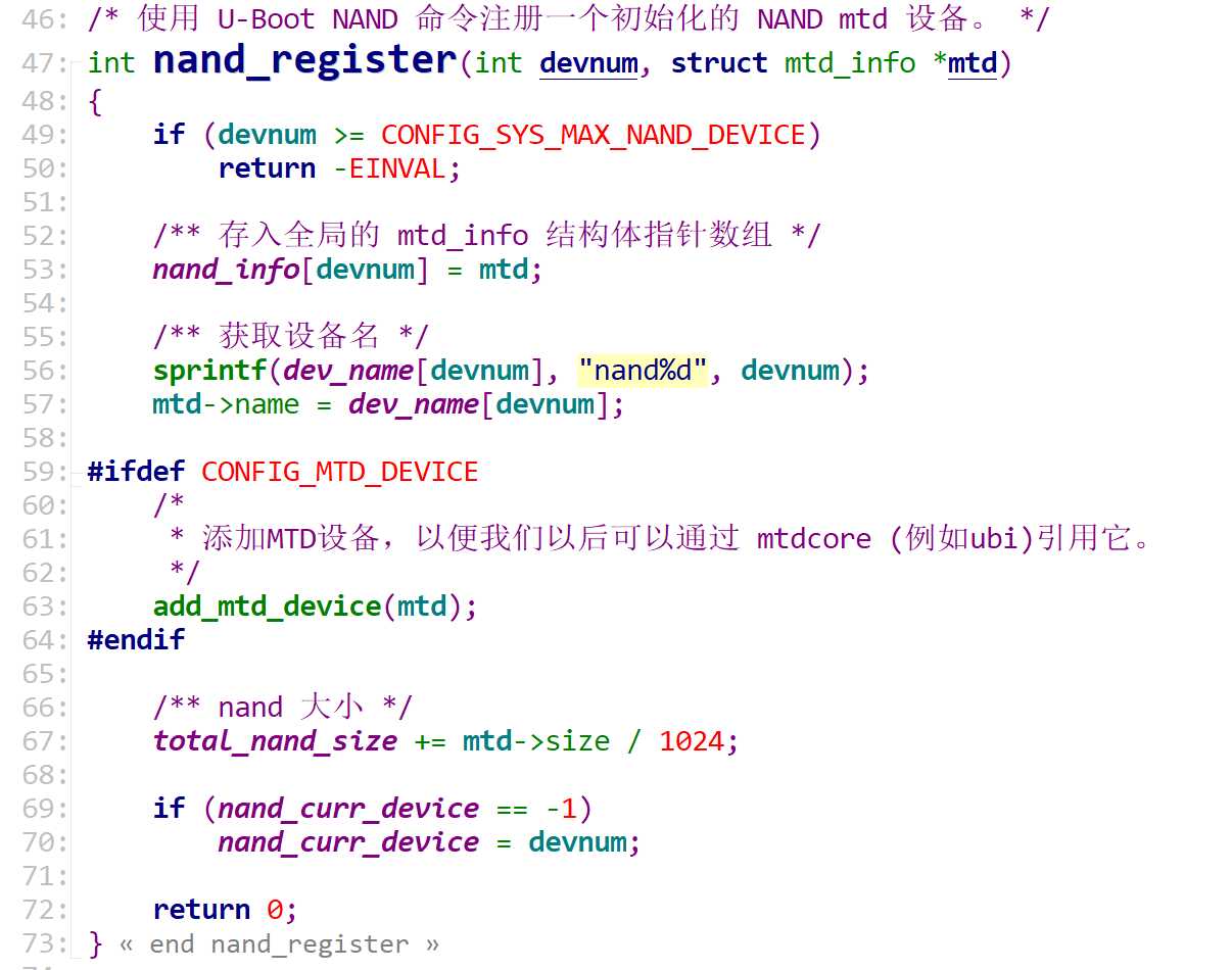
一直到此处,nandflash 的初始化流程结束。之后回到 nand_init 函数中。
18.4.2.4 board_nand_select_device

这里是针对某些特殊的 nand 芯片的。我们不相关,所以也不用开 CONFIG_SYS_NAND_SELECT_DEVICE 宏
18.4.2.5 create_mtd_concat
这个函数的作用就是建立多个 nand 的芯片的连接。有多个 nand 芯片的时候,需要开启宏 CONFIG_MTD_CONCAT
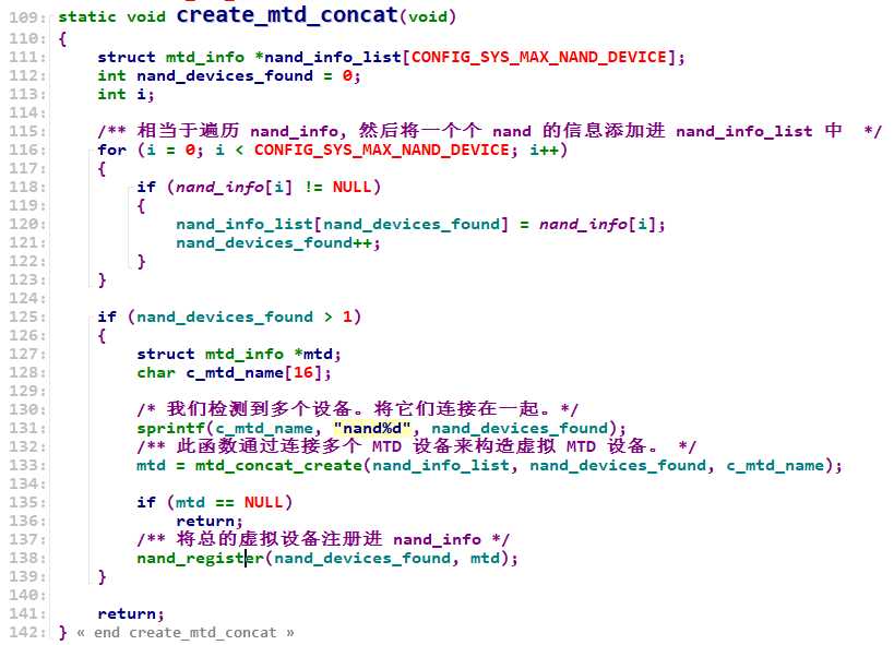
简而言之,就是将多个相同的设备合并为一个虚拟设备,然后只注册这个虚拟设备。
到现在为止,总体代码分析完毕。下一步就要进入正式移植。
以上是关于十八flash 适配的主要内容,如果未能解决你的问题,请参考以下文章