基于MCP3313-10 ADC 的SPI接口驱动练习
Posted 好记性不如烂笔头
tags:
篇首语:本文由小常识网(cha138.com)小编为大家整理,主要介绍了基于MCP3313-10 ADC 的SPI接口驱动练习相关的知识,希望对你有一定的参考价值。
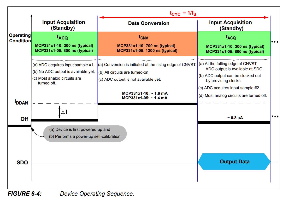
先了解MCP3313-10的操作步骤:

看上图可以了解,上电之后先经过tACQ(输入采集,但这个时候并不能对数据进行采集)一段时间,设定为状态0;再进入tCNV(数据转换期间,不能采集数据),设定为状态1;最后在进入tACQ(可以进行数据采集),设定位状态2。状态1-2-1-2之间进行轮回。
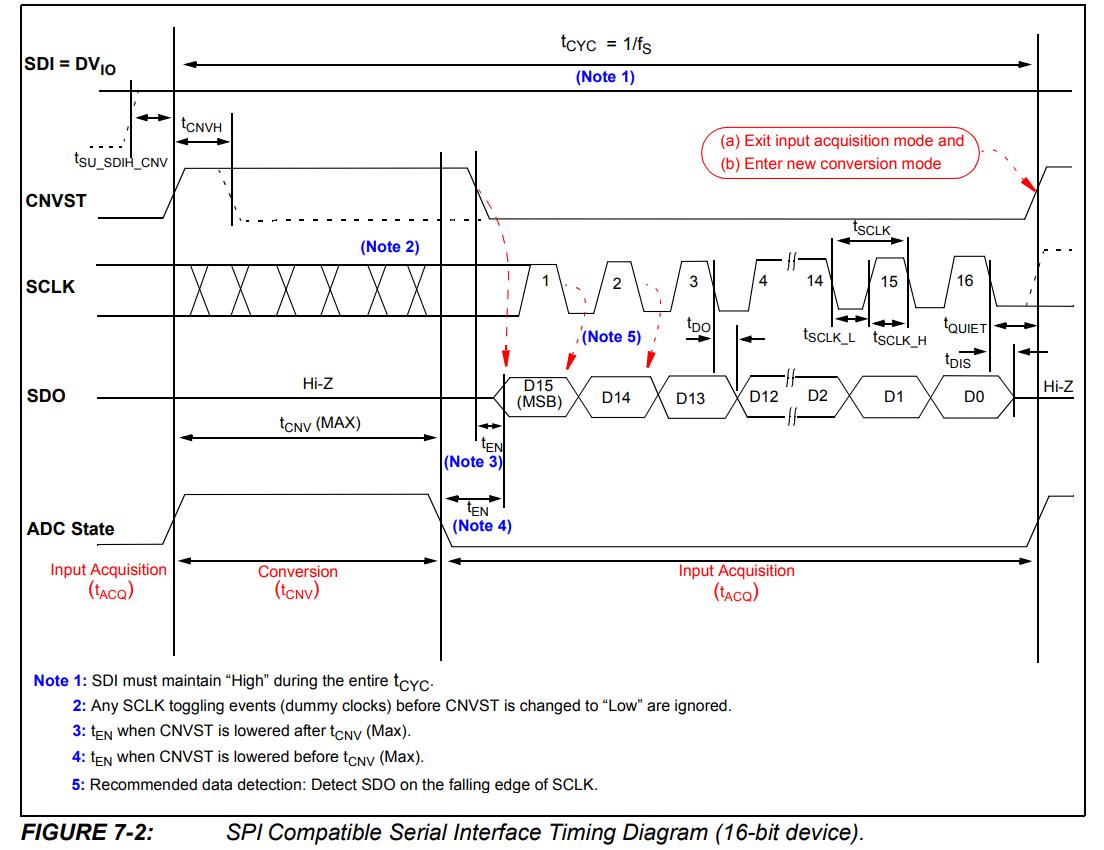
然后查看具体时序:

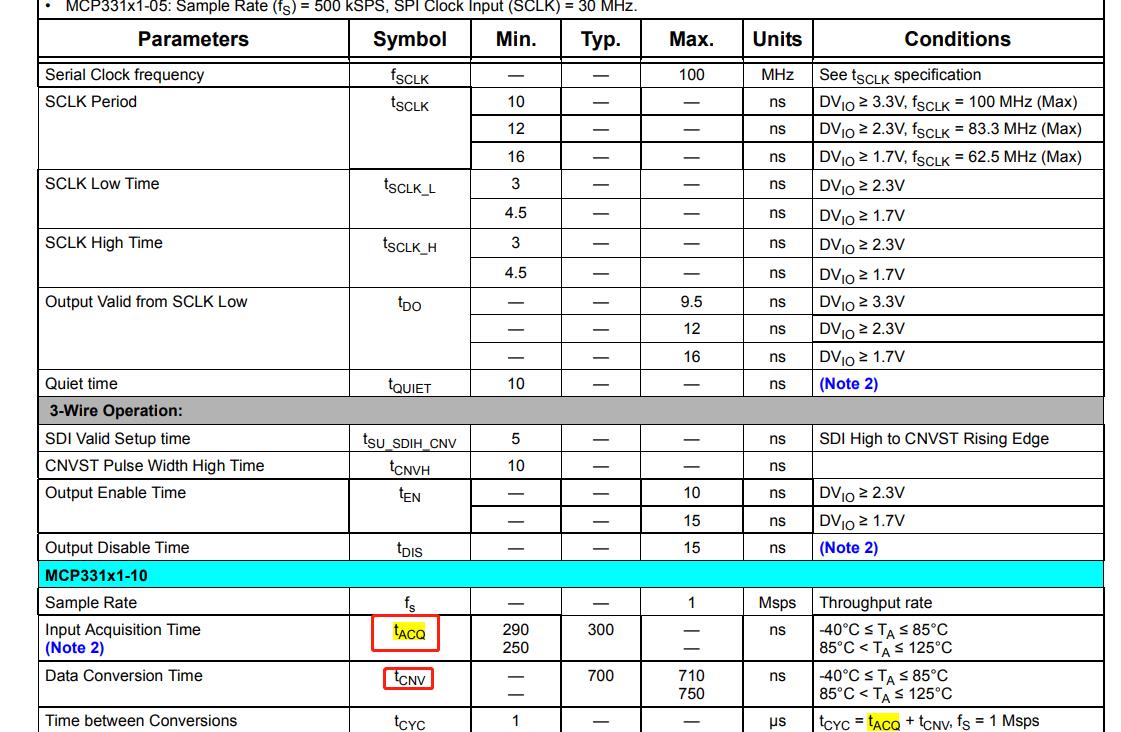
CNVST 初始值为低,经过tACQ在上升沿到来时,adc进入数据转换,转换时间需要tCNV,然后进入数据采集,采集时间tACQ,所以需要知道这几个具体时间
tACQ 有一个最小值290ns,没标最大值,说明这个时间可以更长点
tCNV有标最大值,没标最小时值,说明这个时间可以短点

OK 确认之后,可以对计数器进行设计了。一共需要两个计数器,一个计数器产生sclk,另外一个计数器需对数据采集个数进行计数。由于转换期间和数据采集期间的时间不一样,不会同时计数,所以可以重复利用一个计数器,引入一个变量x.
上电时的tACQ ,和数据转换后的tACQ 时间是一样,计数器也可以共用一个。代码如下:
 always @(posedge clk or negedge rst_n)begin
     if(!rst_n)begin
         cnt0 <= 0;
     end
     else if(add_cnt0)begin
         if(end_cnt0)begin
             cnt0 <= 0;
         end
         else begin
             cnt0 <= cnt0 + 1;
         end
     end
 end

 assign add_cnt0 = flag_add;
 assign end_cnt0 = add_cnt0 && cnt0 == 4 - 1; //输入时钟50M,4分屏,sclk = 50/4 = 12.5M

 always @(posedge clk or negedge rst_n)begin
     if(!rst_n)begin
         cnt1 <= 0;
     end
     else if(add_cnt1)begin
         if(end_cnt1)begin
             cnt1 <= 0;
         end
         else begin
             cnt1 <= cnt1 + 1;
         end
     end
 end

 assign add_cnt1 = end_cnt0;
 assign end_cnt1 = add_cnt1 && cnt1 == x - 1;

 always @(*)begin
     if(state == 0)begin
         x = 16;     //tACQ:等待16 * 80 = 1280 ns
     end
     else if(state == 1)begin
         x = 8;        //tCNV:等待8 * 80 = 640 ns ,
     end
     else begin
         x = 16;        //tACQ:等待16 * 80 = 1280 ns
     end
 end
引入了一个状态机,上电时进入state =0 状态,数据转换进入state =1 状态,数据采集进入state =2 状态
 always @(posedge clk or negedge rst_n)begin
     if(!rst_n)begin
         state <= 0;
         flag_add <= 0;
         adc_cs <= 0;
         flag_sel <= 0;
         dout_vld <= 0;
     end
     else case(state)

         0:    begin
             flag_add <= 1;
             adc_cs <= 0;
             flag_sel <= 0;
             dout_vld <= 0;
             if(end_cnt1)begin //等待16 * 80 = 1280 ns
                 state <= 1;
                 adc_cs <= 1;
                 flag_sel <= 0;
                 dout_vld <= 0;
             end
         end

         1:    begin    //adc数据在转换中
             adc_cs <= 1;
             flag_sel <= 0;
             dout_vld <= 0;
             if(end_cnt1)begin //等待8*80 = 640 ns
                 state <= 2;
                 adc_cs <= 0;
                 flag_sel <= 1;
                 dout_vld <= 0;
             end
         end

         2:    begin    // 数据采集期间
             adc_cs <= 0;
             flag_sel <= 1;
             dout_vld <= 0;
             if(end_cnt1)begin //等待16 * 80 = 1280 ns,数据采集完进入下一轮转换
                 state <= 1;
                 adc_cs <= 1;
                 flag_sel <= 0;
                 dout_vld <= 1;
             end
         end

         default: state <= 0;
     endcase
 end
引入了几个信号:
flag_add: 计数器启动条件,这里设置为1,计数器一直计数
flag_sel:将数据采集那段时间进行标注,用于区分哪段时间需要进行采数据
dout_vld:数据采集完产生一个有效标志,然后对一个完整数据进行锁存
 always @(posedge clk or negedge rst_n)begin
     if(!rst_n)begin
         adc_data_temp <= 0;
     end
     else if(flag_sel == 1 && add_cnt0 && cnt0 == 2-1 && cnt1 >= 0 && cnt1 < 16)begin //在sclk的下降沿采数据,同时在flag_sel有效期间
             adc_data_temp[15-cnt1] <= adc_sdo;
     end
 end

 always @(posedge clk or negedge rst_n)begin
     if(!rst_n)begin
         adc_data <= 0;
     end
     else if(dout_vld)begin //一个完整的16bit数据采集完
         adc_data <= adc_data_temp;
     end
 end
然后产生sclk时钟:
 always @(posedge clk or negedge rst_n)begin
     if(!rst_n)begin
         adc_sclk <= 1;
     end
     else if(add_cnt0 && cnt0 == 2-1)begin
         adc_sclk <= 0;
     end
     else if(end_cnt0)begin
         adc_sclk <= 1;
     end
 end
完整代码:


 module mcp3313_10_test(
                     clk,
                     rst_n,
                     adc_sdo,

                     adc_cs,
                     adc_sclk,
                     adc_data
 );

 input     clk;
 input     rst_n;
 input     adc_sdo;

 output                 adc_cs;
 output                 adc_sclk;
 output     [16-1 : 0]    adc_data;

 reg     [16-1 : 0]     adc_data_temp;
 reg     [16-1 : 0]    adc_data;
 reg     [3 -1 : 0]     cnt0/* synthesis keep*/;
 reg     [6 -1 : 0]     cnt1/* synthesis keep*/;
 reg     [6 -1 : 0]     x/* synthesis keep*/;
 reg     [2 -1 : 0]     state/* synthesis keep*/;
 reg                    flag_add;
 reg                    flag_sel;
 reg                 dout_vld;
 reg                 adc_cs;
 reg                 adc_sclk;


 wire                 add_cnt0;
 wire                 end_cnt0;
 wire                 add_cnt1;
 wire                 end_cnt1;

 always @(posedge clk or negedge rst_n)begin
     if(!rst_n)begin
         cnt0 <= 0;
     end
     else if(add_cnt0)begin
         if(end_cnt0)begin
             cnt0 <= 0;
         end
         else begin
             cnt0 <= cnt0 + 1;
         end
     end
 end

 assign add_cnt0 = flag_add;
 assign end_cnt0 = add_cnt0 && cnt0 == 4 - 1; //输入时钟50M,4分屏,sclk = 50/4 = 12.5M

 always @(posedge clk or negedge rst_n)begin
     if(!rst_n)begin
         cnt1 <= 0;
     end
     else if(add_cnt1)begin
         if(end_cnt1)begin
             cnt1 <= 0;
         end
         else begin
             cnt1 <= cnt1 + 1;
         end
     end
 end

 assign add_cnt1 = end_cnt0;
 assign end_cnt1 = add_cnt1 && cnt1 == x - 1;

 always @(*)begin
     if(state == 0)begin
         x = 16;     //tACQ:等待16 * 80 = 1280 ns
     end
     else if(state == 1)begin
         x = 8;        //tCNV:等待8 * 80 = 640 ns ,
     end
     else begin
         x = 16;        //tACQ:等待16 * 80 = 1280 ns
     end
 end

 always @(posedge clk or negedge rst_n)begin
     if(!rst_n)begin
         state <= 0;
         flag_add <= 0;
         adc_cs <= 0;
         flag_sel <= 0;
         dout_vld <= 0;
     end
     else case(state)

         0:    begin
             flag_add <= 1;
             adc_cs <= 0;
             flag_sel <= 0;
             dout_vld <= 0;
             if(end_cnt1)begin //等待16 * 80 = 1280 ns
                 state <= 1;
                 adc_cs <= 1;
                 flag_sel <= 0;
                 dout_vld <= 0;
             end
         end

         1:    begin    //adc数据在转换中
             adc_cs <= 1;
             flag_sel <= 0;
             dout_vld <= 0;
             if(end_cnt1)begin //等待8*80 = 640 ns
                 state <= 2;
                 adc_cs <= 0;
                 flag_sel <= 1;
                 dout_vld <= 0;
             end
         end

         2:    begin    // 数据采集期间
             adc_cs <= 0;
             flag_sel <= 1;
             dout_vld <= 0;
             if(end_cnt1)begin //等待16 * 80 = 1280 ns,数据采集完进入下一轮转换
                 state <= 1;
                 adc_cs <= 1;
                 flag_sel <= 0;
                 dout_vld <= 1;
             end
         end

         default: state <= 0;
     endcase
 end

 always @(posedge clk or negedge rst_n)begin
     if(!rst_n)begin
         adc_data_temp <= 0;
     end
     else if(flag_sel == 1 && add_cnt0 && cnt0 == 2-1 && cnt1 >= 0 && cnt1 < 16)begin //在sclk的下降沿采数据,同时在flag_sel有效期间
             adc_data_temp[15-cnt1] <= adc_sdo;
     end
 end

 always @(posedge clk or negedge rst_n)begin
     if(!rst_n)begin
         adc_data <= 0;
     end
     else if(dout_vld)begin //一个完整的16bit数据采集完
         adc_data <= adc_data_temp;
     end
 end

 always @(posedge clk or negedge rst_n)begin
     if(!rst_n)begin
         adc_sclk <= 1;
     end
     else if(add_cnt0 && cnt0 == 2-1)begin
         adc_sclk <= 0;
     end
     else if(end_cnt0)begin
         adc_sclk <= 1;
     end
 end

 endmodule
SignalTap II Logic Analyzer 抓取波形如下:

以上是关于基于MCP3313-10 ADC 的SPI接口驱动练习的主要内容,如果未能解决你的问题,请参考以下文章