基于QPSK调制和CoSaMP算法的信道估计均衡算法matlab仿真
Posted 51matlab
tags:
篇首语:本文由小常识网(cha138.com)小编为大家整理,主要介绍了基于QPSK调制和CoSaMP算法的信道估计均衡算法matlab仿真相关的知识,希望对你有一定的参考价值。
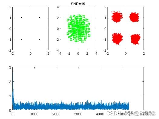
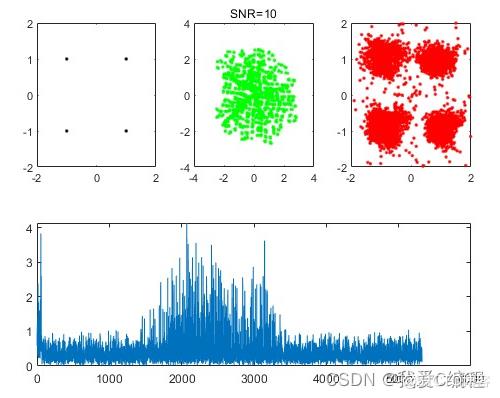
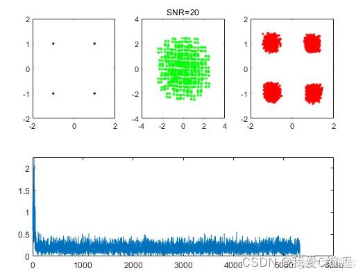
1.算法仿真效果
matlab2022a仿真结果如下:


2.算法涉及理论知识概要
均衡器的分类
• 均衡处理方法
时域均衡器:单载波数字通信中多采用时域均衡器,从时域的冲激响应考虑
正交频分复用OFDM调制:采用频域均衡
• 是否使用训练序列或导频
DA(数据辅助)
DD(判决指向)
NDA(盲均衡):需要在接收到足够多的数据情况下才能得到一个可靠的估计
导频或训练序列的插入
地面数字电视一般使用DA方式信道估计和均衡
• 多径衰落信道可以看成是在时间和频率上的一个二维信号
• 训练序列时域的间隔取决于信道的相关时间
• 训练序列频域的间隔取决于相关带宽
• 训练序列对信道在时-频空间的不同点上进行采样,利用采样插值即可得到整个信道的频率响应值
时域均衡器
• 均衡器的输出是否用于反馈控制
线性均衡器:输出未被用于反馈控制
非线性均衡器:输出用于反馈,如判决反馈均衡器(DFE-decision Feedback Equalizer)
• 线性均衡器
均衡器(Equalizer),是一种可以分别调节各种频率成分电信号放大量的电子设备,通过对各种不同频率的电信号的调节来补偿扬声器和声场的缺陷,补偿和修饰各种声源及其它特殊作用,一般调音台上的均衡器仅能对高频、中频、低频三段频率电信号分别进行调节。
在通信系统中,在基带系统中插入均衡器能够减小码间干扰的影响。均衡器(equalizer) 通信系统中,校正传输信道幅度频率特性和相位频率特性的部件。将频率为f的正弦波送入传输信道,输出电压与输入电压的幅度比随f变化的特性称为幅度频率特性,简称幅频特性;输出电压与输入电压间的相位差随f变化的特性称为相位频率特性,简称相频特性。
所谓信道估计,发送端发送已知的、预定义的序列(输入),然后接收端从接收序列拟数据中(输出),将假定的某个信道模型的模型参数(信道衰变模型),估计出来的过程。
如果信道是线性的话,那么信道估计就是对系统冲激响应进行估计。
需强调的是信道估计是信道对输入信号影响的一种数学表示,而“好”的信道估计则是使得某种估计误差最小化的估计算法。
PN码(Pseudo-Noise Code),是一具有与白噪声类似的自相关性质的0和1所构成的编码序列,最广为人知的二位元P-N Code是最大长度位移暂存器序列,简称m-序列, 他具有长 2的N次方 - 1个位元。
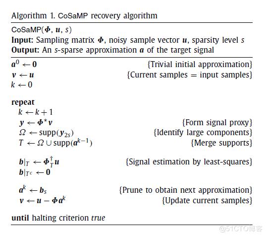
压缩采样匹配追踪(CompressiveSampling MP)是D. Needell继ROMP之后提出的又一个具有较大影响力的重构算法。CoSaMP也是对OMP的一种改进,每次迭代选择多个原子,除了原子的选择标准之外,它有一点不同于ROMP:ROMP每次迭代已经选择的原子会一直保留,而CoSaMP每次迭代选择的原子在下次迭代中可能会被抛弃。

3.MATLAB核心程序
SNR            = 30;

train_code_num = 500;
info_code_num  = 5000;
code_num       = train_code_num + info_code_num;
[ src_codes ]  = bitsgen( code_num );


[ response_codes ] = channel( 21,128,SNR,src_codes );

.............................................................
figure
subplot(2,3,1)
plot(I,Q,\'b.\',...
    \'LineWidth\',1,...
    \'MarkerSize\',6,...
    \'MarkerEdgeColor\',\'k\',...
    \'MarkerFaceColor\',[0.0,0.9,0.0]);
axis([-2,2,-2,2])
I = real(response_codes(train_code_num+1:end-FrontOrder+1))/std(real(response_codes(train_code_num+1:end-FrontOrder+1)));
Q = imag(response_codes(train_code_num+1:end-FrontOrder+1))/std(imag(response_codes(train_code_num+1:end-FrontOrder+1)));

subplot(2,3,2)
plot(I,Q,\'b.\',...
    \'LineWidth\',1,...
    \'MarkerSize\',6,...
    \'MarkerEdgeColor\',\'g\',...
    \'MarkerFaceColor\',[0.0,0.9,0.0]);
axis([-4,4,-4,4])
I = real(am_xEst(train_code_num+1:end))/std(real(am_xEst(train_code_num+1:end)));
Q = imag(am_xEst(train_code_num+1:end))/std(imag(am_xEst(train_code_num+1:end)));
title([\'SNR=\',num2str(SNR)])
subplot(2,3,3)
plot(I,Q,\'b.\',...
    \'LineWidth\',1,...
    \'MarkerSize\',6,...
    \'MarkerEdgeColor\',\'r\',...
    \'MarkerFaceColor\',[0.0,0.9,0.0]);
axis([-2,2,-2,2])

subplot(2,3,[4,5,6])
plot(ee);
盲信道估计基于matlab的LMS盲信道估计QPSK仿真
目录
1.软件版本
MATLAB2021a
2.核心代码
% CHANNEL EQUALIZATION USING LMS
clc;
clear all;
close all;
M=3000;    % number of data samples
T=2000;    % number of training symbols
dB=25;     % SNR in dB value

L=20; % length for smoothing(L+1)
ChL=5;  % length of the channel(ChL+1)
EqD=round((L+ChL)/2);  %delay for equalization

Ch=randn(1,ChL+1)+sqrt(-1)*randn(1,ChL+1);   % complex channel
Ch=Ch/norm(Ch);                     % scale the channel with norm

TxS=round(rand(1,M))*2-1;  % QPSK transmitted sequence
TxS=TxS+sqrt(-1)*(round(rand(1,M))*2-1);


x=filter(Ch,1,TxS);  %channel distortion
n=randn(1,M);  %+sqrt(-1)*randn(1,M);   %Additive white gaussian noise
 n=n/norm(n)*10^(-dB/20)*norm(x);  % scale the noise power in accordance with SNR
x=x+n;                           % received noisy signal

K=M-L;   %% Discarding several starting samples for avoiding 0's and negative
X=zeros(L+1,K);  % each vector column is a sample
for i=1:K
    X(:,i)=x(i+L:-1:i).';
end

%adaptive LMS Equalizer
e=zeros(1,T-10);  % initial error
c=zeros(L+1,1);   % initial condition
mu=0.001;        % step size
for i=1:T-10
    e(i)=TxS(i+10+L-EqD)-c'*X(:,i+10);   % instant error
    c=c+mu*conj(e(i))*X(:,i+10);           % update filter or equalizer coefficient
end

sb=c'*X;   % recieved symbol estimation

%SER(decision part)
sb1=sb/norm(c);  % normalize the output
sb1=sign(real(sb1))+sqrt(-1)*sign(imag(sb1));  %symbol detection
start=7;
sb2=sb1-TxS(start+1:start+length(sb1));  % error detection
SER=length(find(sb2~=0))/length(sb2); %  SER calculation
disp(SER);

% plot of transmitted symbols
    subplot(2,2,1),
    plot(TxS,'*');
    grid,title('Input symbols');  xlabel('real part'),ylabel('imaginary part')
    axis([-2 2 -2 2])

% plot of received symbols
    subplot(2,2,2),
    plot(x,'o');
    grid, title('Received samples');  xlabel('real part'), ylabel('imaginary part')

% plots of the equalized symbols
    subplot(2,2,3),
    plot(sb,'o');
    grid, title('Equalized symbols'), xlabel('real part'), ylabel('imaginary part')

% convergence
    subplot(2,2,4),
    plot(abs(e));
    grid, title('Convergence'), xlabel('n'), ylabel('error signal')
    %%

    %IMPLEMENTATION OF BLIND CHANNEL USING CMA OR GODARD ALGORITHM IMPLEMENTED

clc;
clear all;
close all;
N=3000;    % number of sample data
dB=25;     % Signal to noise ratio(dB)

L=20; % smoothing length L+1
ChL=1;  % length of the channel= ChL+1
EqD=round((L+ChL)/2);  %  channel equalization delay

i=sqrt(-1);
%Ch=randn(1,ChL+1)+sqrt(-1)*randn(1,ChL+1);   % complex channel

%Ch=[0.0545+j*0.05 .2832-.1197*j -.7676+.2788*j -.0641-.0576*j .0566-.2275*j .4063-.0739*j];
Ch=[0.8+i*0.1 .9-i*0.2]; %complex channel
    Ch=Ch/norm(Ch);% normalize
TxS=round(rand(1,N))*2-1;  % QPSK symbols are transmitted symbols
TxS=TxS+sqrt(-1)*(round(rand(1,N))*2-1);
x=filter(Ch,1,TxS); %channel distortion

n=randn(1,N)+sqrt(-1)*randn(1,N);   % additive white gaussian noise (complex)
 n=n/norm(n)*10^(-dB/20)*norm(x);  % scale noise power
x1=x+n;  % received noisy signal

...................
3.操作步骤与仿真结论

4.参考文献
[1]陈国军, 胡捍英. OFDM系统自适应盲信道估计新方法[J]. 信号处理, 2013, 29(6):5.
D228
5.完整源码获得方式
方式1:微信或者QQ联系博主
方式2:订阅MATLAB/FPGA教程,免费获得教程案例以及任意2份完整源码
以上是关于基于QPSK调制和CoSaMP算法的信道估计均衡算法matlab仿真的主要内容,如果未能解决你的问题,请参考以下文章