Huawei VRRP+MSTP组网实验-ensp
Posted 陌熊
tags:
篇首语:本文由小常识网(cha138.com)小编为大家整理,主要介绍了Huawei VRRP+MSTP组网实验-ensp相关的知识,希望对你有一定的参考价值。
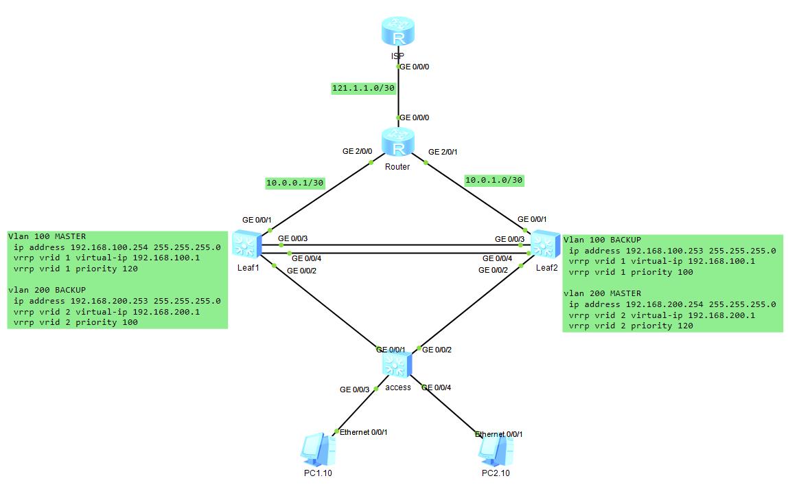
一、基本环境
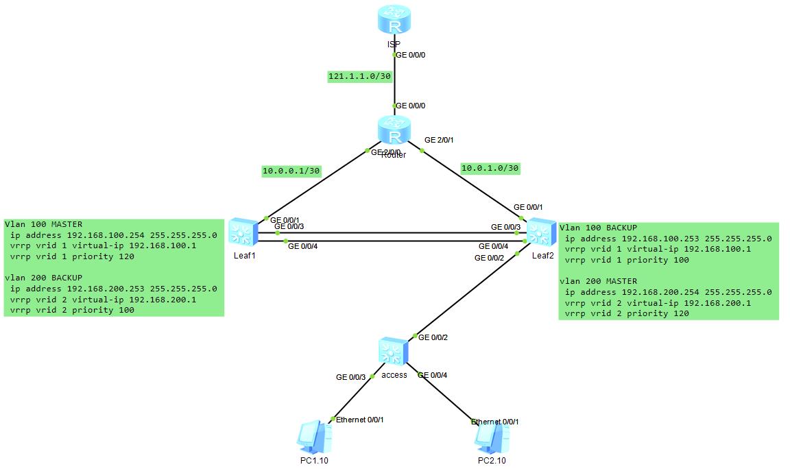
IP地址规划:
- 互联网公网IP地址:
Router:121.1.1.0/30 - 内网互联地址:
Leaf1:10.0.0.0/30
Leaf2:10.0.1.0/30 - 内网vlan网关:
vlan 100 :192.168.100.1 24
vlan 200 :192.168.200.1 24
二、拓扑结构
三、实验配置
出口网关
ISP网络配置
[ISP]interface GigabitEthernet 0/0/0
[ISP-GigabitEthernet0/0/0]ip add 121.1.1.1 30
[ISP-GigabitEthernet0/0/0]quit
Router网络配置
[Router]acl 2000
[Router-acl-basic-2000]rule 5 permit source any
[Router-GigabitEthernet0/0/0]nat outbound 2000
[Router]interface GigabitEthernet 0/0/0
[Router-GigabitEthernet0/0/0]ip add 121.1.1.2 30
[Router-GigabitEthernet0/0/0]quit
[Router]interface GigabitEthernet 0/0/1
[Router-GigabitEthernet0/0/1]interface GigabitEthernet 2/0/1
[Router-GigabitEthernet2/0/1]ip add 10.0.1.1 30
[Router-GigabitEthernet2/0/1]quit
[Router]interface GigabitEthernet 2/0/0
[Router-GigabitEthernet2/0/0]ip add 10.0.0.1 30
[Router-GigabitEthernet2/0/0]quit
[Router]ip route-static 0.0.0.0 0 121.1.1.1
[Router]ip route-static 192.168.100.0 24 10.0.0.2
[Router]ip route-static 192.168.100.0 24 10.0.1.2
[Router]ip route-static 192.168.200.0 24 10.0.1.2
[Router]ip route-static 192.168.200.0 24 10.0.0.2
内网上联
Leaf1配置
[Leaf2]vlan 1000
[Leaf2-vlan1000]quit
[Leaf1-vlan1000]int vlan 1000
[Leaf1-Vlanif1000]ip address 10.0.0.2 30
[Leaf1]interface GigabitEthernet 0/0/1
[Leaf1-GigabitEthernet0/0/1]port link-type access
[Leaf1-GigabitEthernet0/0/1]port default vlan 1000
[Leaf1]ip route-static 0.0.0.0 0 10.0.0.1
Leaf2配置
[Leaf2]vlan 1000
[Leaf2-vlan1000]quit
[Leaf2]interface vlan 1000
[Leaf2-Vlanif1000]ip address 10.0.1.2 30
[Leaf2-Vlanif1000]quit
[Leaf2]interface GigabitEthernet 0/0/1
[Leaf2-GigabitEthernet0/0/1]port link-type access
[Leaf2-GigabitEthernet0/0/1]port default vlan 1000
[Leaf2]ip route-static 0.0.0.0 0 10.0.1.1
VRRP配置
Leaf1配置
[Leaf1]vlan batch 100 200
[Leaf1-Vlanif100]ip add 192.168.100.254 24
[Leaf1-Vlanif100]vrrp vrid 1 virtual-ip 192.168.100.1
[Leaf1-Vlanif100]vrrp vrid 1 track interface GigabitEthernet 0/0/1 reduced 30
[Leaf1-Vlanif100]vrrp vrid 1 priority 120
[Leaf1]interface vlan 200
[Leaf1-Vlanif200]ip address 192.168.200.253 255.255.255.0
[Leaf1-Vlanif200]vrrp vrid 2 virtual-ip 192.168.200.1
[Leaf1-Vlanif200]vrrp vrid 2 priority 100
# 配置主备vrrp设备聚合链路
[Leaf1]interface Eth-Trunk 1
[Leaf2-Eth-Trunk1]port link-type trunk
[Leaf2-Eth-Trunk1]port trunk allow-pass vlan all
[Leaf1-Eth-Trunk1]trunkport GigabitEthernet 0/0/3
[Leaf1-Eth-Trunk1]trunkport GigabitEthernet 0/0/4
Leaf2配置
[Leaf2]vlan batch 100 200
[Leaf2-Vlanif100]ip add 192.168.100.253 24
[Leaf2-Vlanif100]vrrp vrid 1 virtual-ip 192.168.100.1
[Leaf2-Vlanif100]vrrp vrid 1 priority 120
[Leaf2]interface vlan 200
[Leaf2-Vlanif200]ip address 192.168.200.254 255.255.255.0
[Leaf2-Vlanif200]vrrp vrid 2 virtual-ip 192.168.200.1
[Leaf2-Vlanif200]vrrp vrid 2 priority 120
[Leaf2-Vlanif200]vrrp vrid 2 track interface GigabitEthernet 0/0/1 reduced 30
# 配置主备vrrp设备聚合链路
[Leaf2]interface Eth-Trunk 1
[Leaf2-Eth-Trunk1]port link-type trunk
[Leaf2-Eth-Trunk1]port trunk allow-pass vlan all
[Leaf2-Eth-Trunk1]trunkport GigabitEthernet 0/0/3
[Leaf2-Eth-Trunk1]trunkport GigabitEthernet 0/0/4
MSTP配置
Leaf1配置
[leaf1]stp enable
[Leaf1]stp mode mstp
[Leaf1]stp region-configuration
[Leaf1-mst-region]instance 1 vlan 100
[Leaf1-mst-region]instance 2 vlan 200
[Leaf1-mst-region]active region-configuration
[Leaf1]stp instance 1 root primary
[Leaf1]stp instance 2 root secondary
Leaf2配置
[leaf2]stp enable
[Leaf2]stp mode mstp
[Leaf2]stp region-configuration
[Leaf2-mst-region]instance 1 vlan 100
[Leaf2-mst-region]instance 2 vlan 200
[Leaf2-mst-region]active region-configuration
[Leaf2]stp instance 1 root secondary
[Leaf2]stp instance 2 root primary
access配置
[access]stp enable
[access]stp mode mstp
[access]stp region-configuration
[access-mst-region]instance 1 vlan 100
[access-mst-region]instance 2 vlan 200
[access-mst-region]active region-configuration
内网下联
Leaf1配置
[Leaf1]interface GigabitEthernet 0/0/2
[Leaf1-GigabitEthernet0/0/2]port trunk allow-pass vlan 100 200
[Leaf1-GigabitEthernet0/0/2]undo port trunk allow-pass vlan 1
Leaf2配置
[Leaf2]interface GigabitEthernet 0/0/2
[Leaf2-GigabitEthernet0/0/2]port trunk allow-pass vlan 100 200
[Leaf2-GigabitEthernet0/0/2]undo port trunk allow-pass vlan 1
access配置
[access]interface GigabitEthernet 0/0/3
[access-GigabitEthernet0/0/3]port link-type access
[access-GigabitEthernet0/0/3]port default vlan 100
[access-GigabitEthernet0/0/3]stp edged-port enable
[access-GigabitEthernet0/0/3]quit
[access]interface GigabitEthernet 0/0/4
[access-GigabitEthernet0/0/4]port link-type access
[access-GigabitEthernet0/0/4]port default vlan 200
[access-GigabitEthernet0/0/4]stp edged-port enable
[access-GigabitEthernet0/0/4]quit
[access]interface GigabitEthernet 0/0/1
[access-GigabitEthernet0/0/1]port trunk allow-pass vlan 100 200
[access-GigabitEthernet0/0/1]undo port trunk allow-pass vlan 1
[access]interface GigabitEthernet 0/0/2
[access-GigabitEthernet0/0/2]port trunk allow-pass vlan 100 200
[access-GigabitEthernet0/0/2]undo port trunk allow-pass vlan 1
终端测试
配置PC1.10的地址为100.10
配置PC2.10的地址为200.10
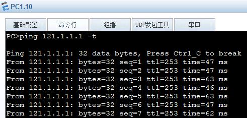
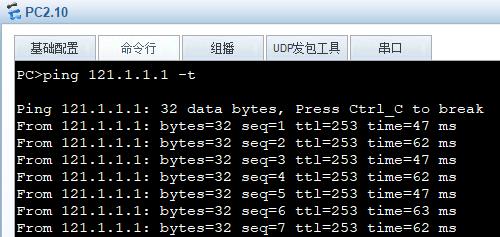
链路完整下测试
两台PC都可以访问互联网
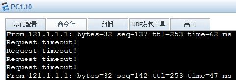
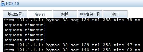
断开Leaf上联口
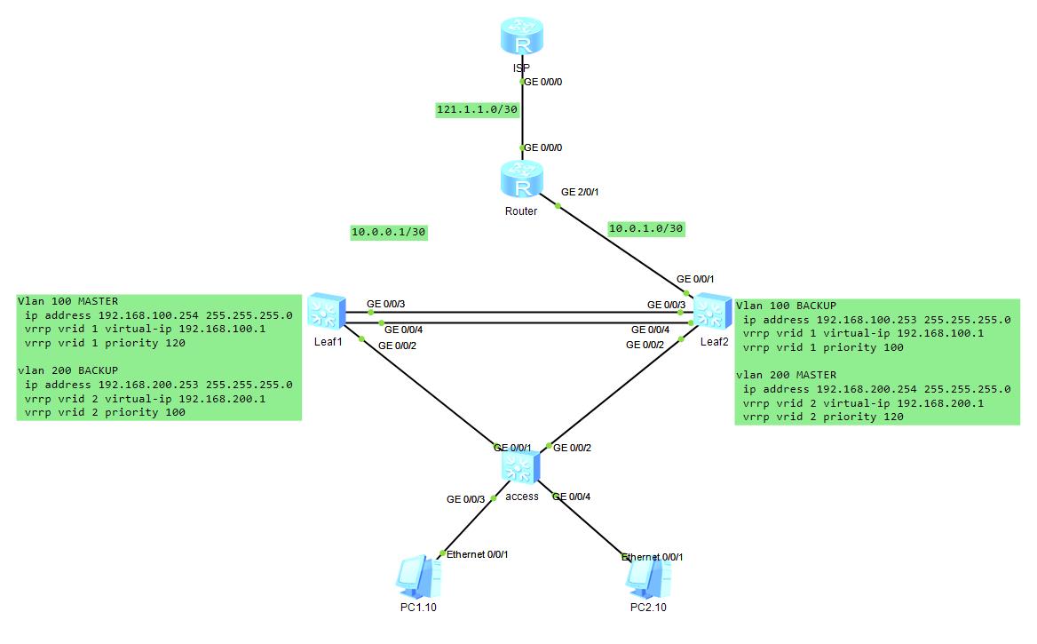
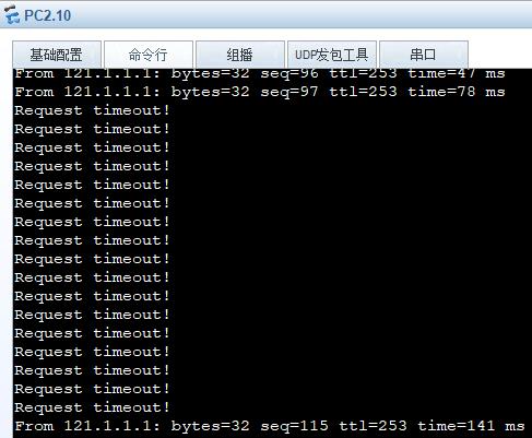
PC1在掉4个包后恢复
PC2在掉4个包后恢复
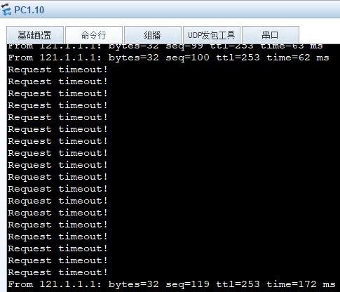
断开Leaf下联口
PC丢包后恢复
PC2丢包后恢复
玩转华为ENSP模拟器系列 | 配置MSTP功能示例
素材来源:华为路由器配置指南
一边学习一边整理试验笔记,并与大家分享,侵权即删,谢谢支持!
附上汇总贴:玩转华为ENSP模拟器系列 | 合集_COCOgsta的博客-CSDN博客_ensp实验大全
组网需求
在一个复杂的网络中,由于冗余备份的需要,网络规划者一般都倾向于在设备之间部署多条物理链路,其中一条作为主用链路,其他作为备份链路。这样就难免会形成环路,若网络中存在环路,可能会引起广播风暴和MAC表项被破坏。为此,可以在网络中部署MSTP协议预防环路。MSTP可阻塞二层网络中的冗余链路,将网络修剪成树状,达到消除环路的目的。
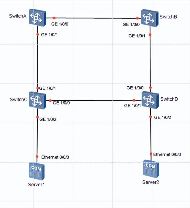
如图1所示,SwitchA、SwitchB、SwitchC和SwitchD都运行MSTP。为实现VLAN2~VLAN10和VLAN11~VLAN20的流量负载分担,MSTP引入了多实例。MSTP可设置VLAN映射表,把VLAN和生成树实例相关联。
配置思路
- 在处于环形网络中的交换设备上配置MSTP基本功能。
- 配置保护功能,实现对设备或链路的保护。例如:在各实例的根桥设备指定端口配置根保护功能。
- 配置设备的二层转发功能。
操作步骤
- 配置MSTP基本功能 配置SwitchA、SwitchB、SwitchC和SwitchD到域名为RG1的域内,创建实例MSTI1和实例MSTI2
# 配置SwitchA的MST域。
stp region-configuration
 region-name RG1
 instance 1 vlan 2 to 10
 instance 2 vlan 11 to 20
# 配置SwitchB的MST域。
stp region-configuration
 region-name RG1
 instance 1 vlan 2 to 10
 instance 2 vlan 11 to 20
# 配置SwitchC的MST域。
stp region-configuration
 region-name RG1
 instance 1 vlan 2 to 10
 instance 2 vlan 11 to 20
# 配置SwitchD的MST域。
stp region-configuration
 region-name RG1
 instance 1 vlan 2 to 10
 instance 2 vlan 11 to 20
- 在域RG1内,配置MSTI1与MSTI2的根桥与备份根桥
- 配置MSTI1的根桥与备份根桥
# 配置SwitchA为MSTI1的根桥。
stp instance 1 root primary
# 配置SwitchB为MSTI1的备份根桥。
stp instance 1 root secondary
- 配置MSTI2的根桥与备份根桥
# 配置SwitchB为MSTI2的根桥。
stp instance 2 root primary
# 配置SwitchA为MSTI2的备份根桥。
stp instance 2 root secondary
- 配置实例MSTI1和MSTI2中将要被阻塞端口的路径开销值大于缺省值
# 配置SwitchA的端口路径开销值的计算方法为华为计算方法。
stp pathcost-standard legacy
# 配置SwitchB的端口路径开销计算方法为华为计算方法。
stp pathcost-standard legacy
# 配置SwitchC的端口路径开销计算方法为华为计算方法,将端口GE1/0/0在实例MSTI2中的路径开销值配置为20000。
stp pathcost-standard legacy
interface GE1/0/0
 stp instance 2 cost 20000
# 配置SwitchD的端口路径开销计算方法为华为计算方法,将端口GE1/0/2在实例MSTI1中的路径开销值配置为20000。
stp pathcost-standard legacy
interface GE1/0/1
 stp instance 1 cost 20000
- 使能MSTP,实现破除环路
- 设备全局使能MSTP
# 在SwitchA上启动MSTP。
stp enable
# 在SwitchB上启动MSTP。
stp enable
# 在SwitchC上启动MSTP。
stp enable
# 在SwitchD上启动MSTP。
stp enable
- 将与终端相连的端口去使能MSTP
# 配置SwitchC端口GE1/0/2的STP去使能。
interface GE1/0/2
 stp disable
# 配置SwitchD端口GE1/0/2的STP去使能。
interface GE1/0/2
 stp disable
- 配置保护功能,如在各实例的根桥设备的指定端口配置根保护功能
# 在SwitchA端口GE1/0/1上启动根保护。
interface GE1/0/1
 stp root-protection
# 在SwitchB端口GE1/0/1上启动根保护。
interface GE1/0/1
 stp root-protection
- 配置处于环网中的设备的二层转发功能
- 在交换设备SwitchA、SwitchB、SwitchC和SwitchD上创建VLAN2~20
# 在SwitchA上创建VLAN2~20。
vlan batch 2 to 20
# 在SwitchB上创建VLAN2~20。
vlan batch 2 to 20
# 在SwitchC上创建VLAN2~20。
vlan batch 2 to 20
# 在SwitchD上创建VLAN2~20。
vlan batch 2 to 20
- 将交换设备上接入环路中的端口加入VLAN
# 将SwitchA端口GE1/0/1加入VLAN。
interface GE1/0/1
 port link-type trunk
 port trunk allow-pass vlan 2 to 20
# 将SwitchA端口GE1/0/0加入VLAN。
interface GE1/0/0
 port link-type trunk
 port trunk allow-pass vlan 2 to 20
# 将SwitchB端口GE1/0/1加入VLAN。
interface GE1/0/1
 port link-type trunk
 port trunk allow-pass vlan 2 to 20
# 将SwitchB端口GE1/0/0加入VLAN。
interface GE1/0/0
 port link-type trunk
 port trunk allow-pass vlan 2 to 20
# 将SwitchC端口GE1/0/2加入VLAN。
interface GE1/0/2
 port link-type access
 port default vlan 2
# 将SwitchC端口GE1/0/0加入VLAN。
interface GE1/0/0
 port link-type trunk
 port trunk allow-pass vlan 2 to 20
# 将SwitchC端口GE1/0/1加入VLAN。
interface GE1/0/1
 port link-type trunk
 port trunk allow-pass vlan 2 to 20
# 将SwitchD端口GE1/0/2加入VLAN。
interface GE1/0/2
 port link-type access
 port default vlan 11
# 将SwitchD端口GE1/0/1加入VLAN。
interface GE1/0/1
 port link-type trunk
 port trunk allow-pass vlan 2 to 20
# 将SwitchD端口GE1/0/0加入VLAN。
interface GE1/0/0
 port link-type trunk
 port trunk allow-pass vlan 2 to 20
- 验证配置结果
在网络计算稳定后,执行以下操作,验证配置结果。
# 在SwitchA上执行display stp brief命令,查看端口状态和端口的保护类型,结果如下:
[~SwitchA]dis stp bri
 MSTID  Port                        Role  STP State     Protection      Cost
Edged
     0  GE1/0/0                     ROOT  forwarding    none             199
disable
     0  GE1/0/1                     DESI  discarding    root             199
disable
     1  GE1/0/0                     DESI  forwarding    none             199
disable
     1  GE1/0/1                     DESI  forwarding    root             199
disable
     2  GE1/0/0                     ROOT  forwarding    none             199
disable
     2  GE1/0/1                     DESI  forwarding    root             199
disable
[~SwitchA]
在MSTI1中,由于SwitchA是根桥,SwitchA的端口GE1/0/0和GE1/0/1成为指定端口。在MSTI2中,SwitchA的端口GE1/0/1成为指定端口,端口GE1/0/0成为根端口。
# 在SwitchB上执行display stp brief命令,结果如下:
[~SwitchB]dis stp bri
 MSTID  Port                        Role  STP State     Protection      Cost
Edged
     0  GE1/0/0                     DESI  forwarding    none             199
disable
     0  GE1/0/1                     DESI  discarding    root             199
disable
     1  GE1/0/0                     ROOT  forwarding    none             199
disable
     1  GE1/0/1                     DESI  forwarding    root             199
disable
     2  GE1/0/0                     DESI  forwarding    none             199
disable
     2  GE1/0/1                     DESI  forwarding    root             199
disable
[~SwitchB]
在MSTI2中,由于SwitchB是根桥,端口GE1/0/1和GE1/0/0在MSTI2中成为指定端口。在MSTI1中,SwitchB的端口GE1/0/1成为指定端口,端口GE1/0/0成为根端口。
# 在SwitchC上执行display stp interface brief命令,结果如下:
[~SwitchC]dis stp interface ge 1/0/1 brief
 MSTID  Port                        Role  STP State     Protection      Cost
Edged
     0  GE1/0/1                     DESI  forwarding    none             199
disable
     1  GE1/0/1                     ROOT  forwarding    none             199
disable
     2  GE1/0/1                     ROOT  forwarding    none             199
disable
[~SwitchC]
[~SwitchC]dis stp interface ge 1/0/0 brief
 MSTID  Port                        Role  STP State     Protection      Cost
Edged
     0  GE1/0/0                     ROOT  forwarding    none             199
disable
     1  GE1/0/0                     DESI  forwarding    none             199
disable
     2  GE1/0/0                     ALTE  discarding    none           20000
disable
[~SwitchC]
SwitchC的端口GE1/0/1在MSTI1和MSTI2中为根端口。SwitchC的另一个端口GE1/0/0,在MSTI2中被阻塞,在MSTI1中被计算为指定端口。
# 在SwitchD上执行display stp interface brief命令,结果如下:
[~SwitchD]dis stp interface  ge 1/0/0 brief
 MSTID  Port                        Role  STP State     Protection      Cost
Edged
     0  GE1/0/0                     DESI  forwarding    none             199
disable
     1  GE1/0/0                     ROOT  forwarding    none             199
disable
     2  GE1/0/0                     ROOT  forwarding    none             199
disable
[~SwitchD]dis stp interface  ge 1/0/1 brief
 MSTID  Port                        Role  STP State     Protection      Cost
Edged
     0  GE1/0/1                     DESI  forwarding    none             199
disable
     1  GE1/0/1                     ALTE  discarding    none           20000
disable
     2  GE1/0/1                     DESI  forwarding    none             199
disable
[~SwitchD]
SwitchD的端口GE1/0/0在MSTI1和MSTI2中为根端口。SwitchD的另一个端口GE1/0/1,在MSTI1中被阻塞,在MSTI2中被计算为指定端口。
 开发者涨薪指南
 48位大咖的思考法则、工作方式、逻辑体系
以上是关于Huawei VRRP+MSTP组网实验-ensp的主要内容,如果未能解决你的问题,请参考以下文章