单片机AT89C51各个引脚的作用都有哪些?
Posted
tags:
篇首语:本文由小常识网(cha138.com)小编为大家整理,主要介绍了单片机AT89C51各个引脚的作用都有哪些?相关的知识,希望对你有一定的参考价值。
参考技术A VCC/GND:供电电源。\\x0d\\x0aP0口:可以被定义为数据/地址的低八位,能够用于外部程序/数据存储器。在FIASH编程时,P0 口作为原码输入口,当FIASH进行校验时,P0输出原码,此时P0外部必须被拉高。\\x0d\\x0aP1口:标准输入输出I/O,P1口管脚写入1后,被内部上拉为高,可用作输入。在FLASH编程和校验时,P1口作为第八位地址接收。 P2口:既可用于标准输入输出I/O,也可用于外部程序存储器或数据存储器访问时的高八位地址。P2口在FLASH编程和校验时接收高八位地址信号和控制信号。P3口:既可以作标准输入输出I/O,也可作为AT89C51的一些特殊功能口, 管脚 备选功能\\x0d\\x0aP3.0 RXD(串行输入口)\\x0d\\x0aP3.1 TXD(串行输出口)\\x0d\\x0aP3.2 /INT0(外部中断0)\\x0d\\x0aP3.3 /INT1(外部中断1)\\x0d\\x0aP3.4 T0(记时器0外部输入)\\x0d\\x0aP3.5 T1(记时器1外部输入)\\x0d\\x0aP3.6 /WR(外部数据存储器写选通)\\x0d\\x0aP3.7 /RD(外部数据存储器读选通)\\x0d\\x0aRST:复位输入。当振荡器复位器件时,要保持RST脚两个机器周期的高电平时间。\\x0d\\x0aALE/PROG:当访问外部存储器时,地址锁存允许的输出电平用于锁存地址的地位字节。在FLASH编程期间,此引脚用于输入编程脉冲。在平时,ALE端以不变的频率周期输出正脉冲信号,此频率为振荡器频率的1/6。/PSEN:外部程序存储器的选通信号。在由外部程序存储器取指期间,每个机器周期两次/PSEN有效。但在访问外部数据存储器时,这两次有效的/PSEN信号将不出现。\\x0d\\x0a/EA / VPP:当/EA保持低电平时,则在此期间外部程序存储器(0000H-FFFFH),不管是否有内部程序存储器。注意加密方式1时,/EA将内部锁定为RESET;当/EA端保持高电平时,此间内部程序存储器。在FLASH编程期间,此引脚也用于施加12V编程电源(VPP)。\\x0d\\x0aXTAL1:反向振荡放大器的输入及内部时钟工作电路的输入。\\x0d\\x0aXTAL2:来自反向振荡器的输出。LINUX子系统之pinctrl子系统
简单介绍
像以前我们在开发单片机的时候就经常涉及到引脚的配置,如果更换了pin脚就需要重新配置下引脚,规范点的做法就是将引脚用宏定义定义,当需要某个引脚时只需要修改宏定义即可,不用全局更换,在Linux中引入了pinctrl子系统,**pinctrl子系统的作用就是负责引脚的复用(用作什么功能)、配置(open drain等)和引脚的枚举命名(支持哪些引脚)其定义主要由function(用作什么功能,IIC(要不要上拉?)?UART?)和group(用哪几组引脚?PINA1和PINA2?)组成.**在设备树中我们使用pinctrl节点的节点称为client.
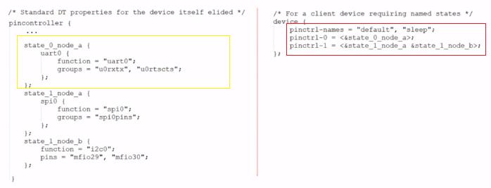
如上图黄色方框的部分为pinctrl子系统的一个节点,红色方框为它的client,也就是使用它的设备,可以看出pinctrl节点中有function和groups,对于不同的IC厂,使用的语法不一样但是对于内涵还是一致的,对于右边的client引用了该节点,且在不同的状态下对应了不同的pinctrl节点,即不同状态下对应不用的工作模式。
主要数据结构介绍
如图1所示,根据Linux中面向对象的特点,**会将pincontroller抽象出一个pinctrl_dev结构体,将device抽象出device结构体,这个device结构体里面肯定会有一个pinctrl成员和pinctrl_dev挂钩。**那么该如何去构造出这个pinctrl_dev?答案就是设置,分配,设置,注册一个pinctrl_desc结构体
/**
 * struct pinctrl_desc - pin controller descriptor, register this to pin
 * control subsystem
 * @name: name for the pin controller
 * @pins: an array of pin descriptors describing all the pins handled by
 *	this pin controller
 * @npins: number of descriptors in the array, usually just ARRAY_SIZE()
 *	of the pins field above
 * @pctlops: pin control operation vtable, to support global concepts like
 *	grouping of pins, this is optional.
 * @pmxops: pinmux operations vtable, if you support pinmuxing in your driver
 * @confops: pin config operations vtable, if you support pin configuration in
 *	your driver
 * @owner: module providing the pin controller, used for refcounting
 * @num_custom_params: Number of driver-specific custom parameters to be parsed
 *	from the hardware description
 * @custom_params: List of driver_specific custom parameters to be parsed from
 *	the hardware description
 * @custom_conf_items: Information how to print @params in debugfs, must be
 *	the same size as the @custom_params, i.e. @num_custom_params
 */
struct pinctrl_desc
	const char *name;
	const struct pinctrl_pin_desc *pins;
	unsigned int npins;
	const struct pinctrl_ops *pctlops;
	const struct pinmux_ops *pmxops;
	const struct pinconf_ops *confops;
	struct module *owner;
#ifdef CONFIG_GENERIC_PINCONF
	unsigned int num_custom_params;
	const struct pinconf_generic_params *custom_params;
	const struct pin_config_item *custom_conf_items;
#endif
;
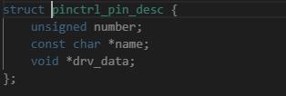
pins:结构体数组,number表示第几个引脚,name表示引脚的名字,drv_data表示驱动相关的数据,描述单个引脚
npins:表示多少个引脚,描述单个引脚
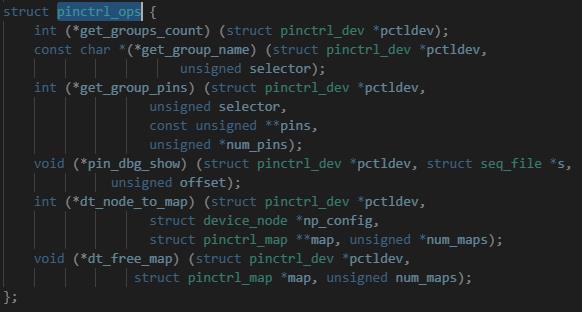
pctlops:它可以去获得有多少组引脚,获得某一组的多个引脚,描述多个引脚,比如get_group_pins函数获取某个pinctrl控制器的第selector引脚,这些引脚会保存在pins里面,有多少个可以保存在num_pins里面.该结构体里面的函数主要处理一组里面的引脚
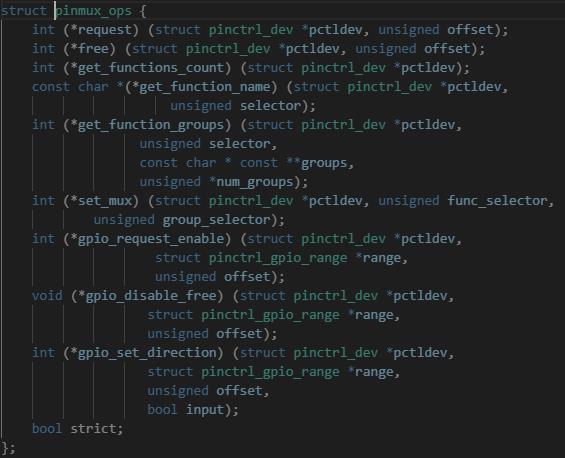
pmxops:对于获取一组里面的引脚可以用pctlops里面的函数来实现,对于需要配置成什么功能就需要该结构体里面的函数来实现.比如set_mux函数就是把某一组引脚配置成某一功能
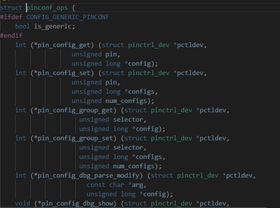
pinconf_ops:用于引脚的配置,如上下拉等
可以看出我们说的pinctrl的三大作用:引脚枚举命名(pins,npins),引脚复用(pctlops,pmxops),引脚配置(pinconf_ops)就在上面实现了
构造过程
根据Linux平台设备驱动的套路,肯定会匹配pincontroller节点的compatible属性且该节点会转化为一个平台设备,进而调用driver的probe函数,以imx6ull为例子,如代码所示
int imx_pinctrl_probe(struct platform_device *pdev,
		      struct imx_pinctrl_soc_info *info)

	...........
	imx_pinctrl_desc = devm_kzalloc(&pdev->dev, sizeof(*imx_pinctrl_desc),
					GFP_KERNEL);//分配
	if (!imx_pinctrl_desc)
		return -ENOMEM;
	/*设置*/
	imx_pinctrl_desc->name = dev_name(&pdev->dev);
	imx_pinctrl_desc->pins = info->pins;
	imx_pinctrl_desc->npins = info->npins;
	imx_pinctrl_desc->pctlops = &imx_pctrl_ops;
	imx_pinctrl_desc->pmxops = &imx_pmx_ops;
	imx_pinctrl_desc->confops = &imx_pinconf_ops;
	imx_pinctrl_desc->owner = THIS_MODULE;
    ........
	/*注册*/
	ipctl->pctl = devm_pinctrl_register(&pdev->dev,
					    imx_pinctrl_desc, ipctl);
	.......
	return 0;
可以看出分配,设置,注册完之后会返回一个pinctrl_dev类型的结构体,用来表示pincontroller.
Client端的使用过程

如图1所示,黄色方框是我们的使用pinctroller的client,对于这个节点肯定会转化成一个平台设备,该设备会继承一个struct_device结构体,在该结构体里面会有struct dev_pin_info类型的变量,可以看出该结构对应各种state,那么肯定就是用到黄色方框里面的pinctrl-names,pinctrl-0包含的信息来构造了.我们也可以看出仅仅有上面那几个状态是不够的,那么我们使用其他状态该怎么办呢?就要使用到struct pinctrl这个数据结构了,可以看出该结构有一个链表头用以存放各种state,我们可以将相应的状态填充进去,包括我们自己定义的一些状态!
那么这些xxx_state从哪里构造呢?就需要从图1黄色方框中的pinctroller中的子节点来构造这些state.
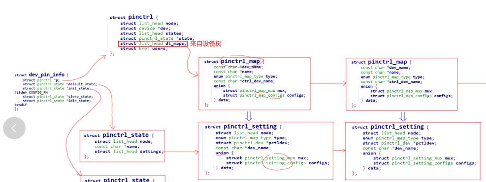
对于pinctroller中的子节点,会调用pctlops中的dt_node_to_map函数来转化为pinctrl_map,pinctrl_map转化为pinctrl_setting,
pinctrl_setting会存入pinctrl_state.setting链表中,这样当我们切换到某个状态时就可以在states头节点的链表中找到对应的pinctrl_state,然后根据pinctrl_state下的setting链表配置,复用引脚(信息来自于struct pinctrl_setting,调用pctlops中的set_mux等函数),下面请看切换过程
int pinctrl_select_state(struct pinctrl *p, struct pinctrl_state *state)

	struct pinctrl_setting *setting, *setting2;
	struct pinctrl_state *old_state = p->state;
	int ret;

	if (p->state == state)
		return 0;

	if (p->state)
		/*
		 * For each pinmux setting in the old state, forget SW's record
		 * of mux owner for that pingroup. Any pingroups which are
		 * still owned by the new state will be re-acquired by the call
		 * to pinmux_enable_setting() in the loop below.
		 */
		list_for_each_entry(setting, &p->state->settings, node)
			if (setting->type != PIN_MAP_TYPE_MUX_GROUP)
				continue;
			pinmux_disable_setting(setting);


	p->state = NULL;

	/* Apply all the settings for the new state */
	list_for_each_entry(setting, &state->settings, node)
		switch (setting->type)
		case PIN_MAP_TYPE_MUX_GROUP:
			ret = pinmux_enable_setting(setting);
			break;
		case PIN_MAP_TYPE_CONFIGS_PIN:
		case PIN_MAP_TYPE_CONFIGS_GROUP:
			ret = pinconf_apply_setting(setting);
			break;
		default:
			ret = -EINVAL;
			break;


		if (ret < 0)
			goto unapply_new_state;


	p->state = state;

	return 0;

unapply_new_state:
	dev_err(p->dev, "Error applying setting, reverse things back\\n");

	list_for_each_entry(setting2, &state->settings, node)
		if (&setting2->node == &setting->node)
			break;
		/*
		 * All we can do here is pinmux_disable_setting.
		 * That means that some pins are muxed differently now
		 * than they were before applying the setting (We can't
		 * "unmux a pin"!), but it's not a big deal since the pins
		 * are free to be muxed by another apply_setting.
		 */
		if (setting2->type == PIN_MAP_TYPE_MUX_GROUP)
			pinmux_disable_setting(setting2);


	/* There's no infinite recursive loop here because p->state is NULL */
	if (old_state)
		pinctrl_select_state(p, old_state);

	return ret;
我们可以看到其实就是遍历state下的一个setting链表,然后根据当前的一个状态完成配置.
note:
list_for_each_entry(setting, &state->settings, node)
等同于
for (setting = list_entry((&state->settings)->next, typeof(*setting), node);
&setting->node != (&state->settings);
setting = list_entry(setting->node.next, typeof(*setting), node))
list_entry((&state->settings)->next, typeof(*setting), node)
等同
container_of((&state->settings)->next, typeof(*setting), node)宏解释:https://www.cnblogs.com/linhaostudy/p/7966081.html
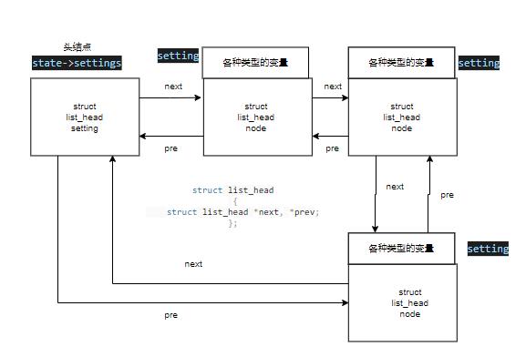
对于state->settings其实就是setting链表的头结点,这是一个state状态下维持的一个
setting链表头,可以看出该for循环可以看成三部分
1.setting = list_entry((&state->settings)->next, typeof(*setting), node)
返回的其实就是setting这个entry,next是因为linux是双向循环链表,所以头节点不带数据
得从头节点的下一个节点开始
2.当遍历到的setting节点的头节点和setiing当前节点一致就退出,说明走了一遍了
3.继续遍历下一个节点
以上是关于单片机AT89C51各个引脚的作用都有哪些?的主要内容,如果未能解决你的问题,请参考以下文章