NanoPi NEO Air使用十二:使用自带的fbtft驱动点亮SPI接口TFT屏幕,ST7789V
Posted 【ql君】qlexcel
tags:
篇首语:本文由小常识网(cha138.com)小编为大家整理,主要介绍了NanoPi NEO Air使用十二:使用自带的fbtft驱动点亮SPI接口TFT屏幕,ST7789V相关的知识,希望对你有一定的参考价值。
上节自己编写spi驱动来点亮spi接口的小屏幕,其实Linux内核里已经提供spi接口小屏的设备驱动,即内核中已经自带了此类驱动,名字为fbtft。本节就来使用它。
引脚
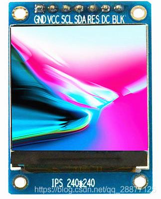
240x240分辨率,1.3寸,主控为ST7789VW。
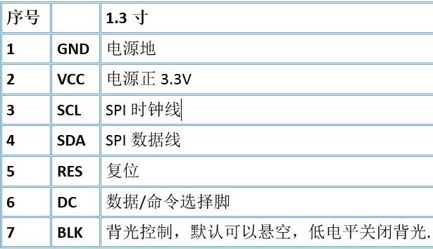
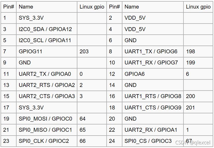
与开发板的引脚连接确定如下:
| 功能 | IO |
|---|---|
| GND | Pin6 |
| 5V | Pin2 |
| LCD_RESET | Pin7-PG11 |
| LCD_DC | Pin22-PA1 |
| SPICLK | Pin23-PC2 |
| SPIMOSI | Pin19-PC0 |
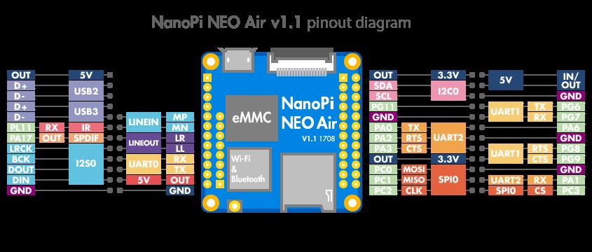
从开发板的引脚图发现,开发板使用的SPI0。
修改设备树
打开/home/ql/linux/H3/linux/arch/arm/boot/dts/sun8i-h3-nanopi.dtsi,找到spi0节点,修改为如下:
&spi0
	/* needed to avoid dtc warning */
	#address-cells = <1>;
	#size-cells = <0>;

	status = "okay";
	pinctrl-names = "default";
	pinctrl-0 = <&spi0_pins &spi0_cs_pins>;
	cs-gpios = <&pio 2 3 GPIO_ACTIVE_HIGH>, <&pio 0 6 GPIO_ACTIVE_HIGH>; /*SPI-CS:PC3 and PA6*/

	pitft: pitft@0
		compatible = "sitronix,st7789vw";
		reg = <0>;
		status = "okay";

		spi-max-frequency = <50000000>;
		rotate = <0>;
		fps = <33>;
		buswidth = <8>;
		dc-gpios = <&pio 0 1 GPIO_ACTIVE_HIGH>;	 /* PA1 */
		reset-gpios = <&pio 6 11 GPIO_ACTIVE_HIGH>; /* PG11 */
		led-gpios = <&pio 0 0 GPIO_ACTIVE_LOW>;	 /* PA0 */
		debug = <0x0>;
	;
;
&pio
	leds_npi: led_pins
		pins = "PA10";
		function = "gpio_out";
	;

	pinctrl_testTFTRes: testTFTRes_pins
		pins = "PG11";
		function = "gpio_out";
	;

	pinctrl_testTFTDc: testTFTDc_pins
		pins = "PA1";
		function = "gpio_out";
	;

	pinctrl_testTFTBk: testTFTBk_pins
		pins = "PA0";
		function = "gpio_out";
	;

	spi0_cs_pins: spi0_cs_pins
		pins = "PC3", "PA6";
		function = "gpio_out";
	;
;
关闭HDMI,否则设备默认HDMI输出,tft黑屏
&hdmi
	//status = "okay";
	status = "disable";
;

&hdmi_out
	hdmi_out_con: endpoint
		remote-endpoint = <&hdmi_con_in>;
	;
;

&sound_hdmi
	//status = "okay";
	status = "disable";
;
修改驱动文件
打开/home/ql/linux/H3/linux/drivers/staging/fbtft/路径,看下有没有fb_st7789vw.c文件,如果有下面的步骤就可以忽略了。
如果没有,那么新建一个fb_st7789vw.c文件,把下面内容复制进去,保存。
/*
 * FB driver for the ST7789V LCD Controller
 *
 * Copyright (C) 2015 Dennis Menschel
 *
 * This program is free software; you can redistribute it and/or modify
 * it under the terms of the GNU General Public License as published by
 * the Free Software Foundation; either version 2 of the License, or
 * (at your option) any later version.
 *
 * This program is distributed in the hope that it will be useful,
 * but WITHOUT ANY WARRANTY; without even the implied warranty of
 * MERCHANTABILITY or FITNESS FOR A PARTICULAR PURPOSE.  See the
 * GNU General Public License for more details.
 */

#include <linux/bitops.h>
#include <linux/delay.h>
#include <linux/init.h>
#include <linux/kernel.h>
#include <linux/module.h>
#include <video/mipi_display.h>
#include <linux/gpio.h>

#include "fbtft.h"

#define DRVNAME "fb_st7789vw"

#define DEFAULT_GAMMA \\
	"D0 04 0D 11 13 2B 3F 54 4C 18 0D 0B 1F 23\\n" \\
	"D0 04 0C 11 13 2C 3F 44 51 2F 1F 1F 20 23"

/**
 * enum st7789v_command - ST7789V display controller commands
 *
 * @PORCTRL: porch setting
 * @GCTRL: gate control
 * @VCOMS: VCOM setting
 * @VDVVRHEN: VDV and VRH command enable
 * @VRHS: VRH set
 * @VDVS: VDV set
 * @VCMOFSET: VCOM offset set
 * @PWCTRL1: power control 1
 * @PVGAMCTRL: positive voltage gamma control
 * @NVGAMCTRL: negative voltage gamma control
 *
 * The command names are the same as those found in the datasheet to ease
 * looking up their semantics and usage.
 *
 * Note that the ST7789V display controller offers quite a few more commands
 * which have been omitted from this list as they are not used at the moment.
 * Furthermore, commands that are compliant with the MIPI DCS have been left
 * out as well to avoid duplicate entries.
 */
enum st7789v_command
	PORCTRL = 0xB2,
	GCTRL = 0xB7,
	VCOMS = 0xBB,
	LCMCTRL = 0xC0,
	VDVVRHEN = 0xC2,
	VRHS = 0xC3,
	VDVS = 0xC4,
	VCMOFSET = 0xC5,
	FRCTRL2 = 0xC6,
	PWCTRL1 = 0xD0,
	PVGAMCTRL = 0xE0,
	NVGAMCTRL = 0xE1,
;

#define MADCTL_BGR BIT(3) /* bitmask for RGB/BGR order */
#define MADCTL_MV BIT(5) /* bitmask for page/column order */
#define MADCTL_MX BIT(6) /* bitmask for column address order */
#define MADCTL_MY BIT(7) /* bitmask for page address order */

/**
 * init_display() - initialize the display controller
 *
 * @par: FBTFT parameter object
 *
 * Most of the commands in this init function set their parameters to the
 * same default values which are already in place after the display has been
 * powered up. (The main exception to this rule is the pixel format which
 * would default to 18 instead of 16 bit per pixel.)
 * Nonetheless, this sequence can be used as a template for concrete
 * displays which usually need some adjustments.
 *
 * Return: 0 on success, < 0 if error occurred.
 */
static int init_display(struct fbtft_par *par)

	/* turn off sleep mode */
	write_reg(par, MIPI_DCS_EXIT_SLEEP_MODE);
	mdelay(120);

	write_reg(par, MIPI_DCS_SET_ADDRESS_MODE, 0x0);
	write_reg(par, MIPI_DCS_SET_PIXEL_FORMAT, MIPI_DCS_PIXEL_FMT_16BIT);
	write_reg(par, PORCTRL, 0x0C, 0x0C, 0x00, 0x33, 0x33);
	write_reg(par, GCTRL, 0x35);
	write_reg(par, VCOMS, 0x19);
	write_reg(par, LCMCTRL, 0x2C);
	write_reg(par, VDVVRHEN, 0x01);
	write_reg(par, VRHS, 0x12);
	write_reg(par, VDVS, 0x20);
	write_reg(par, FRCTRL2, 0x0F);
	write_reg(par, PWCTRL1, 0xA4, 0xA1);
	write_reg(par, MIPI_DCS_ENTER_INVERT_MODE);
	write_reg(par, MIPI_DCS_SET_DISPLAY_ON);

	return 0;


static void set_addr_win(struct fbtft_par *par, int xs, int ys, int xe, int ye)

	write_reg(par, MIPI_DCS_SET_COLUMN_ADDRESS,
		  xs >> 8, xs & 0xFF, xe >> 8, xe & 0xFF);

	write_reg(par, MIPI_DCS_SET_PAGE_ADDRESS,
		  ys >> 8, ys & 0xFF, ye >> 8, ye & 0xFF);

	write_reg(par, MIPI_DCS_WRITE_MEMORY_START);


/**
 * set_var() - apply LCD properties like rotation and BGR mode
 *
 * @par: FBTFT parameter object
 *
 * Return: 0 on success, < 0 if error occurred.
 */
static int set_var(struct fbtft_par *par)

	u8 madctl_par = 0;

	if (par->bgr)
		madctl_par |= MADCTL_BGR;
	switch (par->info->var.rotate)
	case 0:
		break;
	case 90:
		madctl_par |= (MADCTL_MV | MADCTL_MY);
		break;
	case 180:
		madctl_par |= (MADCTL_MX | MADCTL_MY);
		break;
	case 270:
		madctl_par |= (MADCTL_MV | MADCTL_MX);
		break;
	default:
		return -EINVAL;

	write_reg(par, MIPI_DCS_SET_ADDRESS_MODE, madctl_par);
	return 0;


/**
 * set_gamma() - set gamma curves
 *
 * @par: FBTFT parameter object
 * @curves: gamma curves
 *
 * Before the gamma curves are applied, they are preprocessed with a bitmask
 * to ensure syntactically correct input for the display controller.
 * This implies that the curves input parameter might be changed by this
 * function and that illegal gamma values are auto-corrected and not
 * reported as errors.
 *
 * Return: 0 on success, < 0 if error occurred.
 */
static int set_gamma(struct fbtft_par *par, u32 *curves)

	int i;
	int j;
	int c; /* curve index offset */

	/*
	 * Bitmasks for gamma curve command parameters.
	 * The masks are the same for both positive and negative voltage
	 * gamma curves.
	 */
	static const u8 gamma_par_mask[] =
		0xFF, /* V63[3:0], V0[3:0]*/
		0x3F, /* V1[5:0] */
		0x3F, /* V2[5:0] */
		0x1F, /* V4[4:0] */
		0x1F, /* V6[4:0] */
		0x3F, /* J0[1:0], V13[3:0] */
		0x7F, /* V20[6:0] */
		0x77, /* V36[2:0], V27[2:0] */
		0x7F, /* V43[6:0] */
		0x3F, /* J1[1:0], V50[3:0] */
		0x1F, /* V57[4:0] */
		0x1F, /* V59[4:0] */
		0x3F, /* V61[5:0] */
		0x3F, /* V62[5:0] */
	;

	for (i = 0; i < par->gamma.num_curves; i++)
		c = i * par->gamma.num_values;
		for (j = 0; j < par->gamma.num_values; j++)
			curves[c + j] &= gamma_par_mask[j];
		write_reg(
			par, PVGAMCTRL + i,
			curves[c + 0], curves[c + 1], curves[c + 2],
			curves[c + 3], curves[c + 4], curves[c + 5],
			curves[c + 6], curves[c + 7], curves[c + 8],
			curves[c + 9], curves[c + 10], curves[c + 11],
			curves[c + 12], curves[c + 13]);

	return 0;


/**
 * blank() - blank the display
 *
 * @par: FBTFT parameter object
 * @on: whether to enable or disable blanking the display
 *
 * Return: 0 on success, < 0 if error occurred.
 */
static int blank(struct fbtft_par *par, bool on)

	if (on)
		write_reg(par, MIPI_DCS_SET_DISPLAY_OFF);
	else
		write_reg(par, MIPI_DCS_SET_DISPLAY_ON);
	return 0;


static struct fbtft_display display =
	.regwidth = 8,
	.width = 240,
	.height = 240,
	.gamma_num = 2,
	.gamma_len = 14,
	.gamma = DEFAULT_GAMMA,
	.fbtftops =
		.init_display = init_display,
		.set_addr_win = set_addr_win,
		.set_var = set_var,
		.set_gamma = set_gamma,
		.blank = blank,
	,
;

FBTFT_REGISTER_DRIVER(DRVNAME, "sitronix,st7789vw", &display);

MODULE_ALIAS("spi:" DRVNAME);
MODULE_ALIAS("platform:" DRVNAME);
MODULE_ALIAS("spi:st7789vw");
MODULE_ALIAS("platform:st7789vw");

MODULE_DESCRIPTION("FB driver for the ST7789VW LCD Controller");
MODULE_AUTHOR("FriendlyElec");
MODULE_LICENSE("GPL");
在Makefile中添加obj-$(CONFIG_FB_TFT_ST7789VW) += fb_st7789vw.o

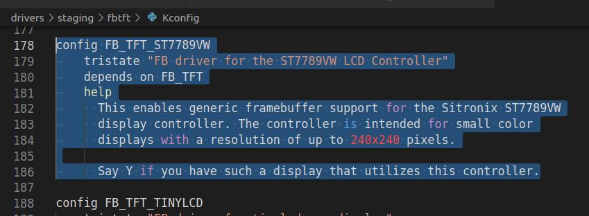
在Kconfig中添加
config FB_TFT_ST7789VW
	tristate "FB driver for the ST7789VW LCD Controller"
	depends on FB_TFT
	help
	  This enables generic framebuffer support for the Sitronix ST7789VW
	  display controller. The controller is intended for small color
	  displays with a resolution of up to 240x240 pixels.

	  Say Y if you have such a display that utilizes this controller.
编译
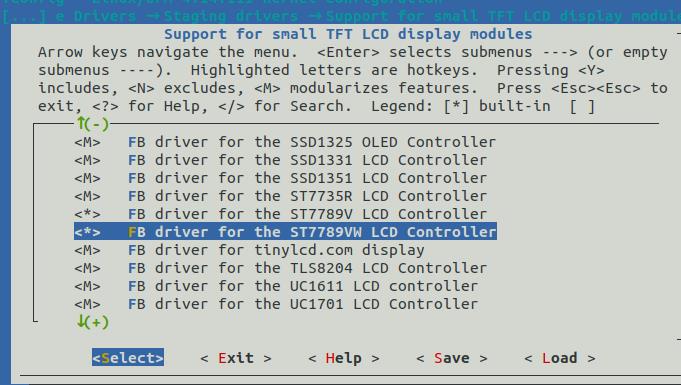
到menuconfig中使能此驱动
make menuconfig ARCH=arm CROSS_COMPILE=arm-linux-
Device Drivers  --->
	[*] Staging drivers  --->
		<*>   Support for small TFT LCD display modules  --->
			<*>   FB driver for the ST7789VW LCD Controller
# 编译内核、设备树
make zImage dtbs ARCH=arm CROSS_COMPILE=arm-linux-

# 网络更新内核
scp arch/arm/boot/zImage root@192.168.0.101:/boot

# 网络更新设备树
scp arch/arm/boot/dts/sun8i-h3-nanopi-neo-air.dtb root@192.168.0.101:/boot
实际效果
命令行
上面的步骤做完了,重启就会有如下画面
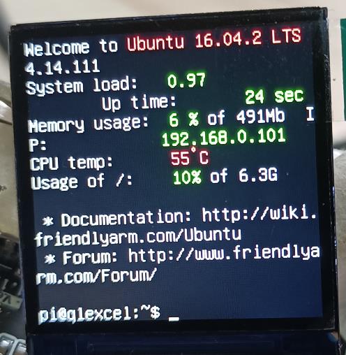
我们一直使用SecureCRT作为Linux开发板终端,开发板通过串口和SecureCRT进行通信。现在我们已经驱动起来 LCD 了,所以可以设置 LCD 作为终端,也就是开发板使用自己的显示设备作为自己的终端,然后接上键盘就可以直接在开发板上敲命令了。
我们就拥有了两套终端,一个是基于串口的 SecureCRT,一个就是我们开发板的 LCD屏幕,但是为了方便调试,我们以后还是以 SecureCRT 为主。我们可以通过下面这一行命令向LCD 屏幕输出“hello linux!”
echo hello linux > /dev/tty1
播放视频
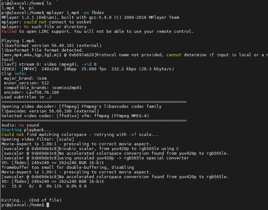
sudo apt install mplayer        # 安装mplayer
mplayer 1.mp4 -vo fbdev
运行QT
下面的指令都要切换root执行
apt-get update && apt-get install git
git clone https://github.com/friendlyarm/matrix.git
cd matrix/demo/nanopi-status
./build.sh
./run.sh /dev/fb_st7789vw
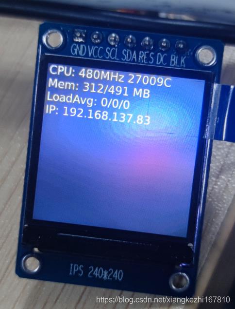
轻量级界面
sudo apt install xfce4
startx
让屏幕旋转180度
如果要让屏幕旋转180度,首先修改设备树:
&spi0
	/* needed to avoid dtc warning */
	#address-cells = <1>;
	#size-cells = <0>;

	status = "okay";
	pinctrl-names = "default";
	pinctrl-0 = <&spi0_pins &spi0_cs_pins>;
	cs-gpios = <&pio 2 3 GPIO_ACTIVE_HIGH>, <&pio 0 6 GPIO_ACTIVE_HIGH>; /*SPI-CS:PC3 and PA6*/

	pitft: pitft@0
		compatible = "sitronix,st7789vw";
		reg = <0>;
		status = "okay";

		spi-max-frequency = <50000000>;
		rotate = <180>;
		fps = <33>;
		buswidth = <8>;
		dc-gpios = <&pio 0 1 GPIO_ACTIVE_HIGH>;	 /* PA1 */
		reset-gpios = <&pio 6 11 GPIO_ACTIVE_HIGH>; /* PG11 */
		led-gpios = <&pio 0 0 GPIO_ACTIVE_LOW>;	 /* PA0 */
		debug = <0x0>;
	;
;
drivers/staging/fbtft/fb_st7789vw.c驱动中的set_var函数会生效,修改相应寄存器

如果这个时候直接测试,会发现屏幕有偏移,屏幕只有上部分有显示。
因此还需要修改下面函数来纠正:
static void set_addr_win(struct fbtft_par *par, int xs, int ys, int xe, int ye)

	switch(par->info->var.rotate)

		case   0: xs+=0;xe+=0;ys+=0;ye+=0;
				 break;
		// case  90: xs+=0;xe+=0;ys+=53;ye+=53;
		// 		 break;
		case 180: xs+=0;xe+=0;ys+=80;ye+=80;
				 break;
		// case 270: xs+=0;xe+=0;ys+=53;ye+=53;
		// 		 break;
		default :
				 break;


	write_reg(par, MIPI_DCS_SET_COLUMN_ADDRESS,
		  xs >> 8, xs & 0xFF, xe >> 8, xe & 0xFF);

	write_reg(par, MIPI_DCS_SET_PAGE_ADDRESS,
		  ys >> 8, ys & 0xFF, ye >> 8, ye & 0xFF);

	write_reg(par, MIPI_DCS_WRITE_MEMORY_START);
旋转90度和270度不知道需不需要纠偏,等以后用到再说。
以上是关于NanoPi NEO Air使用十二:使用自带的fbtft驱动点亮SPI接口TFT屏幕,ST7789V的主要内容,如果未能解决你的问题,请参考以下文章