合肥工业大学计组实验四
Posted 上衫_
tags:
篇首语:本文由小常识网(cha138.com)小编为大家整理,主要介绍了合肥工业大学计组实验四相关的知识,希望对你有一定的参考价值。
实验目的
通过设计并实现支持一条指令的CPU,理解和掌握CPU设计的基本原理和过程。
实验内容
设计和实现一个支持加法指令的单周期CPU。要求该加法指令(表示为add r1,r2,r3)格式约定如下:
采用寄存器寻址,r1,r2,r3为寄存器编号,r1和r2存放两个源操作数,r3为目标寄存器,其功能为[r1] + [r2] -> r3;
指令字长16位,操作码和地址码字段分配如下所示:

实验原理
1. 各个部件的功能及端口
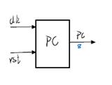
- PC
在每个时钟周期上沿对pc加一后输出,从而得到下一条要执行的指令。
端口:clk、rst、[7:0]pc
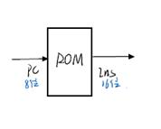
- ROM
输出要执行的指令。
端口:[7:0]pc、[15:0]ins
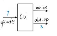
- CU
分析从ROM中取出的指令,从而控制ALU和寄存器堆RF的动作。
端口:[6:0]opcode、wr_en、[2:0]alu_op
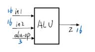
- ALU
根据指令的不同,完成不同的运算。
端口:[15:0]in1、[15:0]in2、[2:0]alu_op、[15:0]z
- RF
通用寄存器堆
端口:[2:0]read_reg1、[2:0]read_reg2、[2:0]write_reg、[15:0]write_data、clk、wr_en、[15:0]reg1、[15:0]reg2
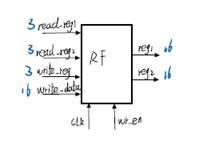
2. 数据通路连接
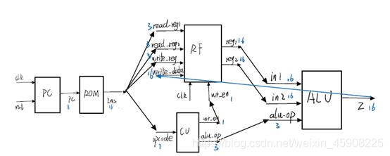
实验过程
1. 各个部件的设计
PC
1.	module PC(
2.	    input clk,
3.	    input rst,
4.	    output reg [7:0] pc
5.	    );
6.	    initial pc=8'd0;
7.	    always@(posedge clk) begin
8.	        begin
9.	        if(rst==1)
10.	            pc<=8'd0;
11.	        else
12.	            pc<=pc+1'd1;
13.	        end
14.	    end
15.	endmodule
ROM
1.	module ROM(
2.	    input wire [7:0] pc,
3.	    output reg [15:0] ins
4.	    );
5.
6.	    reg [15:0] ROM_data [255:0];
7.	    integer i;
8.
9.	    initial $readmemb("D:/vivadowork/ONE_CPU/ONE_CPU.srcs/sources_1/new/ROM_initial.txt",ROM_data);
10.
11.	    always@(pc) begin
12.	        ins<=ROM_data[pc];
13.	    end
14.	endmodule
CU
由于目前只需要实现一条指令,所以CU的设计比较简单,等后面设计多指令时再继续完善。
1.	module CU(
2.	    input wire [6:0] opcode,
3.	    output reg wr_en,
4.	    output reg [2:0] alu_op
5.	    );
6.	    always@(opcode)begin
7.	        wr_en<=1'd1;
8.	        alu_op<=3'd1;
9.	    end
10.
11.	endmodule
ALU
1.	module ALU(
2.	    input wire[15:0] in1,
3.	    input wire[15:0] in2,
4.	    input wire[2:0] alu_op,
5.	    output reg[15:0] z
6.	    );
7.	    always @(*)
8.	    begin
9.	    case(alu_op)
10.	    3'b001: z<=in1+in2;
11.	    3'b010: z<=in1-in2;
12.	    3'b011: z<=in1&in2;
13.	    3'b100: z<=in1|in2;
14.	    3'b101: z<=in1<<in2;
15.	    3'b110: z<=in1>>in2;
16.	    endcase
17.	    end
18.	endmodule
RF
1.	module RF(
2.	    input wire [2:0] read_reg1,
3.	    input wire [2:0] read_reg2,
4.	    input wire [15:0] write_data,
5.	    input wire [2:0] write_reg,
6.	    input wire wr_en,
7.	    input wire clk,
8.	    input wire rst,
9.	    output wire [15:0] reg1,
10.	    output wire [15:0] reg2
11.	    );
12.	    reg [15:0] rf [7:0];
13.
14.	    initial $readmemh ("D:/vivadowork/ONE_CPU/ONE_CPU.srcs/sources_1/new/RF_initial.txt",rf);
15.
16.	    integer i;
17.
18.	    always @(posedge clk  )
19.	    begin
20.	        begin
21.	        if(wr_en==1)
22.	            rf[write_reg]<=write_data;
23.	        end
24.	    end
25.	    assign reg1=rf[read_reg1];
26.	    assign reg2=rf[read_reg2];
27.	endmodule
2. 顶层文件封装实现
1.	module CPU(
2.	    input clk,
3.	    input rst,
4.	    output wire [7:0] pc,
5.	    output wire [15:0] ins,
6.	    output wire [2:0] alu_op,
7.	    output wr_en,
8.	    output wire [15:0] z,
9.	    output wire [15:0] reg1,
10.	    output wire [15:0] reg2
11.	    );
12.
13.
14.	    PC f_pc(
15.	        .clk(clk),
16.	        .rst(rst),
17.	        .pc(pc));
18.
19.	    ROM f_rom(
20.	        .pc(pc),
21.	        .ins(ins));
22.
23.	    CU f_cu(
24.	        .opcode(ins[15:9]),
25.	        .wr_en(wr_en),
26.	        .alu_op(alu_op)
27.	        );
28.
29.	    RF f_rf(
30.	        .read_reg1(ins[8:6]),
31.	        .read_reg2(ins[5:3]),
32.	        .write_reg(ins[2:0]),
33.	        .write_data(z),
34.	        .clk(clk),
35.	        .wr_en(wr_en),
36.	        .reg1(reg1),
37.	        .reg2(reg2)
38.	        );
39.
40.	    ALU f_alu(
41.	        .in1(reg1),
42.	        .in2(reg2),
43.	        .alu_op(alu_op),
44.	        .z(z)
45.	        );
46.	endmodule
3. CPU模拟仿真
1) 仿真说明
ROM初始化内容:
将以下两条命令重复128次。
0000001001010011
0000001100011010
命令解释:此次实验我将加法指令的设为0000001,后面指令的意思是将001b号寄存的内容与010b号寄存器的内容相加再将结果保存到011b号寄存器中;下一条指令同理,将100b号寄存器的内容与011b号寄存器的内容相加再将结果保存到010b号寄存器中。
RF初始化内容:
0001
0002
000A
0011
0015
0756
100F
0000
RF内容是以十六进制数据初始化的。
2) 仿真代码设计
每20ns为一个时钟周期,总共运行20个周期。
1.	module test_CPU;
2.	    reg clk;
3.	    reg rst;
4.	    wire [7:0] pc;
5.	    wire [15:0] ins;
6.	    wire wr_en;
7.	    wire [2:0] alu_op;
8.	    wire [15:0] reg1;
9.	    wire [15:0] reg2;
10.	    wire [15:0] z;
11.
12.	    initial begin
13.	        clk=1'd0;
14.	        forever #10 clk=~clk;
15.	    end
16.
17.	    initial begin
18.	        rst=1'd0;
19.	        #400 $stop;
20.	    end
21.
22.	    CPU test(
23.	        .clk(clk),
24.	        .rst(rst),
25.	        .z(z),
26.	        .pc(pc),
27.	        .ins(ins),
28.	        .wr_en(wr_en),
29.	        .alu_op(alu_op),
30.	        .reg1(reg1),
31.	        .reg2(reg2)
32.	        );
33.	endmodule
3) 仿真结果
reg1 + reg2 = z
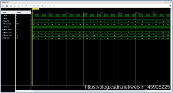
进一步实验
(一) 增加st指令
1. 分析
st指令

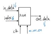
需要添加的部件:RAM
端口:[15:0]in_data、[5:0]index、clk、m_wr_en、[15:0]out_data
1.	module RAM(
2.	    input clk,
3.	    input m_wr_en,
4.	    input wire [15:0] in_data,
5.	    input wire [5:0] index,
6.	    output wire [15:0] out_data
7.	    );
8.
9.	    reg [15:0] initdata [1023:0];
10.	    integer i;
11.	    initial $readmemb("D:/vivadowork/ONE_CPU/ONE_CPU.srcs/sources_1/new/RAM_initial",initdata);
12.	//    initial begin
13.	//        for( i=0;i<1024;i=i+1)
14.	//            initdata[i]<=16'b0;
15.	//    end
16.
17.	    always@(posedge clk ) begin
18.	        begin if (m_wr_en==0)
19.	            initdata[index]<=in_data;
20.	        end
21.	    end
22.
23.	    assign out_data=initdata[index];
24.	endmodule
2. 更改顶层文件
数据通路更新
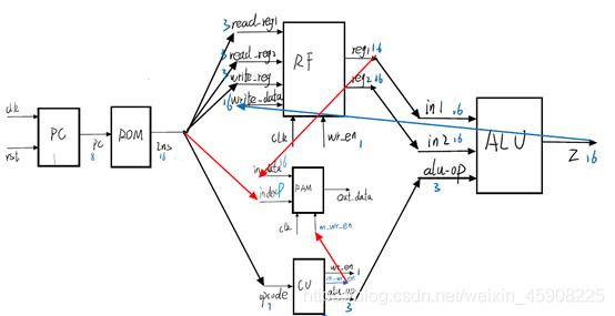
顶层文件更新
1.	module CPU(
2.	    input clk,
3.	    input rst,
4.	    output wire [7:0] pc,
5.	    output wire [15:0] ins,
6.	    output wire [2:0] alu_op,
7.	    output wr_en,
8.	    output m_wr_en,
9.	    output wire [15:0] z,
10.	    output wire [15:0] reg1,
11.	    output wire [15:0] reg2,
12.	    output wire [15:0] out_data
13.	    );
14.
15.
16.	    PC f_pc(
17.	        .clk(clk),
18.	        .rst(rst),
19.	        .pc(pc));
20.
21.	    ROM f_rom(
22.	        .pc(pc),
23.	        .ins(ins));
24.
25.	    RAM f_ram(
26.	        .clk(clk),
27.	        .m_wr_en(m_wr_en),
28.	        .in_data(reg1),
29.	        .index(ins[5:0]),
30.	        .out_data(out_data)
31.	        );
32.
33.	    CU f_cu(
34.	        .opcode(ins[15:9]),
35.	        .wr_en(wr_en),
36.	        .alu_op(alu_op),
37.	        .m_wr_en(m_wr_en) //
38.	        );
39.
40.	    RF f_rf(
41.	        .read_reg1(ins[8:6]),
42.	        .read_reg2(ins[5:3]),
43.	        .write_reg(ins[2:0]),
44.	        .write_data(z),
45.	        .clk(clk),
46.	        .wr_en(wr_en),
47.	        .reg1(reg1),
48.	        .reg2(reg2)
49.	        );
50.
51.	    ALU f_alu(
52.	        .in1(reg1),
53.	        .in2(reg2),
54.	        .alu_op(alu_op),
55.	        .z(z)
56.	        );
57.	endmodule
3. 模拟仿真
1) 仿真说明
RAM大小为1024
2) ROM初始化
0000010001000001 //0000010 表示为存数指令 001 表示要读取的寄存器 000001 表示要保存的RAM的地址
0000001011000001 //0000001 表示为加法命令
3) RAM初始化,将以下两条重复512次。
1010001111010100
0000110101110011
4) 仿真结果
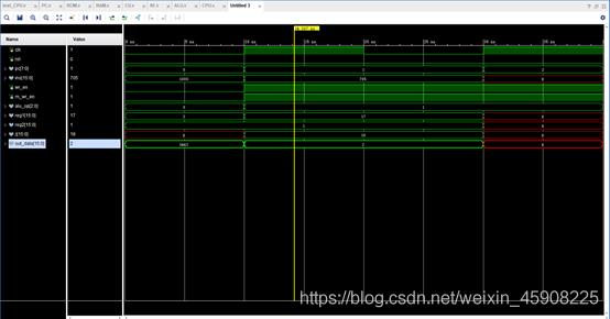
(二) 增加 加法 add、立即数加 addi、存数 st、取数 ld
1. 分析指令

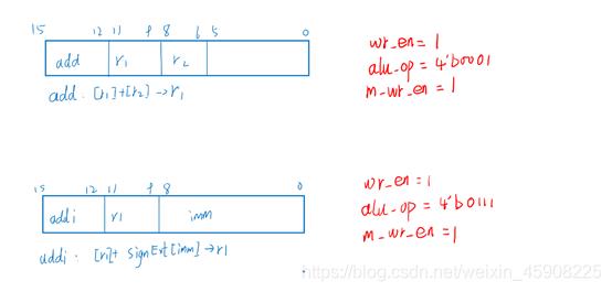
分析指令可知需要将更改控制器CU和运算器ALU的代码,现做更改如下:
CU:使用case语句分别对应四种指令,每种情况输出不同的wr_en alu_op m_wr_en以实现对应的功能。
ALU:之前ALU中的alu_op位数为3,现在增加了两种操作addi与ld,所以将alu_op位数改为4,同时增加两种运算:
①扩展立即数并与in1相加
②将从RAM中读出的out_data赋值给z,以便于将其写入RF。
1.	module CU(
2.	    input wire [3:0] opcode,
3.	    output reg wr_en,
4.	    output reg m_wr_en,
5.	    output reg [2:0] alu_op
6.	    );
7.	    always@(opcode)begin
8.	        case(opcode)
9.	        4'b0001: begin //add
10.	            wr_en<=1'd1;
11.	            alu_op<=3'b001;
12.	            m_wr_en<=1'd1;
13.	        end
14.	        4'b0010: begin //addi
15.	            wr_en<=1'd1;
16.	            alu_op<=3'b111;
17.	            m_wr_en<=1'd1;
18.	        end
19.	        4'b0011: begin //st
20.	            wr_en<=1'd0;
21.	            alu_op<=3'd0;
22.	            m_wr_en<=1'd0;
23.	        end
24.	        4'b0100: begin //lod
25.	            wr_en=1'b1;
26.	            alu_op<=3'd0;
27.	            m_wr_en<=1'd1;
28.	        end
29.	        endcase
30.	    end
31.	endmodule
进一步更改alu文件,由于addi指令需要进行符号为扩展,所以在ALU中增加相应的功能;ld指令要将RAM中读取到的数据保存到RF中,
1. module ALU(
2. input wire[15:0] in1,
3. input wire[15:0] in2,
4. input wire[8:0] imm,
5. input wire[3:0] alu_op,
6. input wire[15:0] out_data,
7. output reg[15:0] z
8. );
9. always @(*)
10. begin
11. case(alu_op)
12. 4'b0001: z<=in1+in2;
13. 4'b0010: z<=in1-in2;
14. 4'b0011: z<=in1&in2;
15. 4'b0100: z<=in1|in2;
16. 4'b0101: z<=in1<<in2;
17. 4'b0110: z<=in1>>in2;
18. 4'b0111: z<=6imm[8],imm+in1;
19. 4'b1000: z<=out_data;
20. endcase
21. end
22. endmodule
最后修改顶层文件,增加alu的输入内容。
1. module CPU(
2. input clk,
3. input rst,
4. output wire [7:0] pc,
5. output wire [15:0] ins,
6. output wire [3:0] alu_op,
7. output wr_en,
8. output m_wr_en,
9. output wire [15:0] z,
10. output wire [15:0] reg1,
11. output wire [15:0] reg2,
12. output wire [15:0] out_data
13. );
14.
15.
16. PC f_pc(
17. .clk(clk),
18. .rst(rst),
19. .pc