视觉高级篇25 # 如何用法线贴图模拟真实物体表面
Posted 凯小默
tags:
篇首语:本文由小常识网(cha138.com)小编为大家整理,主要介绍了视觉高级篇25 # 如何用法线贴图模拟真实物体表面相关的知识,希望对你有一定的参考价值。
说明
【跟月影学可视化】学习笔记。
什么是法线贴图?
法线贴图就是在原物体的凹凸表面的每个点上均作法线,通过RGB颜色通道来标记法线的方向,你可以把它理解成与原凹凸表面平行的另一个不同的表面,但实际上它又只是一个光滑的平面。对于视觉效果而言,它的效率比原有的凹凸表面更高,若在特定位置上应用光源,可以让细节程度较低的表面生成高细节程度的精确光照方向和反射效果。
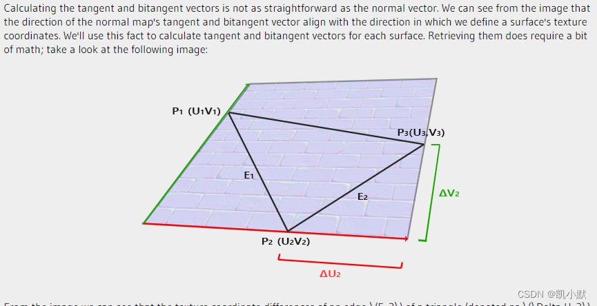
什么是切线空间?
切线空间(Tangent Space)是一个特殊的坐标系,它是由几何体顶点所在平面的 uv 坐标和法线构成的。
切线空间的三个轴,一般用 T (Tangent)、B (Bitangent)、N (Normal) 三个字母表示,所以切线空间也被称为 TBN 空间。其中 T 表示切线、B 表示副切线、N 表示法线。

为什么需要切线空间?
法线是垂直于面的单位向量,当在贴图中记录法线时,其坐标系有如下选择:
世界坐标系:当面改变朝向改变时,贴图中的法线就失效了模型坐标系:需要根据面的朝向,生成不同的法线贴图。想象一个立方体的砖头,他们的6个面的法线情况是一样的,也需要根据面的不同朝向生成对应的法线贴图
切线空间就是为了解决法线贴图的问题的。为了能统一使用一张法线贴图,就引出了切线空间。
切线空间中的 TBN 是怎么计算的?
数学推导过程比较复杂,有兴趣的可以看一下这篇法线贴图的文章:Normal Mapping
公式如下:
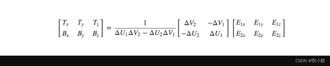
通过 UV 坐标和点 P1、P2、P3 的坐标求出对应的 T 和 B 坐标:
function createTB(geometry)
  const position, index, uv = geometry.attributes;
  if(!uv) throw new Error('NO uv.');
  function getTBNTriangle(p1, p2, p3, uv1, uv2, uv3)
    const edge1 = new Vec3().sub(p2, p1);
    const edge2 = new Vec3().sub(p3, p1);
    const deltaUV1 = new Vec2().sub(uv2, uv1);
    const deltaUV2 = new Vec2().sub(uv3, uv1);

    const tang = new Vec3();
    const bitang = new Vec3();

    const f = 1.0 / (deltaUV1.x * deltaUV2.y - deltaUV2.x * deltaUV1.y);

    tang.x = f * (deltaUV2.y * edge1.x - deltaUV1.y * edge2.x);
    tang.y = f * (deltaUV2.y * edge1.y - deltaUV1.y * edge2.y);
    tang.z = f * (deltaUV2.y * edge1.z - deltaUV1.y * edge2.z);

    tang.normalize();

    bitang.x = f * (-deltaUV2.x * edge1.x + deltaUV1.x * edge2.x);
    bitang.y = f * (-deltaUV2.x * edge1.y + deltaUV1.x * edge2.y);
    bitang.z = f * (-deltaUV2.x * edge1.z + deltaUV1.x * edge2.z);

    bitang.normalize();

    return tang, bitang;


  const size = position.size;
  if(size < 3) throw new Error('Error dimension.');

  const len = position.data.length / size;
  const tang = new Float32Array(len * 3);
  const bitang = new Float32Array(len * 3);

  for(let i = 0; i < index.data.length; i += 3)
    const i1 = index.data[i];
    const i2 = index.data[i + 1];
    const i3 = index.data[i + 2];

    const p1 = [position.data[i1 * size], position.data[i1 * size + 1], position.data[i1 * size + 2]];
    const p2 = [position.data[i2 * size], position.data[i2 * size + 1], position.data[i2 * size + 2]];
    const p3 = [position.data[i3 * size], position.data[i3 * size + 1], position.data[i3 * size + 2]];

    const u1 = [uv.data[i1 * 2], uv.data[i1 * 2 + 1]];
    const u2 = [uv.data[i2 * 2], uv.data[i2 * 2 + 1]];
    const u3 = [uv.data[i3 * 2], uv.data[i3 * 2 + 1]];

    const tang: t, bitang: b = getTBNTriangle(p1, p2, p3, u1, u2, u3);
    tang.set(t, i1 * 3);
    tang.set(t, i2 * 3);
    tang.set(t, i3 * 3);
    bitang.set(b, i1 * 3);
    bitang.set(b, i2 * 3);
    bitang.set(b, i3 * 3);

  geometry.addAttribute('tang', data: tang, size: 3);
  geometry.addAttribute('bitang', data: bitang, size: 3);
  return geometry;
构建 TBN 矩阵来计算法向量
TBN 矩阵的作用,就是将法线贴图里面读取的法向量数据,转换为对应的切线空间中实际的法向量。
顶点着色器增加了 tang 和 bitang 这两个属性,这里使用 WebGL2.0 的写法,它对应是 OpenGL ES3.0。
里面用 in 和 out 对应变量的输入和输出,来取代 OpenGL ES2.0 的 attribute 和 varying。
顶点着色器:
#version 300 es
precision highp float;

in vec3 position;
in vec3 normal;
in vec2 uv;
in vec3 tang;
in vec3 bitang;

uniform mat4 modelMatrix;
uniform mat4 modelViewMatrix;
uniform mat4 viewMatrix;
uniform mat4 projectionMatrix;
uniform mat3 normalMatrix;
uniform vec3 cameraPosition;

out vec3 vNormal;
out vec3 vPos;
out vec2 vUv;
out vec3 vCameraPos;
out mat3 vTBN;

void main()
  vec4 pos = modelViewMatrix * vec4(position, 1.0);
  vPos = pos.xyz;
  vUv = uv;
  vCameraPos = (viewMatrix * vec4(cameraPosition, 1.0)).xyz;
  vNormal = normalize(normalMatrix * normal);

  vec3 N = vNormal;
  vec3 T = normalize(normalMatrix * tang);
  vec3 B = normalize(normalMatrix * bitang);

  vTBN = mat3(T, B, N);

  gl_Position = projectionMatrix * pos;
片元着色器:
#version 300 es
precision highp float;

#define MAX_LIGHT_COUNT 16
uniform mat4 viewMatrix;

uniform vec3 ambientLight;
uniform vec3 directionalLightDirection[MAX_LIGHT_COUNT];
uniform vec3 directionalLightColor[MAX_LIGHT_COUNT];
uniform vec3 pointLightColor[MAX_LIGHT_COUNT];
uniform vec3 pointLightPosition[MAX_LIGHT_COUNT];
uniform vec3 pointLightDecay[MAX_LIGHT_COUNT];
uniform vec3 spotLightColor[MAX_LIGHT_COUNT];
uniform vec3 spotLightDirection[MAX_LIGHT_COUNT];
uniform vec3 spotLightPosition[MAX_LIGHT_COUNT];
uniform vec3 spotLightDecay[MAX_LIGHT_COUNT];
uniform float spotLightAngle[MAX_LIGHT_COUNT];

uniform vec3 materialReflection;
uniform float shininess;
uniform float specularFactor;

uniform sampler2D tNormal;

in vec3 vNormal;
in vec3 vPos;
in vec2 vUv;
in vec3 vCameraPos;
in mat3 vTBN;

out vec4 FragColor;

float getSpecular(vec3 dir, vec3 normal, vec3 eye)
  vec3 reflectionLight = reflect(-dir, normal);
  float eyeCos = max(dot(eye, reflectionLight), 0.0);
  return specularFactor *  pow(eyeCos, shininess);


vec4 phongReflection(vec3 pos, vec3 normal, vec3 eye)
  float specular = 0.0;
  vec3 diffuse = vec3(0);

  // 处理平行光
  for(int i = 0; i < MAX_LIGHT_COUNT; i++)
    vec3 dir = directionalLightDirection[i];
    if(dir.x == 0.0 && dir.y == 0.0 && dir.z == 0.0) continue;
    vec4 d = viewMatrix * vec4(dir, 0.0);
    dir = normalize(-d.xyz);
    float cos = max(dot(dir, normal), 0.0);
    diffuse += cos * directionalLightColor[i];
    specular += getSpecular(dir, normal, eye);


  // 处理点光源
  for(int i = 0; i < MAX_LIGHT_COUNT; i++)
    vec3 decay = pointLightDecay[i];
    if(decay.x == 0.0 && decay.y == 0.0 && decay.z == 0.0) continue;
    vec3 dir = (viewMatrix * vec4(pointLightPosition[i], 1.0)).xyz - pos;
    float dis = length(dir);
    dir = normalize(dir);
    float cos = max(dot(dir, normal), 0.0);
    float d = min(1.0, 1.0 / (decay.x * pow(dis, 2.0) + decay.y * dis + decay.z));
    diffuse += d * cos * pointLightColor[i];
    specular += getSpecular(dir, normal, eye);


  // 处理聚光灯
  for(int i = 0; i < MAX_LIGHT_COUNT; i++)
    vec3 decay = spotLightDecay[i];
    if(decay.x == 0.0 && decay.y == 0.0 && decay.z == 0.0) continue;

    vec3 dir = (viewMatrix * vec4(spotLightPosition[i], 1.0)).xyz - pos;
    float dis = length(dir);
    dir = normalize(dir);

    // 聚光灯的朝向
    vec3 spotDir = (viewMatrix * vec4(spotLightDirection[i], 0.0)).xyz;
    // 通过余弦值判断夹角范围
    float ang = cos(spotLightAngle[i]);
    float r = step(ang, dot(dir, normalize(-spotDir)));

    float cos = max(dot(dir, normal), 0.0);
    float d = min(1.0, 1.0 / (decay.x * pow(dis, 2.0) + decay.y * dis + decay.z));
    diffuse += r * d * cos * spotLightColor[i];
    specular += r * getSpecular(dir, normal, eye);


  return vec4(diffuse, specular);


vec3 getNormal()
  vec3 n = texture(tNormal, vUv).rgb * 2.0 - 1.0;
  return normalize(vTBN * n);


void main()
  vec3 eyeDirection = normalize(vCameraPos - vPos);
  vec3 normal = getNormal();
  vec4 phong = phongReflection(vPos, normal, eyeDirection);

  // 合成颜色
  FragColor.rgb = phong.w + (phong.xyz + ambientLight) * materialReflection;
  FragColor.a = 1.0;
通过顶点数据计算几何体的切线和副切线,然后得到 TBN 矩阵,用 TBN 矩阵和法线纹理数据来计算法向量,从而完成法线贴图。
注意:着色器里需要加 #version 300 es ,不然会报错,它表示这段代码是 OpenGL ES3.0 的。
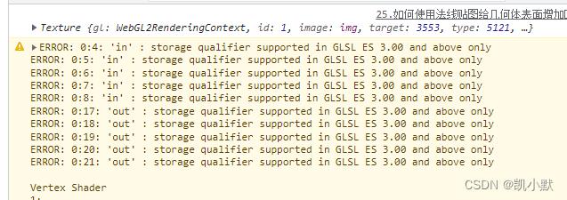
可以参考这篇:glsl version 300es 关键字
使用偏导数来实现法线贴图
用顶点数据计算几何体的切线和副切线相对来说是复杂了一点,还可以使用坐标插值和法线纹理来计算。
具体如下:其中 dFdx、dFdy 是 GLSL 内置函数,可以求插值的属性在 x、y 轴上的偏导数。
vec3 getNormal()
	vec3 pos_dx = dFdx(vPos.xyz);
	vec3 pos_dy = dFdy(vPos.xyz);
	vec2 tex_dx = dFdx(vUv);
	vec2 tex_dy = dFdy(vUv);

	vec3 t = normalize(pos_dx * tex_dy.t - pos_dy * tex_dx.t);
	vec3 b = normalize(-pos_dx * tex_dy.s + pos_dy * tex_dx.s);
	mat3 tbn = mat3(t, b, normalize(vNormal));

	vec3 n = texture(tNormal, vUv).rgb * 2.0 - 1.0;
	return normalize(tbn * n);
偏导数代表插值的属性向量在 x、y 轴上的变化率,或者说曲面的切线。再将顶点坐标曲面切线与 uv 坐标的切线求叉积,就能得到垂直于两条切线的法线。对应 TBN 空间的切线 tang 和副切线 bitang。然后使用偏导数构建 TBN 矩阵,把 TBN 矩阵左乘从法线纹理中提取出的值,就可以计算出对应的法向量。不过计算偏导数也有一定的性能开销。
如何使用法线贴图给几何体表面增加凹凸效果?
下面我们准备这个图当纹理,实现一个正方体的法线贴图:

代码如下:这里使用的是偏导数来实现的
<!DOCTYPE html>
<html lang="en">
    <head>
        <meta charset="UTF-8" />
        <meta http-equiv="X-UA-Compatible" content="IE=edge" />
        <meta name="viewport" content="width=device-width, initial-scale=1.0" />
        <title>如何使用法线贴图给几何体表面增加凹凸效果</title>
        <style>
            canvas
                border: 1px dashed #fa8072;

        </style>
    </head>
    <body>
        <canvas width="512" height="512"></canvas>
        <script type="module">
            import  Renderer, Camera, Transform, Box, Orbit, Program, Texture, Mesh, Color, Vec3, Vec2  from './common/lib/ogl/index.mjs';
            import  Phong, Material  from './common/lib/phong.js';

            const vertex = `#version 300 es
                precision highp float;

                in vec3 position;
                in vec3 normal;
                in vec2 uv;
                in vec3 tang;
                in vec3 bitang;

                uniform mat4 modelMatrix;
                uniform mat4 modelViewMatrix;
                uniform mat4 viewMatrix;
                uniform mat4 projectionMatrix;
                uniform mat3 normalMatrix;
                uniform vec3 cameraPosition;

                out vec3 vNormal;
                out vec3 vPos;
                out vec2 vUv;
                out vec3 vCameraPos;
                out mat3 vTBN;

                void main()
                    vec4 pos = modelViewMatrix * vec4(position, 1.0);
                    vPos = pos.xyz;
                    vUv = uv;
                    vCameraPos = (viewMatrix * vec4(cameraPosition, 1.0)).xyz;
                    vNormal = normalize(normalMatrix * normal);

                    vec3 N = vNormal;
                    vec3 T = normalize(normalMatrix * tang);
                    vec3 B = normalize(normalMatrix * bitang);

                    vTBN = mat3(T, B, N);

                    gl_Position = projectionMatrix * pos;

            `;

            const fragment = `#version 300 es
                precision highp float;

                #define MAX_LIGHT_COUNT 16
                uniform mat4 viewMatrix;

                uniform vec3 ambientLight;
                uniform vec3 directionalLightDirection[MAX_LIGHT_COUNT];
                uniform vec3 directionalLightColor[MAX_LIGHT_COUNT];
                uniform vec3 pointLightColor[MAX_LIGHT_COUNT];
                uniform vec3 pointLightPosition[MAX_LIGHT_COUNT];
                uniform vec3 pointLightDecay[MAX_LIGHT_COUNT];
                uniform vec3 spotLightColor[MAX_LIGHT_COUNT];
                uniform vec3 spotLightDirection[MAX_LIGHT_COUNT];
                uniform vec3 spotLightPosition[MAX_LIGHT_COUNT];
                uniform vec3 spotLightDecay[MAX_LIGHT_COUNT];
                uniform float spotLightAngle[MAX_LIGHT_COUNT];

                uniform vec3 materialReflection;
                uniform float shininess;
             以上是关于视觉高级篇25 # 如何用法线贴图模拟真实物体表面的主要内容,如果未能解决你的问题,请参考以下文章