ESP32 UART串口通信
Posted Wireless_Link
tags:
篇首语:本文由小常识网(cha138.com)小编为大家整理,主要介绍了ESP32 UART串口通信相关的知识,希望对你有一定的参考价值。
零. 声明
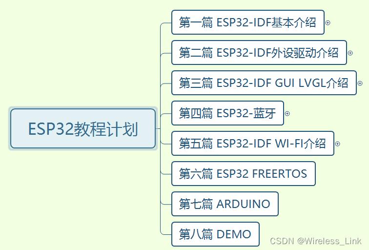
本专栏文章我们会以连载的方式持续更新,本专栏计划更新内容如下:

第一篇:ESP-IDF基本介绍,主要会涉及模组,芯片,开发板的介绍,环境搭建,程序编译下载,启动流程等一些基本的操作,让你对ESP-IDF开发有一个总体的认识,比我们后续学习打下基础!
第二篇:ESP32-IDF外设驱动介绍,主要会根据esp-idf现有的driver,提供各个外设的驱动,比如LED,OLED,SPI LCD,TOUCH,红外,Codec ic等等,在这一篇中,我们不仅仅来做外设驱动,还会对常用的外设总线做一个介绍,让大家知其然又知其所以然!
第三篇:目前比较火热的GUI LVGL介绍,主要会设计LVGL7.1,LVGL8的移植介绍,并且也会介绍各个组件,知道原理后,最后,我们会推出一款组态软件来构建我们的GUI,来提升我们的效率!
第四篇:ESP32-蓝牙,熟悉我的,应该都知道,我即使从事蓝牙协议栈的开发的,所以这个是我们独有的优势,在这一篇章,我们会提供不仅仅是蓝牙应用方法的知识,也会应用结合蓝牙底层协议栈的理论,让你彻底从上到下打通蓝牙任督二脉!
第五篇:Wi-Fi介绍,熟悉我的,应该也知道,我们也做过一款sdio wifi的驱动教程板子,所以在wifi这方面我们也是有独有的优势,在这一篇章,我们同样不仅仅提供Wi-Fi应用方面的知识,也会结合底层理论,让你对Wi-Fi有一个清晰的认知!
第六篇:FreeRTOS介绍,主要介绍下FreeRTOS各个功能(任务管理/消息队列/信号量/互斥量/事件/软件定时器/任务通知/内存管理/中断管理等)的使用以及运作机制。
第七篇:Arduino介绍,主要介绍ESP32 Arduino的基本操作(环境搭建,烧录,下载等开发流程),以及介绍下基于Arduino的外设,蓝牙,wifi的使用。
第八篇:Demo,此篇章是融会贯通以上章节,做一些综合性的demo,让你巩固以上篇章的同时,还能学到实际项目!!
另外,我们的教程包括但是不局限于以上篇章,为了给你一个更好的导航,以下信息尤其重要,请详细查看!!
------------------------------------------------------------------------------------------------------------------------------------------
蓝牙交流扣扣群:539357317
微信公众号↓↓↓↓↓↓↓↓↓↓↓↓↓↓↓↓↓↓↓↓↓↓↓↓↓↓↓↓↓↓↓↓↓↓↓↓↓↓↓↓↓↓↓↓↓↓↓↓↓↓↓↓↓↓↓↓↓↓↓↓↓↓↓↓↓↓↓↓↓↓↓↓↓↓↓

------------------------------------------------------------------------------------------------------------------------------------------
一、概述
通用异步收发送器(UART)是一种硬件特性,它使用广泛适应的异步串行通信接口(如RS 232、RS 422、RS 485)来处理通信(即时序要求和数据帧)。UART提供了一种广泛采用和廉价的方法来实现不同设备之间的全双工或半双工数据交换。
ESP32芯片有三个UART控制器(UART 0、UART 1和UART 2),它们具有一组相同的寄存器,以便于编程和灵活性。
每个UART控制器都是独立配置的,参数包括波特率、数据比特长度、位序、停止位数、奇偶校验位等。所有控制器都与不同厂商的UART支持设备兼容,还可以支持红外数据关联协议(IRDA)。
二.开发步骤
介绍如何使用UART驱动程序的功能和数据类型建立ESP32与其他UART设备之间的通信。概述反映了一个典型的编程工作流程,并被分成以下几个部分:
1)设置UART通信参数(波特率,数据位,停止位,奇偶检验,流控等)
2)设置UART通信PIN脚
3)驱动安装,用于申请ESP32资源用于UART通信
4)进行UART通信,接收发送数据
5)使用中断,触发通信各个EVENT
6)删除驱动,用于释放ESP32的UART驱动的资源
步骤1到3包括配置阶段。步骤4是UART开始运行的地方。步骤5和步骤6是可选的。
下面我们就一一介绍下这些步骤:
1.设置UART通信参数
1.1 使用一个函数来设置uart参数
使用函数 uart_param_config() 并且传递 uart_config_t结构体参数. uart_config_t结构体定义如下:
typedef struct
    int baud_rate;                      /*!< UART baud rate*/
    uart_word_length_t data_bits;       /*!< UART byte size*/
    uart_parity_t parity;               /*!< UART parity mode*/
    uart_stop_bits_t stop_bits;         /*!< UART stop bits*/
    uart_hw_flowcontrol_t flow_ctrl;    /*!< UART HW flow control mode (cts/rts)*/
    uint8_t rx_flow_ctrl_thresh;        /*!< UART HW RTS threshold*/
    union
        uart_sclk_t source_clk;         /*!< UART source clock selection */
        bool use_ref_tick  __attribute__((deprecated)); /*!< Deprecated method to select ref tick clock source, set source_clk field instead */
    ;
 uart_config_t;
例子:
const uart_port_t uart_num = UART_NUM_2;
uart_config_t uart_config =
    .baud_rate = 115200,
    .data_bits = UART_DATA_8_BITS,
    .parity = UART_PARITY_DISABLE,
    .stop_bits = UART_STOP_BITS_1,
    .flow_ctrl = UART_HW_FLOWCTRL_CTS_RTS,
    .rx_flow_ctrl_thresh = 122,
;
// Configure UART parameters
ESP_ERROR_CHECK(uart_param_config(uart_num, &uart_config));
1.2 使用多个函数来设置uart参数
| Parameter to Configure | Function |
| Baud rate | uart_set_baudrate() |
| Number of transmitted bits | uart_set_word_length() selected out of uart_word_length_t |
| Parity control | uart_set_parity() selected out of uart_parity_t |
| Number of stop bits | uart_set_stop_bits() selected out of uart_stop_bits_t |
| Hardware flow control mode | uart_set_hw_flow_ctrl() selected out of uart_hw_flowcontrol_t |
| Communication mode | uart_set_mode() selected out of uart_mode_t |
2.设置UART通信PIN脚
ESP32的串口是支持引脚映射的,比如我的开发板串口一默认的是GPIO9和GPIO10,现在将TX、RX映射到GPIO4和GPIO5上。
请调用函数uart_set_pin()并指定驱动程序应将Tx,Rx,RTS和CTS信号路由至的GPIO引脚号。
如果要为特定信号保留当前分配的管脚号,请传递宏UART_PIN_NO_CHANGE。应该为不使用的引脚指定相同的宏。
// Set UART pins(TX: IO4, RX: IO5, RTS: IO18, CTS: IO19)
ESP_ERROR_CHECK(uart_set_pin(UART_NUM_2, 4, 5, 18, 19));
3.驱动安装,用于申请ESP32资源用于UART通信
设置好通信引脚后,通过调用安装驱动程序uart_driver_install()并指定以下参数:
- Tx环形缓冲区的大小
- Rx环形缓冲区的大小
- 事件队列句柄和大小
- 分配中断的标志
该功能将为UART驱动程序分配所需的内部资源。
// Setup UART buffered IO with event queue
const int uart_buffer_size = (1024 * 2);
QueueHandle_t uart_queue;
// Install UART driver using an event queue here
ESP_ERROR_CHECK(uart_driver_install(UART_NUM_2, uart_buffer_size, \\
                                        uart_buffer_size, 10, &uart_queue, 0));
4.进行UART通信,接收发送数据
串行通信由每个UART控制器的有限状态机(FSM)控制。
发送数据的过程涉及以下步骤:
1)将数据写入Tx FIFO缓冲区
2)FSM序列化数据
3)FSM将数据发送出去
接收数据的过程类似,但是步骤相反:
1)FSM处理传入的串行流并将其并行化
2)FSM将数据写入Rx FIFO缓冲区
3)从Rx FIFO缓冲区读取数据
因此,应用程序将被限制为分别使用uart_write_bytes()和从相应的缓冲区写入和读取数据uart_read_bytes(),而FSM将完成其余的工作。
4.1 发送
准备好要传输的数据后,调用该函数uart_write_bytes()并将数据缓冲区的地址和数据长度传递给该函数。该函数将数据复制到Tx环形缓冲区(立即或在有足够空间可用之后),然后退出。当Tx FIFO缓冲区中有可用空间时,中断服务程序(ISR)将数据从Tx环形缓冲区移至后台的Tx FIFO缓冲区。下面的代码演示了此功能的用法。
// Write data to UART.
char* test_str = "This is a test string.\\n";
uart_write_bytes(uart_num, (const char*)test_str, strlen(test_str));该功能uart_write_bytes_with_break()类似于uart_write_bytes()但在传输结束时添加了一个串行中断信号。意味着它会在发送完数据之后,设置TX低电平一段时间(RTOS任务节拍为单位)。
// Write data to UART, end with a break signal.
uart_write_bytes_with_break(uart_num, "test break\\n",strlen("test break\\n"), 100);
将数据写入Tx FIFO缓冲区的另一个功能是uart_tx_chars()。不像uart_write_bytes(),此功能在可用空间之前不会阻塞。相反,它将写入可立即放入硬件Tx FIFO中的所有数据,然后返回已写入的字节数。
有一个“陪伴”功能uart_wait_tx_done(),可监视Tx FIFO缓冲区的状态并在其为空时返回。
// Wait for packet to be sent
const uart_port_t uart_num = UART_NUM_2;
ESP_ERROR_CHECK(uart_wait_tx_done(uart_num, 100)); // wait timeout is 100 RTOS ticks (TickType_t)
4.2 接收
UART接收到数据并将其保存在Rx FIFO缓冲区后,需要使用函数进行读出uart_read_bytes()。,这个函数会阻塞待在那里,直到读满需要的字节,或是超时。
在读取数据之前,您可以调用来检查Rx FIFO缓冲区中可用的字节数uart_get_buffered_data_len(),然后再读取相应的内容,这样就不会造成不必要的阻塞。下面给出了使用这些功能的示例。
// Read data from UART.
const uart_port_t uart_num = UART_NUM_2;
uint8_t data[128];
int length = 0;
ESP_ERROR_CHECK(uart_get_buffered_data_len(uart_num, (size_t*)&length));
length = uart_read_bytes(uart_num, data, length, 100);
如果不再需要Rx FIFO缓冲区中的数据,则可以通过调用清除缓冲区uart_flush()。
三.UART案例
我们通过几个案例来分别介绍下uart的用途
1.UART console
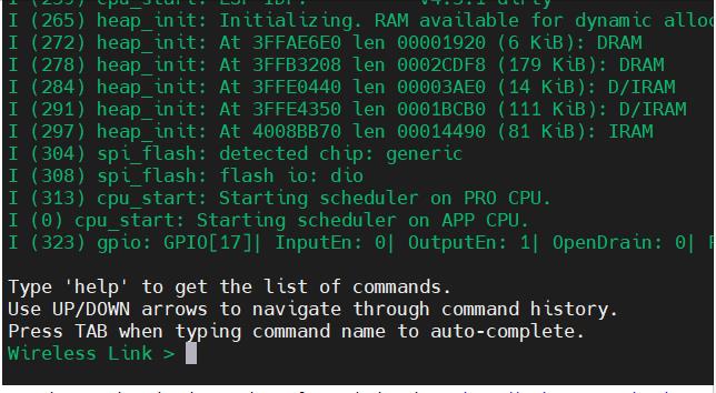
这个就类似于linux命令行模式,在Terminal敲命令,然后程序解析执行相应的动作!
主要分为以下几个步骤:
1)初始化 REPL 环境
在一个典型的 console 应用中,你只需要调用 esp_console_new_repl_uart(),它会为你初始化好构建在 UART 基础上的 REPL 环境,其中包括安装 UART 驱动,基本的 console 配置,创建一个新的线程来执行 REPL 任务,注册一些基本的命令
esp_console_repl_t *repl = NULL;
esp_console_repl_config_t repl_config = ESP_CONSOLE_REPL_CONFIG_DEFAULT();
esp_console_dev_uart_config_t uart_config = ESP_CONSOLE_DEV_UART_CONFIG_DEFAULT();
repl_config.prompt = "Wireless Link >";

ESP_ERROR_CHECK(esp_console_new_repl_uart(&uart_config, &repl_config, &repl));
2)注册命令
typedef struct
    /**
     * Command name. Must not be NULL, must not contain spaces.
     * The pointer must be valid until the call to esp_console_deinit.
     */
    const char *command;
    /**
     * Help text for the command, shown by help command.
     * If set, the pointer must be valid until the call to esp_console_deinit.
     * If not set, the command will not be listed in 'help' output.
     */
    const char *help;
    /**
     * Hint text, usually lists possible arguments.
     * If set to NULL, and 'argtable' field is non-NULL, hint will be generated
     * automatically
     */
    const char *hint;
    /**
     * Pointer to a function which implements the command.
     */
    esp_console_cmd_func_t func;
    /**
     * Array or structure of pointers to arg_xxx structures, may be NULL.
     * Used to generate hint text if 'hint' is set to NULL.
     * Array/structure which this field points to must end with an arg_end.
     * Only used for the duration of esp_console_cmd_register call.
     */
    void *argtable;
 esp_console_cmd_t;
ESP_ERROR_CHECK(esp_console_cmd_register(&console_cmd));
其中会注册cmd的字符串,以及cmd解析的callback
3)开始repl
ESP_ERROR_CHECK(esp_console_start_repl(repl));整个程序在github:esp32_study/2_peripheral/2_uart_console at main · sj15712795029/esp32_study · GitHub
效果如下:

敲help会出来你注册的所有的cmd,然后敲对应的command,会在callback中去解析对应的函数功能!
2.UART select
vfs具体用法请参照ESP32官网连接:
虚拟文件系统组件 - ESP32 - — ESP-IDF 编程指南 v4.4.1 文档
ESP32的uart可以同构vfs像Linux select函数来实现监测读,整个select的使用原理是:
select系统调用时用来让我们的程序监视多个文件句柄的状态变化的。程序会停在select这里等待,直到被监视的文件句柄有一个或多个发生了状态改变。
2.1函数原形
int select (int nfds, fd_set *readfds, fd_set *writefds, fd_set *exceptfds, struct timeval *timeout)
1)nfds: 所传入的最大文件描述符+1。所有加入集合的句柄值的最大那个那个值还要加1.比如我们创建了3个句柄。
在使用select函数之前,一定要找到3个句柄中的最大值是哪个,我们一般定义一个变量来保存最大值,取得最大socket值如下。
时间的结构体为:
struct timeval
    long tv_sec;   /*秒 */
    long tv_usec;  /*微秒 */
timeval 的值有三种情况:
- imeout == NULL :等待无限长的时间。等待可以被一个信号中断。当有一个描述符做好准备或者是捕获到一个信号时函数会返回。如果捕获到一个信号, select函数将返回 -1,并将变量 erro设为 EINTR。
- timeout->tv_sec = 0 且timeout->tv_usec = 0:不等待,直接返回。加入描述符集的描述符都会被测试,并且返回满足要求的描述符的个数。这种方法通过轮询,无阻塞地获得了多个文件描述符状态。
- timeout->tv_sec !=0或timeout->tv_usec!= 0: 等待指定的时间。当有描述符符合条件或者超过超时时间的话,函数返回。在超时时间即将用完但又没有描述符合条件的话,返回 0。对于第一种情况,等待也会被信号所中断。
(2) readfds、writefds、exceptset:分别指向可读、可写和异常等事件对应的描述符集合。其中,exceptset是特殊情况,即句柄上有特殊情况发生时系统会告诉select函数返回。特殊情况比如对方通过一个socket句柄发来了紧急数据,可用于处理带外数据。
数据结构fd_set实际上是一long类型的数组,每一个数组元素都能与一打开的文件句柄 (不管是socket句柄,还是其他文件或命名管道或设备句柄) 建立联系,建立联系的工作由程序员完成,当调用select()时,由内核根据IO状态修改fe_set的内容,由此来通知执行了select()的进程哪一socket或文件可读。
fd_set的操作可通过如下宏完成:
- FD_ZERO(&set): //将fd清零
- FD_SET(fd, &set): //将fd加入到set中
- FD_CLR(fd, &set): //将fd从set集合中清除
- FD_ISSET(fd, &set): //测试fd是否在set集合中
(3) timeout: 用于设置select函数的超时时间,即告诉内核select等待多长时间之后就放弃等待。timeout == NULL 表示等待无限长的时间
2.2 返回值
返回值分为三种情况:
1)做好准备的文件描述符的个数
2)返回0:超时;
3)返回-1:错误;
2.3 代码
#include <stdio.h>
#include <stdint.h>
#include <string.h>
#include <sys/fcntl.h>
#include <sys/errno.h>
#include <sys/unistd.h>
#include <sys/select.h>
#include "esp_log.h"
#include "esp_vfs.h"
#include "esp_vfs_dev.h"
#include "driver/uart.h"
#include "bsp_wrapper.h"

#define DEBUG_TAG "WirelessLink"

#define RECV_BUF_MAX_SIZE 256
uint8_t recv_buf[RECV_BUF_MAX_SIZE] = 0;

#define LED_ON_CMD "LED_ON"
#define LED_OFF_CMD "LED_OFF"

int uart_console_parse(uint8_t *shell_commmand)


    if(strncmp(LED_ON_CMD,(const char*)shell_commmand,strlen(LED_ON_CMD)) == 0)

        ESP_LOGI(DEBUG_TAG, "LED_ON_CMD");
        LED_ON;
        return 0;


    if(strncmp(LED_OFF_CMD,(const char*)shell_commmand,strlen(LED_OFF_CMD)) == 0)

        ESP_LOGI(DEBUG_TAG, "LED_OFF_CMD");
        LED_OFF;
        return 0;


    return 1;


void app_main(void)

    /* LED INIT */
    bsp_led_init();

    uart_config_t uart_config =
        .baud_rate = 115200,
        .data_bits = UART_DATA_8_BITS,
        .parity    = UART_PARITY_DISABLE,
        .stop_bits = UART_STOP_BITS_1,
        .flow_ctrl = UART_HW_FLOWCTRL_DISABLE,
        .source_clk = UART_SCLK_APB,
    ;
    uart_driver_install(UART_NUM_0, 2*1024, 0, 0, NULL, 0);
    uart_param_config(UART_NUM_0, &uart_config);

    while (1)
        int fd;

        if ((fd = open("/dev/uart/0", O_RDWR)) == -1)
            ESP_LOGE(DEBUG_TAG, "Cannot open UART");
            vTaskDelay(5000 / portTICK_PERIOD_MS);
            continue;


        // We have a driver now installed so set up the read/write functions to use driver also.
        esp_vfs_dev_uart_use_driver(0);

        while (1)
            int s;
            fd_set rfds;
            struct timeval tv =
                .tv_sec = 5,
                .tv_usec = 0,
            ;

            FD_ZERO(&rfds);
            FD_SET(fd, &rfds);

            s = select(fd + 1, &rfds, NULL, NULL, &tv);

            if (s < 0)
                ESP_LOGE(DEBUG_TAG, "Select failed: errno %d", errno);
                break;
             else if (s == 0)
                ESP_LOGI(DEBUG_TAG, "Timeout has been reached and nothing has been received");
             else
                if (FD_ISSET(fd, &rfds))
                    memset(recv_buf,0,RECV_BUF_MAX_SIZE);

                    if (read(fd, &recv_buf, RECV_BUF_MAX_SIZE) > 0)
                        ESP_LOGI(DEBUG_TAG, "Received: %s", recv_buf);
                        uart_console_parse(recv_buf);
                     else
                        ESP_LOGE(DEBUG_TAG, "UART read error");
                        break;

                 else
                    ESP_LOGE(DEBUG_TAG, "No FD has been set in select()");
                    break;


        close(fd);
以上是关于ESP32 UART串口通信的主要内容,如果未能解决你的问题,请参考以下文章
arduino(esp32c3) uart通信问题 Serial.write发送到哪了?
我的 ESP32 代码在 Arduino uno 之间建立 UART 通信是不是正确?