基于实时时钟RTC实现STM32F103C8的日历读取设置和输出
Posted 菜徐坤001
tags:
篇首语:本文由小常识网(cha138.com)小编为大家整理,主要介绍了基于实时时钟RTC实现STM32F103C8的日历读取设置和输出相关的知识,希望对你有一定的参考价值。
一、什么是RTC
RTC (Real Time Clock):实时时钟
RTC是个独立的定时器。RTC模块拥有一个连续计数的计数器,在相应的软件配置下,可以提供时钟日历的功能。修改计数器的值可以重新设置当前时间和日期 RTC还包含用于管理低功耗模式的自动唤醒单元。
在断电情况下 RTC仍可以独立运行 只要芯片的备用电源一直供电,RTC上的时间会一直走。
RTC实质是一个掉电后还继续运行的定时器,从定时器的角度来看,相对于通用定时器TIM外设,它的功能十分简单,只有计时功能(也可以触发中断)。但其高级指出也就在于掉电之后还可以正常运行。
两个 32 位寄存器包含二进码十进数格式 (BCD) 的秒、分钟、小时( 12 或 24 小时制)、星期几、日期、月份和年份。此外,还可提供二进制格式的亚秒值。系统可以自动将月份的天数补偿为 28、29(闰年)、30 和 31 天。
上电复位后,所有RTC寄存器都会受到保护,以防止可能的非正常写访问。
无论器件状态如何(运行模式、低功耗模式或处于复位状态),只要电源电压保持在工作范围内,RTC使不会停止工作。
RTC原理框图:
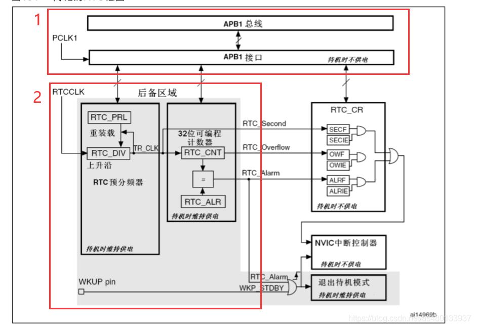
- APB1接口:用来和APB1总线相连。通过APB1接口可以访问RTC的相关寄存器(预分频值,计数器值,闹钟值)。
- RTC核心:由一组可编程计数器组成。分两个主要模块。
第一个是RTC预分频模块,它可以编程产生最长1秒的RTC时间基TR_CLK。如果设置了秒中断允许位,可以产生秒中断。
第二个是32位的可编程计数器,可被初始化为当前时间。系统时间按TR_CLK周期累加并与存储在RTC_ALR寄存器中的可编程时间相比,当匹配时候如果设置了闹钟中断允许位,可以产生闹钟中断。
二、使用STM32CubeMX建立工程
了解实时时钟RTC的原理。STM32芯片自带RTC,因此不须像其他MCU需外接RTC模块。请编程实现STM32的日历读取、设置和输出。要求:
- 1)读取RTC初始时间,验证是否为 1970年1月1日零分零秒;
- 2)将RTC时间调整为当前时间,并以 2021年x月x日x分x秒的格式从串口输出(或输出到OLED屏),每1s改变一次;
- 3)如果输出内容中需加入“星期x”,请修改代码。
- 选择
STM32F103C8芯片

- 配置
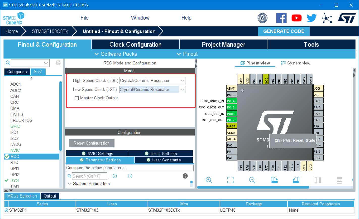
RCC:
-
配置
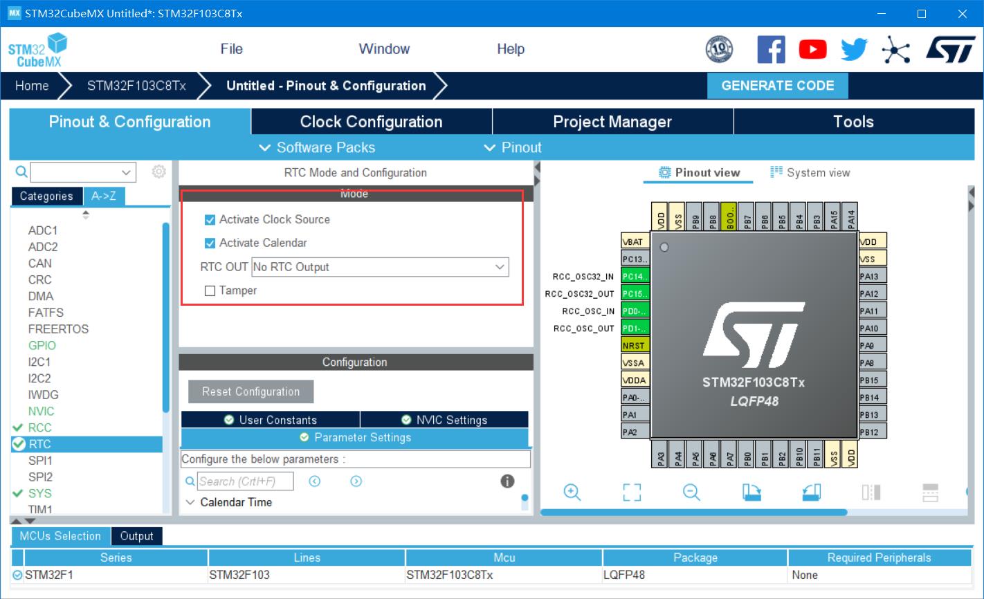
RTC:
-
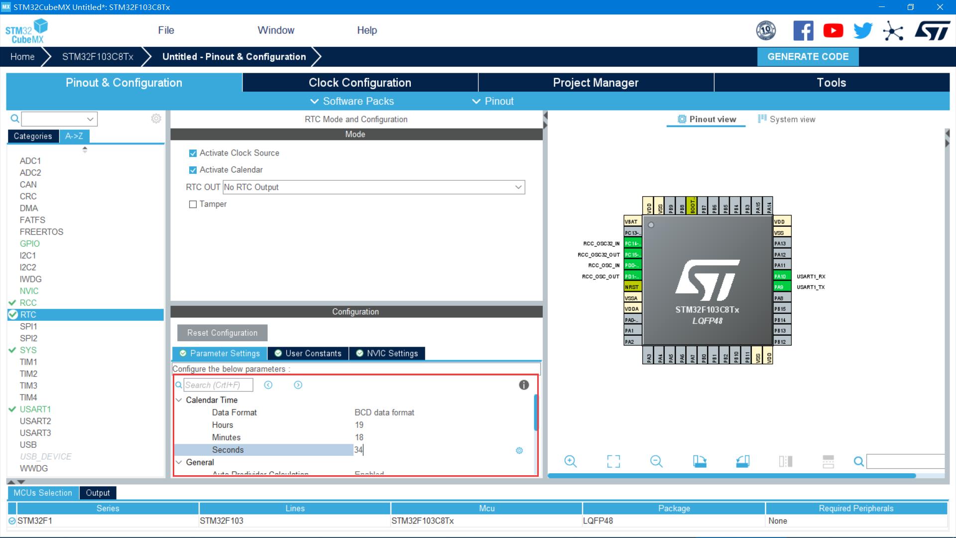
设置初始时间:
-
配置
USART1:

生成项目:

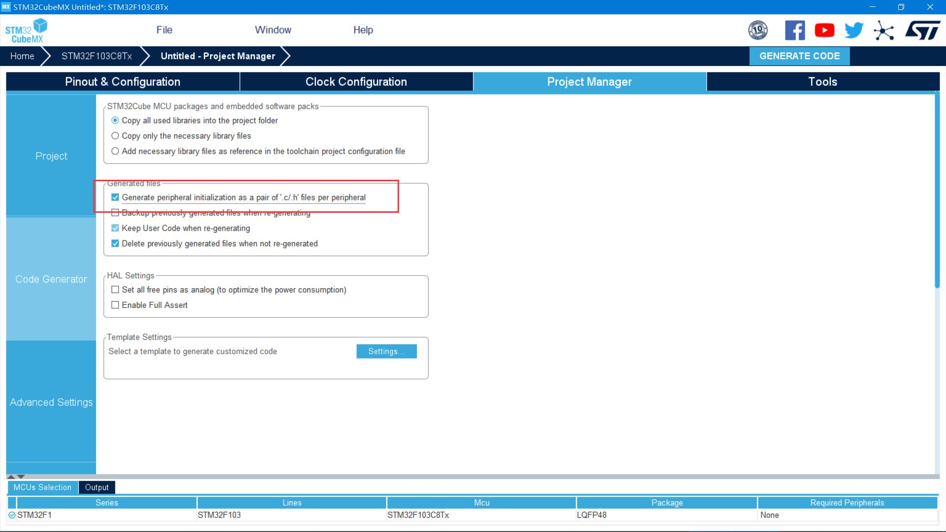
三、代码部分
打开魔法棒->target->勾选use microlib

main.c:
/* USER CODE BEGIN Header */
/**
******************************************************************************
* @file : main.c
* @brief : Main program body
******************************************************************************
* @attention
*
* <h2><center>© Copyright (c) 2021 STMicroelectronics.
* All rights reserved.</center></h2>
*
* This software component is licensed by ST under BSD 3-Clause license,
* the "License"; You may not use this file except in compliance with the
* License. You may obtain a copy of the License at:
* opensource.org/licenses/BSD-3-Clause
*
******************************************************************************
*/
/* USER CODE END Header */
/* Includes ------------------------------------------------------------------*/
#include "main.h"
#include "rtc.h"
#include "usart.h"
#include "gpio.h"
#include "stdio.h"
int fputc(int ch,FILE *f)
uint8_t temp[1]=ch;
HAL_UART_Transmit(&huart1,temp,1,2);
return ch;
/* Private includes ----------------------------------------------------------*/
/* USER CODE BEGIN Includes */
/* USER CODE END Includes */
/* Private typedef -----------------------------------------------------------*/
/* USER CODE BEGIN PTD */
/* USER CODE END PTD */
/* Private define ------------------------------------------------------------*/
/* USER CODE BEGIN PD */
/* USER CODE END PD */
/* Private macro -------------------------------------------------------------*/
/* USER CODE BEGIN PM */
/* USER CODE END PM */
/* Private variables ---------------------------------------------------------*/
/* USER CODE BEGIN PV */
/* USER CODE END PV */
/* Private function prototypes -----------------------------------------------*/
void SystemClock_Config(void);
/* USER CODE BEGIN PFP */
/* USER CODE END PFP */
/* Private user code ---------------------------------------------------------*/
/* USER CODE BEGIN 0 */
/* USER CODE END 0 */
/**
* @brief The application entry point.
* @retval int
*/
int main(void)
/* USER CODE BEGIN 1 */
RTC_DateTypeDef GetData; //获取日期结构体
RTC_TimeTypeDef GetTime; //获取时间结构体
/* USER CODE END 1 */
/* MCU Configuration--------------------------------------------------------*/
/* Reset of all peripherals, Initializes the Flash interface and the Systick. */
HAL_Init();
/* USER CODE BEGIN Init */
/* USER CODE END Init */
/* Configure the system clock */
SystemClock_Config();
/* USER CODE BEGIN SysInit */
/* USER CODE END SysInit */
/* Initialize all configured peripherals */
MX_GPIO_Init();
MX_RTC_Init();
MX_USART1_UART_Init();
/* USER CODE BEGIN 2 */
/* USER CODE END 2 */
/* Infinite loop */
/* USER CODE BEGIN WHILE */
while (1)
/* USER CODE END WHILE */
/* Get the RTC current Time */
HAL_RTC_GetTime(&hrtc, &GetTime, RTC_FORMAT_BIN);//获取时间
/* Get the RTC current Date */
HAL_RTC_GetDate(&hrtc, &GetData, RTC_FORMAT_BIN);//获取日期
/* Display date Format : yy/mm/dd */
printf("%02d/%02d/%02d\\r\\n",2000 + GetData.Year, GetData.Month, GetData.Date);
/* Display time Format : hh:mm:ss */
printf("%02d:%02d:%02d\\r\\n",GetTime.Hours, GetTime.Minutes, GetTime.Seconds);
printf("\\r\\n");
HAL_Delay(1000);
/* USER CODE BEGIN 3 */
/* USER CODE END 3 */
/**
* @brief System Clock Configuration
* @retval None
*/
void SystemClock_Config(void)
RCC_OscInitTypeDef RCC_OscInitStruct = 0;
RCC_ClkInitTypeDef RCC_ClkInitStruct = 0;
RCC_PeriphCLKInitTypeDef PeriphClkInit = 0;
/** Initializes the RCC Oscillators according to the specified parameters
* in the RCC_OscInitTypeDef structure.
*/
RCC_OscInitStruct.OscillatorType = RCC_OSCILLATORTYPE_HSE|RCC_OSCILLATORTYPE_LSE;
RCC_OscInitStruct.HSEState = RCC_HSE_ON;
RCC_OscInitStruct.HSEPredivValue = RCC_HSE_PREDIV_DIV1;
RCC_OscInitStruct.LSEState = RCC_LSE_ON;
RCC_OscInitStruct.HSIState = RCC_HSI_ON;
RCC_OscInitStruct.PLL.PLLState = RCC_PLL_ON;
RCC_OscInitStruct.PLL.PLLSource = RCC_PLLSOURCE_HSE;
RCC_OscInitStruct.PLL.PLLMUL = RCC_PLL_MUL9;
if (HAL_RCC_OscConfig(&RCC_OscInitStruct) != HAL_OK)
Error_Handler();
/** Initializes the CPU, AHB and APB buses clocks
*/
RCC_ClkInitStruct.ClockType = RCC_CLOCKTYPE_HCLK|RCC_CLOCKTYPE_SYSCLK
|RCC_CLOCKTYPE_PCLK1|RCC_CLOCKTYPE_PCLK2;
RCC_ClkInitStruct.SYSCLKSource = RCC_SYSCLKSOURCE_PLLCLK;
RCC_ClkInitStruct.AHBCLKDivider = RCC_SYSCLK_DIV1;
RCC_ClkInitStruct.APB1CLKDivider = RCC_HCLK_DIV2;
RCC_ClkInitStruct.APB2CLKDivider = RCC_HCLK_DIV1;
if (HAL_RCC_ClockConfig(&RCC_ClkInitStruct, FLASH_LATENCY_2) != HAL_OK)
Error_Handler();
PeriphClkInit.PeriphClockSelection = RCC_PERIPHCLK_RTC;
PeriphClkInit.RTCClockSelection = RCC_RTCCLKSOURCE_LSE;
if (HAL_RCCEx_PeriphCLKConfig(&PeriphClkInit) != HAL_OK)
Error_Handler();
/* USER CODE BEGIN 4 */
/* USER CODE END 4 */
/**
* @brief This function is executed in case of error occurrence.
* @retval None
*/
void Error_Handler(void)
/* USER CODE BEGIN Error_Handler_Debug */
/* User can add his own implementation to report the HAL error return state */
__disable_irq();
while (1)
/* USER CODE END Error_Handler_Debug */
#ifdef USE_FULL_ASSERT
/**
* @brief Reports the name of the source file and the source line number
* where the assert_param error has occurred.
* @param file: pointer to the source file name
* @param line: assert_param error line source number
* @retval None
*/
void assert_failed(uint8_t *file, uint32_t line)
/* USER CODE BEGIN 6 */
/* User can add his own implementation to report the file name and line number,
ex: printf("Wrong parameters value: file %s on line %d\\r\\n", file, line) */
/* USER CODE END 6 */
#endif /* USE_FULL_ASSERT */
/************************ (C) COPYRIGHT STMicroelectronics *****END OF FILE****/
运行效果:

四、总结
介绍了实时时钟RTC的原理,实现了STM32F103C8的日历读取、设置和输出。
五、参考链接
以上是关于基于实时时钟RTC实现STM32F103C8的日历读取设置和输出的主要内容,如果未能解决你的问题,请参考以下文章