乐鑫esp8266模块MicroPython开发板MQTT物联网人工智能最小系统
Posted 卓晴
tags:
篇首语:本文由小常识网(cha138.com)小编为大家整理,主要介绍了乐鑫esp8266模块MicroPython开发板MQTT物联网人工智能最小系统相关的知识,希望对你有一定的参考价值。
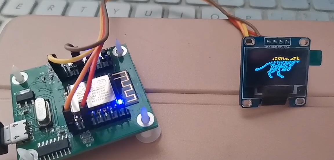
简 介: ※对于购买自网络的基于
ESP8266的实验模块进行了初步的测试,它其中的一些示例进行了练习。特别是对于基于ESP8266的特殊的一些外设的测试。
关键词: ESP8266,MicroPython
§01 esp8266模块
一、背景介绍
从TB购买到 乐鑫esp8266模块MicroPython开发板MQTT物联网人工智能最小系统 。下面对于它进行初步测试。
1、模块套件
模块的套件包括主板以及I2C的OLED显示模块。
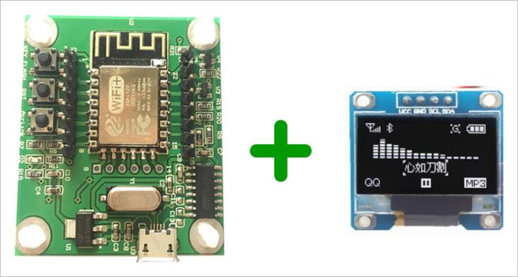
▲ 图1.1.1 购买到的模块
(1)资料下载
▲ 图1.1.2 与销售商的对话
hi,这是我用百度网盘分享的文件~复制这段内容打开「百度网盘」APP即可获取。
- 链接: https://pan.baidu.com/s/1hA-FbQrO2pdcm-idR7OpEw
- 提取码:6666
(2)下载目录
1.MicroPython之LED闪烁
2.MicroPython之按键
3.MicroPython之外部中断
4.MicroPython之定时器
5.MicroPython之I2C总线OLED显示屏
6. MicroPython之RTC实时时钟
7. MicroPython之ADC
8.MicroPython之PWM呼吸灯
9.MicroPython之连接无线路由器
10.MicroPython之Socket通信
12.MicroPython之开源项目8266动画animation_on_esp8266
CH340_341驱动
MicroPython视频教程
python基本方法.docx
动画演示.mp4
技术交流群.txt
开发板原理图.pdf
专用播放器解压密码123456.rar
2、接入USB
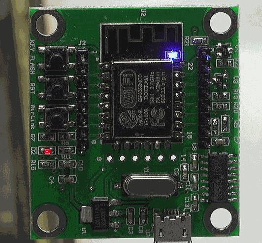
可以看到模块上面使用CH340作为USB-UART转接。接入电脑后可以看到电脑设备中出现 虚拟串口。
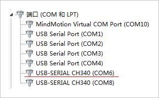
▲ 图1.1.3 电脑中的USB虚拟串口
3、电路板原理图
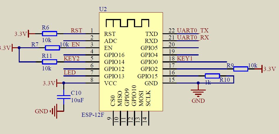
▲ 图1.1.4 核心板管脚定义
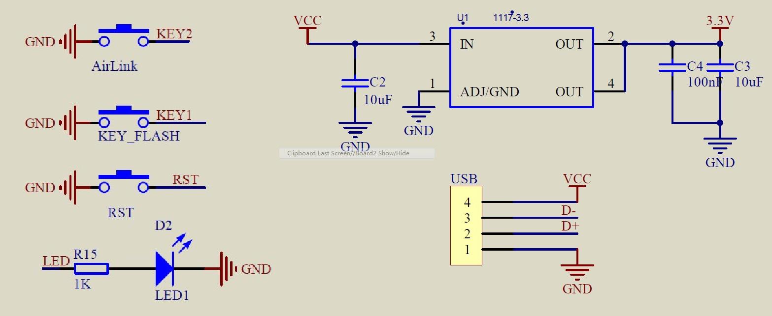
▲ 图1.1.5 按键与电源
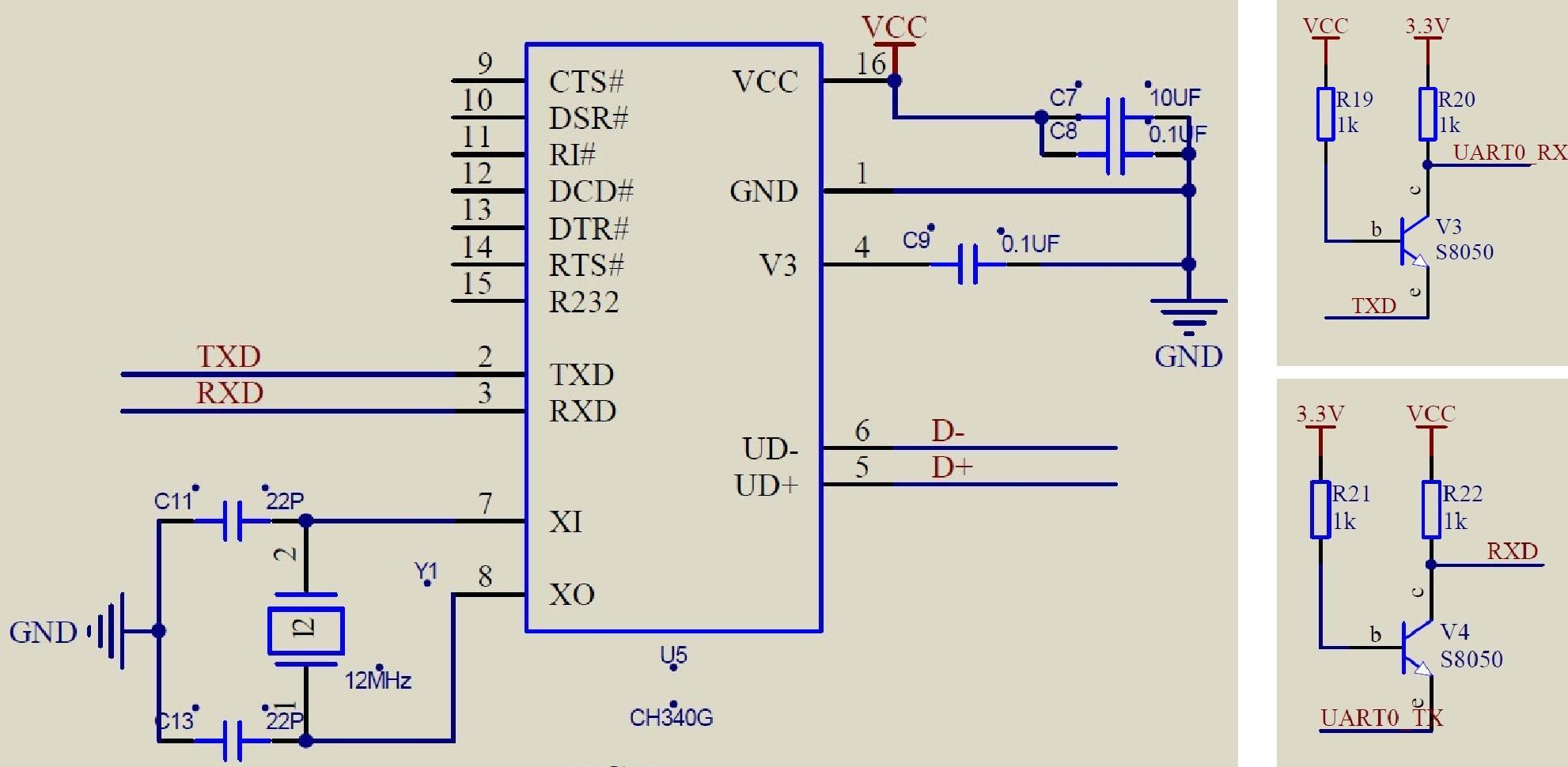
▲ 图1.1.6 USB 与下载电路
二、调试MicroPython
基于串口REPL可以对ESP8266模块进行MicroPython编程。REPL 的操作界面使用STM32Bootloader。 对于STM32Bootloader 网络命令MPDLD进行改造。在下载MicroPython程序之前通过发送 Ctrl+C(0x3)使得程序从前执行程序中返回。
1、Help()信息
MicroPython v1.11-8-g48dcbbe60 on 2019-05-29; ESP module with ESP8266
Type "help()" for more information.
>>> help()
Welcome to MicroPython!

For online docs please visit http://docs.micropython.org/en/latest/esp8266/ .
For diagnostic information to include in bug reports execute 'import port_diag'.

Basic WiFi configuration:

import network
sta_if = network.WLAN(network.STA_IF); sta_if.active(True)
sta_if.scan()                             # Scan for available access points
sta_if.connect("<AP_name>", "<password>") # Connect to an AP
sta_if.isconnected()                      # Check for successful connection
# Change name/password of ESP8266's AP:
ap_if = network.WLAN(network.AP_IF)
ap_if.config(essid="<AP_NAME>", authmode=network.AUTH_WPA_WPA2_PSK, password="<password>")

Control commands:
  CTRL-A        -- on a blank line, enter raw REPL mode
  CTRL-B        -- on a blank line, enter normal REPL mode
  CTRL-C        -- interrupt a running program
  CTRL-D        -- on a blank line, do a soft reset of the board
  CTRL-E        -- on a blank line, enter paste mode

For further help on a specific object, type help(obj)
>>>
2、基本程序
from machine                import Pin
import time

while True:
    print("Hello.")
    time.sleep_ms(200)
程序下载之后,在串口的REPL中重复显示:“hello”
§02 基础测试
一、基础测试
1、测试LED
(1)测试代码
from machine                import Pin
import time

led = Pin(2, Pin.OUT)

while True:
    led(1)
    time.sleep(0.5)
    led(0)
    time.sleep(0.5)
(2)结果
▲ 图2.1.1 LED闪烁
2、测试按键
(1)测试代码
电路板上有两个按钮:KEY1:GPIO0, KEY2:GPIO14
from machine                import Pin
import time

led = Pin(2, Pin.OUT)
key = Pin(0, Pin.IN, Pin.PULL_UP)
state = 1

print("Press key to change LED state....")

while True:
    if key.value() == 0:
        time.sleep_ms(10)
        if key.value() == 0:
            state = not state
            led(state)

            while not key.value():
                pass
(2)测试结果
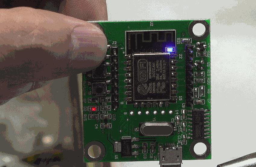
▲ 图2.1.2 测试按键结果
将上面的key定义修改成:
key = Pin(14, Pin.IN, Pin.PULL_UP)
可以使用另外一个按钮来切换LED的状态。
3、测试外部重点
(1)测试代码
from machine                import Pin
import time

led = Pin(2, Pin.OUT)
key = Pin(14, Pin.IN, Pin.PULL_UP)
state = 1

print("Press key to change LED state....")

def fun(key):
    global state

    time.sleep_ms(10)

    if key.value() == 0:
        state = not state
        led.value(state)

key.irq(fun, Pin.IRQ_FALLING)
(2)测试结果
按动KEY2可以切换LED状态。
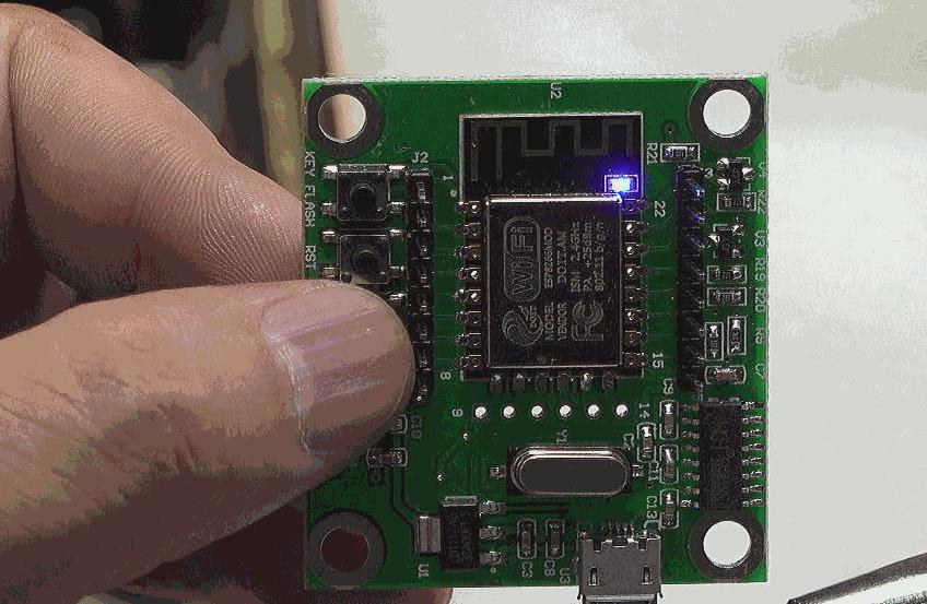
▲ 图2.1.3 按动KEY2可以切换LED状态
4、测试定时器
from machine                import Pin,Timer
import time

led = Pin(2, Pin.OUT)
count = 1

print("Change LED state....")

def fun(tim):
    global count

    count += 4
    print(count)
    led.value(count%2)

tim = Timer(-1)
tim.init(period=500, mode=Timer.PERIODIC, callback=fun)
周期输出打印的字符。
5、测试OLED
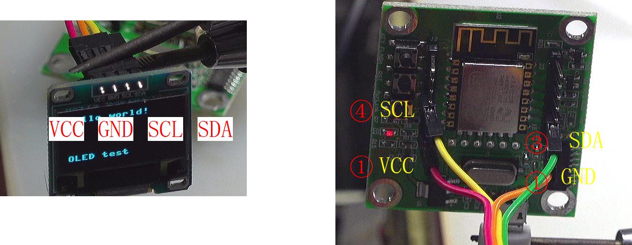
▲ 图2.1.4 OLED与ESP8266连接关系
(1)测试代码
from machine import Pin,Timer,I2C
import time
from micropython import const
import framebuf
SET_CONTRAST = const(0x81)
SET_ENTIRE_ON = const(0xa4)
SET_NORM_INV = const(0xa6)
SET_DISP = const(0xae)
SET_MEM_ADDR = const(0x20)
SET_COL_ADDR = const(0x21)
SET_PAGE_ADDR = const(0x22)
SET_DISP_START_LINE = const(0x40)
SET_SEG_REMAP = const(0xa0)
SET_MUX_RATIO = const(0xa8)
SET_COM_OUT_DIR = const(0xc0)
SET_DISP_OFFSET = const(0xd3)
SET_COM_PIN_CFG = const(0xda)
SET_DISP_CLK_DIV = const(0xd5)
SET_PRECHARGE = const(0xd9)
SET_VCOM_DESEL = const(0xdb)
SET_CHARGE_PUMP = const(0x8d)
class SSD1306(framebuf.FrameBuffer):
def __init__(self, width, height, external_vcc):
self.width = width
self.height = height
self.external_vcc = external_vcc
self.pages = self.height // 8
self.buffer = bytearray(self.pages * self.width)
super().__init__(self.buffer, self.width, self.height, framebuf.MONO_VLSB)
self.init_display()
def init_display(self):
for cmd in (
SET_DISP | 0x00, # off
SET_MEM_ADDR, 0x00, # horizontal
SET_DISP_START_LINE | 0x00,
SET_SEG_REMAP | 0x01, # column addr 127 mapped to SEG0
SET_MUX_RATIO, self.height - 1,
SET_COM_OUT_DIR | 0x08, # scan from COM[N] to COM0
SET_DISP_OFFSET, 0x00,
SET_COM_PIN_CFG, 0x02 if self.height == 32 else 0x12,
SET_DISP_CLK_DIV, 0x80,
SET_PRECHARGE, 0x22 if self.external_vcc else 0xf1,
SET_VCOM_DESEL, 0x30, # 0.83*Vcc
SET_CONTRAST, 0xff, # maximum
SET_ENTIRE_ON, # output follows RAM contents
SET_NORM_INV, # not inverted
SET_CHARGE_PUMP, 0x10 if self.external_vcc else 0x14,
SET_DISP | 0x01): # on
self.write_cmd(cmd)
self.fill(0)
self.show()
def poweroff(self):
self.write_cmd(SET_DISP | 0x00)
def poweron(self):
self.write_cmd(SET_DISP | 0x01)
def contrast(self, contrast):
self.write_cmd(SET_CONTRAST)
self.write_cmd(contrast)
def invert(self, invert):
self.write_cmd(SET_NORM_INV | (invert & 1))
def show(self):
x0 = 0
x1 = self.width - 1
if self.width == 64:
x0 += 32
x1 += 32
self.write_cmd(SET_COL_ADDR)
self.write_cmd(x0)
self.write_cmd(x1)
self.write_cmd(SET_PAGE_ADDR)
self.write_cmd(0)
self.write_cmd(self.pages - 1)
self.write_data(self.buffer)
class SSD1306_I2C(SSD1306):
def __init__(self, width, height, i2c, addr=0x3c, external_vcc=False):
self.i2c = i2c
self.addr = addr
self.temp = bytearray(2)
super().__init__(width, height, external_vcc)
def write_cmd(self, cmd):
self.temp[0] = 0x80 # Co=1, D/C#=0
self.temp[1] = cmd
self.i2c.writeto(self.addr, self.temp)
def write_data(self, buf):
self.temp[0] = self.addr << 1
self.temp[1] = 0x40 # Co=0, D/C#=1
self