AirSim动态 | 还在为AirSim中配置传感器而烦恼吗?
Posted 阿木实验室
tags:
篇首语:本文由小常识网(cha138.com)小编为大家整理,主要介绍了AirSim动态 | 还在为AirSim中配置传感器而烦恼吗?相关的知识,希望对你有一定的参考价值。
导语 AirSim中自带相机吗?怎么采集数据进行识别呢?我要单独添加别的传感器模块吗?你是否也有相同的疑惑呢,本篇文章带你了解AirSim中的传感器。IMU模块,相机模块还有激光雷达等传感器都在AirSim中有相关的配置。
一、AirSim 中的传感器
AirSim 目前支持以下传感器。每个传感器都与指定其传感器类型的整数枚举相关联。
- 相机
- 气压计 = 1
- IMU = 2
- GPS = 3
- 磁力计 = 4
- 距离传感器 = 5
- 激光雷达 = 6
注意:相机的配置与其他传感器不同,并且没有与之关联的枚举。 可以查看相机配置和API相机图像去进行相关配置。 相机配置: https://microsoft.github.io/AirSim/settings/
图像API: https://microsoft.github.io/AirSim/image_apis/
二、默认传感器 如果所需要的传感器在【settings.json】文件中未指定,则可以在默认情况下改变以下三种sim模式,启用相关传感器
- Multirotor (多旋翼)
- IMU
- 磁力计
- GPS
- 气压计
- Car(车辆)
- GPS
- ComputerVision(计算机视觉)
- 无传感器
除此之外,可以使用“createDefaultSensorSettings”方法在【AirSimSettings.cpp】文件中设置在默认参数下各个传感器。
配置默认传感器列表 可以在【settings.json】中配置默认传感器列表: "DefaultSensors": { "Barometer": { "SensorType": 1, "Enabled" : true, "PressureFactorSigma": 0.001825, "PressureFactorTau": 3600, "UncorrelatedNoiseSigma": 2.7, "UpdateLatency": 0, "UpdateFrequency": 50, "StartupDelay": 0
},
"Imu": {
    "SensorType": 2,
    "Enabled" : true,
    "AngularRandomWalk": 0.3,
    "GyroBiasStabilityTau": 500,
    "GyroBiasStability": 4.6,
    "VelocityRandomWalk": 0.24,
    "AccelBiasStabilityTau": 800,
    "AccelBiasStability": 36
},
"Gps": {
    "SensorType": 3,
    "Enabled" : true,
    "EphTimeConstant": 0.9,
    "EpvTimeConstant": 0.9,
    "EphInitial": 25,
    "EpvInitial": 25,
    "EphFinal": 0.1,
    "EpvFinal": 0.1,
    "EphMin3d": 3,
    "EphMin2d": 4,
    "UpdateLatency": 0.2,
    "UpdateFrequency": 50,
    "StartupDelay": 1
},
"Magnetometer": {
    "SensorType": 4,
    "Enabled" : true,
    "NoiseSigma": 0.005,
    "ScaleFactor": 1,
    "NoiseBias": 0,
    "UpdateLatency": 0,
    "UpdateFrequency": 50,
    "StartupDelay": 0
},
"Distance": {
    "SensorType": 5,
    "Enabled" : true,
    "MinDistance": 0.2,
    "MaxDistance": 40,
    "X": 0, "Y": 0, "Z": -1,
    "Yaw": 0, "Pitch": 0, "Roll": 0,
    "DrawDebugPoints": false
},
"Lidar2": {
    "SensorType": 6,
    "Enabled" : true,
    "NumberOfChannels": 16,
    "RotationsPerSecond": 10,
    "PointsPerSecond": 100000,
    "X": 0, "Y": 0, "Z": -1,
    "Roll": 0, "Pitch": 0, "Yaw" : 0,
    "VerticalFOVUpper": -15,
    "VerticalFOVLower": -25,
    "HorizontalFOVStart": -20,
    "HorizontalFOVEnd": 20,
    "DrawDebugPoints": true,
    "DataFrame": "SensorLocalFrame"
}
},
三、配置车辆专用传感器列表 车辆传感器可以覆盖上面列出的所有默认传感器。但是在默认情况下,激光雷达和距离传感器不会添加到车辆中,需要通过别的方式进行添加。
每个传感器都必须有一个有效的“SensorType”,并且可以定义一个属性子集来覆盖上面显示的默认值。在这里,可以将Enabled设置为false以禁用特定类型的传感器,比如下面:
"Vehicles": {
"Drone1": {
    "VehicleType": "SimpleFlight",
    "AutoCreate": true,
    ...
    "Sensors": {
        "Barometer":{
            "SensorType": 1,
            "Enabled": true,
            "PressureFactorSigma": 0.0001825
        },
        "MyLidar1": {
            "SensorType": 6,
            "Enabled" : true,
            "NumberOfChannels": 16,
            "PointsPerSecond": 10000,
            "X": 0, "Y": 0, "Z": -1,
            "DrawDebugPoints": true
        },
        "MyLidar2": {
            "SensorType": 6,
            "Enabled" : true,
            "NumberOfChannels": 4,
            "PointsPerSecond": 10000,
            "X": 0, "Y": 0, "Z": -1,
            "DrawDebugPoints": true
        }
    }
}
}
注意:有关“激光雷达传感器”和“距离距离传感器”需要进行特定的设置。
四、调试 - 服务器端可视化 在默认情况下,距离传感器命中的点不会绘制在窗口中,所以要使用下面的代码,在【settings.json】文件中将“DrawDebugPoints”设置为enable,启用在可视窗口界面绘制命中点。
"Distance": { "SensorType": 5, "Enabled" : true, ... "DrawDebugPoints": true }
五、传感器API 下面将介绍一些传感器API的使用。大家也可以参考上期所给代码[hello_drone.py]和[hello_drone.cpp]其中相关例子,或者也可以查看下面API介绍。 (1)晴雨表 msr::airlib::BarometerBase::Output getBarometerData(const std::string& barometer_name, const std::string& vehicle_name);
barometer_data = client.getBarometerData(barometer_name = "", vehicle_name = "")
(2)IMU单元 msr::airlib::ImuBase::Output getImuData(const std::string& imu_name = "", const std::string& vehicle_name = "");
imu_data = client.getImuData(imu_name = "", vehicle_name = "")
(3)GPS msr::airlib::GpsBase::Output getGpsData(const std::string& gps_name = "", const std::string& vehicle_name = "");
gps_data = client.getGpsData(gps_name = "", vehicle_name = "")
(4)磁力计 msr::airlib::MagnetometerBase::Output getMagnetometerData(const std::string& magnetometer_name = "", const std::string& vehicle_name = "");
magnetometer_data = client.getMagnetometerData(magnetometer_name = "", vehicle_name = "")
(5)距离传感器 msr::airlib::DistanceSensorData getDistanceSensorData(const std::string& distance_sensor_name = "", const std::string& vehicle_name = "");
distance_sensor_data = client.getDistanceSensorData(distance_sensor_name = "", vehicle_name = "")
六、激光雷达传感器 AirSim支持多旋翼和汽车上配置激光雷达传感器。激光雷达的启用和其他通用传感器设置一样,具体内容可以看上文,这里就不做过多描述了。
如何在车辆上启用激光雷达
1.系统在默认情况下不启用激光雷达。 如若启用激光雷达则在【settings.json】文件中设置SensorType和Enabled的属性。
"Lidar1": { "SensorType": 6, "Enabled" : true, }
2.可以在车辆上启用多个激光雷达
3.激光雷达相关配置
可以在【setting.json】文件中配置以下参数。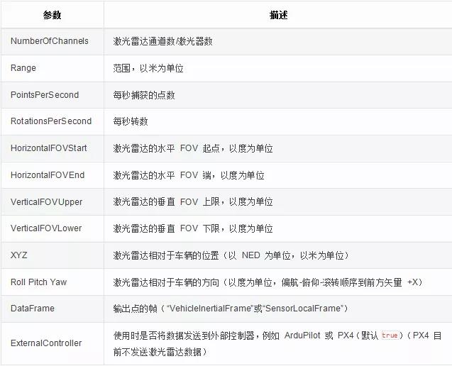
4.参考代码例子:
{ "SeeDocsAt": "https://microsoft.github.io/AirSim/settings/", "SettingsVersion": 1.2,
"SimMode": "Multirotor",

 "Vehicles": {
    "Drone1": {
        "VehicleType": "simpleflight",
        "AutoCreate": true,
        "Sensors": {
            "LidarSensor1": {
                "SensorType": 6,
                "Enabled" : true,
                "NumberOfChannels": 16,
                "RotationsPerSecond": 10,
                "PointsPerSecond": 100000,
                "X": 0, "Y": 0, "Z": -1,
                "Roll": 0, "Pitch": 0, "Yaw" : 0,
                "VerticalFOVUpper": -15,
                "VerticalFOVLower": -25,
                "HorizontalFOVStart": -20,
                "HorizontalFOVEnd": 20,
                "DrawDebugPoints": true,
                "DataFrame": "SensorLocalFrame"
            },
            "LidarSensor2": {
               "SensorType": 6,
                "Enabled" : true,
                "NumberOfChannels": 4,
                "RotationsPerSecond": 10,
                "PointsPerSecond": 10000,
                "X": 0, "Y": 0, "Z": -1,
                "Roll": 0, "Pitch": 0, "Yaw" : 0,
                "VerticalFOVUpper": -15,
                "VerticalFOVLower": -25,
                "DrawDebugPoints": true,
                "DataFrame": "SensorLocalFrame"
            }
        }
    }
}
}
七、调试服务器端可视化
默认情况下,不在视口上会绘制激光雷达点。如要在视口上启用命中激光点的绘制,可以通过【setting.json】启用设置【DrawDebugPoints】。
"Lidar1": { ... "DrawDebugPoints": true },
注意:启动【DrawDebugPoints】可能导致使用过多内存而使v1.3.1版本和v1.3.0版本奔溃。但是这些问题已经在master中修复并且在后续版本中也可以正常工作。** 八、客户端可用API接口** 可以使用getLidarData() API检索激光雷达数据。 API返回一个Point-Cloud,作为一个带有捕获时间戳和激光雷达姿态的平面浮动数组,
点云:*
a)浮点数表示上次扫描范围内每个点的[x,y,z]坐标。
b)输出中的点的帧可以使用“DataFrame”属性进行配置:
1) "" 或VehicleInertialFrame-- 默认;返回点位于车辆惯性系中(以 NED 为单位,以米为单位)
2)SensorLocalFrame -- 返回点位于激光雷达局部坐标系中(以 NED 为单位,以米为单位)
- Lidar Pose: a)车辆惯性系中的激光雷达姿态(以 NED 为单位,以米为单位) b)可用于将点转换为其他帧。
Segmentation:对每个激光雷达点的碰撞对象进行分割。
一些有关Python的实例:
drone_lidar.py: https://github.com/microsoft/AirSim/blob/master/PythonClient/multirotor/drone_lidar.py
car_lidar.py: https://github.com/microsoft/AirSim/blob/master/PythonClient/car/car_lidar.py
Sensorframe_lidar_pointcloud.py: https://github.com/microsoft/AirSim/blob/master/PythonClient/multirotor/sensorframe_lidar_pointcloud.py
Vehicleframe_lidar_pointcloud.py: https://github.com/microsoft/AirSim/blob/master/PythonClient/multirotor/vehicleframe_lidar_pointcloud.py
官方资料:
1.本期PX4更新内容网址:https://microsoft.github.io/AirSim/sensors/
2.激光雷达配置:https://microsoft.github.io/AirSim/lidar/
3.距离传感器配置:https://microsoft.github.io/AirSim/distance_sensor/
4.红外传感器配置:https://microsoft.github.io/AirSim/InfraredCamera/
- End -
技术发展的日新月异,阿木实验室将紧跟技术的脚步,不断把机器人行业最新的技术和硬件推荐给大家。看到经过我们培训的学员在技术上突飞猛进,是我们培训最大的价值。如果你在机器人行业,就请关注我们的公众号,我们将持续发布机器人行业最有价值的信息和技术。 阿木实验室致力于前沿IT科技的教育和智能装备,让机器人研发更高效!
以上是关于AirSim动态 | 还在为AirSim中配置传感器而烦恼吗?的主要内容,如果未能解决你的问题,请参考以下文章