NanoPi NEO Air使用十一:编写SPI驱动点亮TFT屏幕,ST7789V
Posted qlexcel
tags:
篇首语:本文由小常识网(cha138.com)小编为大家整理,主要介绍了NanoPi NEO Air使用十一:编写SPI驱动点亮TFT屏幕,ST7789V相关的知识,希望对你有一定的参考价值。
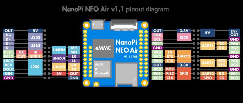
开发板引出来了spi0

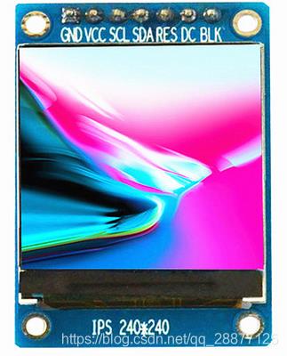
本节用spi0驱动一个spi接口的屏幕,屏幕如下:

240x240分辨率,1.3寸,主控为ST7789V。

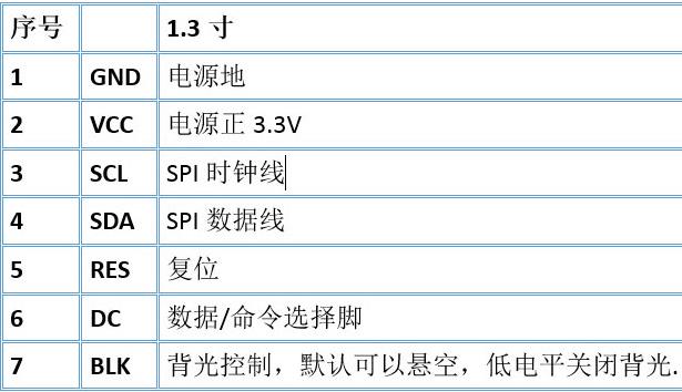
与开发板的引脚连接确定如下:
| 功能 | IO |
|---|---|
| GND | Pin6 |
| 5V | Pin2 |
| LCD_RESET | Pin7-PG11 |
| LCD_DC | Pin22-PA1 |
| SPICLK | Pin23-PC2 |
| SPIMOSI | Pin19-PC0 |
修改设备树
spi0节点定义在/home/ql/linux/H3/linux/arch/arm/boot/dts/sun8i-h3-nanopi.dtsi文件中,修改为:
&spi0 {
	/* needed to avoid dtc warning */
	#address-cells = <1>;
	#size-cells = <0>;

	status = "okay";
	pinctrl-names = "default";
	pinctrl-0 = <&spi0_pins &spi0_cs_pins>;
	cs-gpios = <&pio 2 3 GPIO_ACTIVE_HIGH>, <&pio 0 6 GPIO_ACTIVE_HIGH>; /*SPI-CS:PC3 and PA6*/

	pitft: pitft@0{
		compatible = "testspiTFT";
		reg = <0>;
		status = "okay";

		spi-max-frequency = <50000000>;
		rotate = <90>;
		fps = <33>;
		buswidth = <8>;
		debug = <0x0>;
	};
};
spi0节点的pinctrl-0属性来指示使用的引脚和功能,它的值为<&spi0_pins &spi0_cs_pins>,spi0_pins是pio的子节点,定义如下:
		pio: pinctrl@01c20800 {
			/* compatible is in per SoC .dtsi file */
			reg = <0x01c20800 0x400>;
			interrupts = <GIC_SPI 11 IRQ_TYPE_LEVEL_HIGH>,
				     <GIC_SPI 17 IRQ_TYPE_LEVEL_HIGH>;
			clocks = <&ccu CLK_BUS_PIO>, <&osc24M>, <&osc32k>;
			clock-names = "apb", "hosc", "losc";
			gpio-controller;
			#gpio-cells = <3>;
			interrupt-controller;
			#interrupt-cells = <3>;

			csi_pins: csi {
				pins = "PE0", "PE1", "PE2", "PE3", "PE4",
				       "PE5", "PE6", "PE7", "PE8", "PE9",
				       "PE10", "PE11";
				function = "csi";
			};

......

			spi0_pins: spi0 {
				pins = "PC0", "PC1", "PC2", "PC3";
				function = "spi0";
			};

			spi1_pins: spi1 {
				pins = "PA15", "PA16", "PA14", "PA13";
				function = "spi1";
			};

			uart0_pins_a: uart0@0 {
				pins = "PA4", "PA5";
				function = "uart0";
			};
......
		};
spi0_cs_pins在下面和DC引脚、RESET引脚定义在一起:
在根节点下添加DC引脚和RESET引脚的节点:
	testTFTRes {
		compatible = "testTFTRes";
		pinctrl-names = "default";
		pinctrl-0 = <&pinctrl_testTFTRes>;
		gpios = <&pio 6 11 GPIO_ACTIVE_HIGH>; /* PG11 */
		status = "okay";
	};

	testTFTDc {
		compatible = "testTFTDc";
		pinctrl-names = "default";
		pinctrl-0 = <&pinctrl_testTFTDc>;
		gpios = <&pio 0 1 GPIO_ACTIVE_HIGH>; /* PA1 */
		status = "okay";
	};
在pio下添加pinctrl_testTFTRes、pinctrl_testTFTDc、spi0_cs_pins:
&pio {
	leds_npi: led_pins {
		pins = "PA10";
		function = "gpio_out";
	};

	pinctrl_testTFTRes: testTFTRes_pins {
		pins = "PG11";
		function = "gpio_out";
	};

	pinctrl_testTFTDc: testTFTDc_pins {
		pins = "PA1";
		function = "gpio_out";
	};

	spi0_cs_pins: spi0_cs_pins {
		pins = "PC3", "PA6";
		function = "gpio_out";
	};
};
修改完成后,可以在设备树文件中搜索“PG11”和“PA1”,看看有没有其他地方在使用这些IO。
/home/ql/linux/H3/linux/arch/arm/boot/dts/sun8i-h3-nanopi.dtsi文件最终修改为:
/*
* Copyright (C) 2016 James Pettigrew <james@innovum.com.au>
* Copyright (C) 2016 Milo Kim <woogyom.kim@gmail.com>
*
* This file is dual-licensed: you can use it either under the terms
* of the GPL or the X11 license, at your option. Note that this dual
* licensing only applies to this file, and not this project as a
* whole.
*
* a) This file is free software; you can redistribute it and/or
* modify it under the terms of the GNU General Public License as
* published by the Free Software Foundation; either version 2 of the
* License, or (at your option) any later version.
*
* This file is distributed in the hope that it will be useful,
* but WITHOUT ANY WARRANTY; without even the implied warranty of
* MERCHANTABILITY or FITNESS FOR A PARTICULAR PURPOSE. See the
* GNU General Public License for more details.
*
* Or, alternatively,
*
* b) Permission is hereby granted, free of charge, to any person
* obtaining a copy of this software and associated documentation
* files (the "Software"), to deal in the Software without
* restriction, including without limitation the rights to use,
* copy, modify, merge, publish, distribute, sublicense, and/or
* sell copies of the Software, and to permit persons to whom the
* Software is furnished to do so, subject to the following
* conditions:
*
* The above copyright notice and this permission notice shall be
* included in all copies or substantial portions of the Software.
*
* THE SOFTWARE IS PROVIDED "AS IS", WITHOUT WARRANTY OF ANY KIND,
* EXPRESS OR IMPLIED, INCLUDING BUT NOT LIMITED TO THE WARRANTIES
* OF MERCHANTABILITY, FITNESS FOR A PARTICULAR PURPOSE AND
* NONINFRINGEMENT. IN NO EVENT SHALL THE AUTHORS OR COPYRIGHT
* HOLDERS BE LIABLE FOR ANY CLAIM, DAMAGES OR OTHER LIABILITY,
* WHETHER IN AN ACTION OF CONTRACT, TORT OR OTHERWISE, ARISING
* FROM, OUT OF OR IN CONNECTION WITH THE SOFTWARE OR THE USE OR
* OTHER DEALINGS IN THE SOFTWARE.
*/
/dts-v1/;
#include "sun8i-h3.dtsi"
#include "sunxi-common-regulators.dtsi"
#include <dt-bindings/gpio/gpio.h>
#include <dt-bindings/input/input.h>
#include <dt-bindings/pinctrl/sun4i-a10.h>
#include <dt-bindings/thermal/thermal.h>
/ {
aliases {
serial0 = &uart0;
serial1 = &uart1;
serial2 = &uart2;
serial3 = &uart3;
i2c0 = &i2c0;
i2c1 = &i2c1;
i2c2 = &i2c2;
spi0 = &spi0;
spi1 = &spi1;
pwm0 = &pwm;
mmc0 = &mmc0;
mmc2 = &mmc2;
ethernet0 = &emac;
i2s0 = &i2s0;
pcm5102a = &pcm5102a;
//spidev0 = &spidev0;
//spiflash = &spiflash;
pitft = &pitft;
//pitft_ts = &pitft_ts;
ir = &ir;
};
chosen {
stdout-path = "serial0:115200n8";
};
connector {
compatible = "hdmi-connector";
type = "a";
port {
hdmi_con_in: endpoint {
remote-endpoint = <&hdmi_out_con>;
};
};
};
/*leds {
compatible = "gpio-leds";
pinctrl-names = "default";
pinctrl-0 = <&leds_npi>, <&leds_r_npi>;
status {
label = "status_led";
gpios = <&pio 0 10 GPIO_ACTIVE_HIGH>;
linux,default-trigger = "heartbeat";
};
pwr {
label = "LED2";
gpios = <&r_pio 0 10 GPIO_ACTIVE_HIGH>;
default-state = "on";
};
};*/
testleds {
compatible = "test-gpio-leds";
pinctrl-names = "default";
pinctrl-0 = <&leds_npi>;
gpios = <&pio 0 10 GPIO_ACTIVE_HIGH>;
status = "okay";
};
testTFTRes {
compatible = "testTFTRes";
pinctrl-names = "default";
pinctrl-0 = <&pinctrl_testTFTRes>;
gpios = <&pio 6 11 GPIO_ACTIVE_HIGH>; /* PG11 */
status = "okay";
};
testTFTDc {
compatible = "testTFTDc";
pinctrl-names = "default";
pinctrl-0 = <&pinctrl_testTFTDc>;
gpios = <&pio 0 1 GPIO_ACTIVE_HIGH>; /* PA1 */
status = "okay";
};
r_gpio_keys {
compatible = "gpio-keys";
input-name = "k1";
pinctrl-names = "default";
pinctrl-0 = <&sw_r_npi>;
k1 {
label = "k1";
linux,code = <KEY_POWER>;
gpios = <&r_pio 0 3 GPIO_ACTIVE_LOW>;
};
};
vdd_cpux: gpio-regulator {
compatible = "regulator-gpio";
regulator-name = "vdd-cpux";
regulator-type = "voltage";
regulator-boot-on;
regulator-always-on;
regulator-min-microvolt = <1100000>;
regulator-max-microvolt = <1300000>;
regulator-ramp-delay = <50>; /* 4ms */
gpios = <&r_pio 0 6 GPIO_ACTIVE_HIGH>;
gpios-states = <0x1>;
states = <1100000 0x0
1300000 0x1>;
};
pcm5102a: pcm5102a-codec {
#sound-dai-cells = <0>;
compatible = "ti,pcm5102a";
status = "disabled";
};
sound_i2s {
compatible = "simple-audio-card";
simple-audio-card,name = "I2S-master";
simple-audio-card,mclk-fs = <256>;
simple-audio-card,format = "i2s";
status = "okay";
simple-audio-card,cpu {
sound-dai = <&i2s0>;
};
simple-audio-card,codec {
sound-dai = <&pcm5102a>;
};
};
reg_vcc1v2: vcc1v2 {
compatible = "regulator-fixed";
regulator-name = "vcc1v2";
regulator-min-microvolt = <1200000>;
regulator-max-microvolt = <1200000>;
regulator-always-on;
regulator-boot-on;
vin-supply = <®_vcc5v0>;
gpio = <&r_pio 0 8 GPIO_ACTIVE_HIGH>; /* PL8 */
enable-active-high;
};
reg_vcc_dram: vcc-dram {
compatible = "regulator-fixed";
regulator-name = "vcc-dram";
regulator-min-microvolt = <1500000>;
regulator-max-microvolt = <1500000>;
regulator-always-on;
regulator-boot-on;
vin-supply = <®_vcc5v0>;
gpio = <&r_pio 0 9 GPIO_ACTIVE_HIGH>; /* PL9 */
enable-active-high;
};
reg_vdd_cpux: vdd-cpux {
compatible = "regulator-fixed";
regulator-name = "vdd-cpux-en";
regulator-min-microvolt = <1200000>;
regulator-max-microvolt = <1200000>;
regulator-always-on;
regulator-boot-on;
vin-supply = <®_vcc5v0>;
gpio = <&r_pio 0 8 GPIO_ACTIVE_HIGH>; /* PL8 */
enable-active-high;
};
};
&cpu0 {
operating-points = <
1008000 1300000
816000 1100000
624000 1100000
480000 1100000
>;
#cooling-cells = <2>;
cooling-min-level = <0>;
cooling-max-level = <3>;
cpu0-supply = <&vdd_cpux>;
};
&cpu_thermal {
trips {
cpu_warm: cpu_warm {
temperature = <60000>;
hysteresis = <2000>;
type = "passive";
};
cpu_hot: cpu_hot {
temperature = <70000>;
hysteresis = <2000>;
type = "passive";
};
cpu_very_hot: cpu_very_hot {
temperature = <80000>;
hysteresis = <2000>;
type = "passive";
};
cpu_crit: cpu_crit {
temperature = <100000>;
hysteresis = <2000>;
type = "critical";
};
};
cooling-maps {
cpu_warm_limit_cpu {
trip = <&cpu_warm>;
cooling-device = <&cpu0 THERMAL_NO_LIMIT 1>;
};
cpu_hot_limit_cpu {
trip = <&cpu_hot>;
cooling-device = <&cpu0 THERMAL_NO_LIMIT 2>;
};
cpu_very_hot_limit_cpu {
trip = <&cpu_very_hot>;
cooling-device = <&cpu0 3 THERMAL_NO_LIMIT>;
};
};
};
&ehci0 {
status = "okay";
};
&ohci0 {
status = "okay";
};
&ehci1 {
status = "okay";
};
&ohci1 {
status = "okay";
};
&ehci2 {
status = "okay";
};
&ohci2 {
status = "okay";
};
&ehci3 {
status = "okay";
};
&ohci3 {
status = "okay";
};
&mmc0 {
bus-width = <4>;
non-removable;
pinctrl-names = "default";
pinctrl-0 = <&mmc0_pins_a>, <&mmc0_cd_pin>;
boot_device = <0>;
status = "okay";
vmmc-supply = <®_vcc3v3>;
};
&mmc2 {
boot_device = <0>;
};
&pio {
leds_npi: led_pins {
pins = "PA10";
function = "gpio_out";
};
pinctrl_testTFTRes: testTFTRes_pins {
pins = "PG11";
function = "gpio_out";
};
pinctrl_testTFTDc: testTFTDc_pins {
pins = "PA1";
function = "gpio_out";
};
spi0_cs_pins: spi0_cs_pins {
pins = "PC3", "PA6";
function = "gpio_out";
};
};
&r_pio {
leds_r_npi: led_pins {
pins = "PL10";
function = "gpio_out";
};
sw_r_npi: key_pins {
pins = "PL3";
function = "gpio_in";
};
};
&uart0 {
pinctrl-names = "default";
pinctrl-0 = <&uart0_pins_a>;
status = "okay";
};
&uart1 {
pinctrl-names = "default";
pinctrl-0 = <&uart1_pins>;
status = "okay";
};
&uart2 {
pinctrl-names = "default";
pinctrl-0 = <&uart2_pins>;
status = "okay";
};
&uart3 {
pinctrl-names = "default";
pinctrl-0 = <&uart3_pins>, <&uart3_rts_cts_pins>;
status = "okay";
};
&i2c0 {
status = "okay";
rtc@68 {
compatible = "dallas,ds1307";
reg = <0x68>;
};
};
&i2c1 {
status = "okay";
};
&i2c2 {
status = "okay"以上是关于NanoPi NEO Air使用十一:编写SPI驱动点亮TFT屏幕,ST7789V的主要内容,如果未能解决你的问题,请参考以下文章