Linux LED子系统调试与应用 设备树官方文档与 gpio-leds.c 源码详解
Posted “逛丢一只鞋”
tags:
篇首语:本文由小常识网(cha138.com)小编为大家整理,主要介绍了Linux LED子系统调试与应用 设备树官方文档与 gpio-leds.c 源码详解相关的知识,希望对你有一定的参考价值。
前言
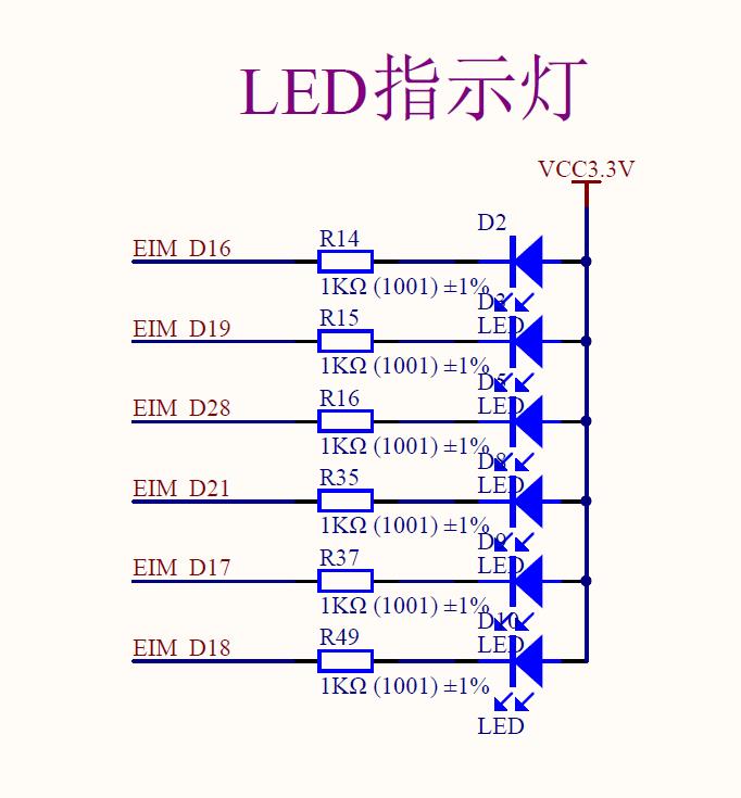
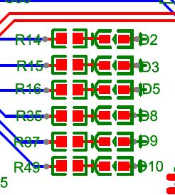
板子设计预留了六个LED灯,起初准备直接注册一个杂项设备进行控制
随后发现Linux内核中自带LED驱动,所以准备研究一下,也就有了这篇文章
Linux 内核自带LED 驱动
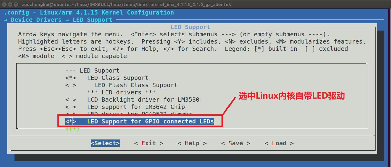
Linux 内核已经自带了LED 灯驱动,要使用Linux 内核自带的LED 灯驱动首先得先配置Linux 内核,使能自带的LED 灯驱动,输入如下命令打开Linux 配置菜单:
make menuconfig
按照如下路径打开LED 驱动配置项:
-> Device Drivers
-> LED Support (NEW_LEDS [=y])
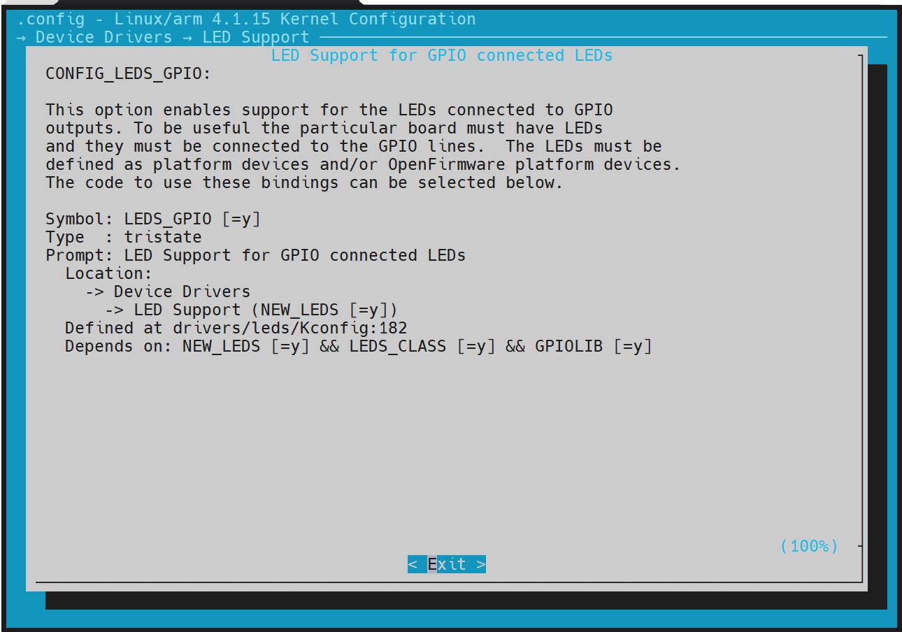
->LED Support for GPIO connected LEDs
按照上述路径,选择“LED Support for GPIO connected LEDs”,将其编译进Linux 内核,也即是在此选项上按下“Y”键,使此选项前面变为“<*>”,
查看官方说明文档
打开文档Documentation/devicetree/bindings/leds/leds-gpio.txt
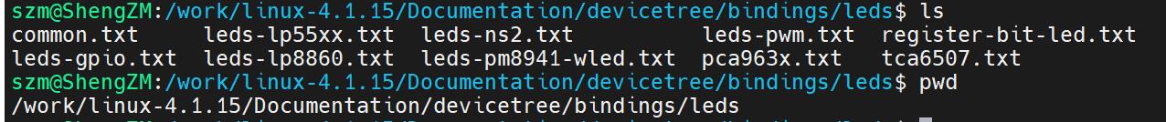
nano ./Documentation/devicetree/bindings/leds/leds-gpio.txt
此文档详细的讲解了Linux 自带驱动对应的设备树节点该如何编写
LEDs connected to GPIO lines

Required properties:
- compatible : should be "gpio-leds".

Each LED is represented as a sub-node of the gpio-leds device.  Each
node's name represents the name of the corresponding LED.

LED sub-node properties:
- gpios :  Should specify the LED's GPIO, see "gpios property" in
  Documentation/devicetree/bindings/gpio/gpio.txt.  Active low LEDs should be
  indicated using flags in the GPIO specifier.
- label :  (optional)
  see Documentation/devicetree/bindings/leds/common.txt
- linux,default-trigger :  (optional)
  see Documentation/devicetree/bindings/leds/common.txt
- default-state:  (optional) The initial state of the LED.  Valid
  values are "on", "off", and "keep".  If the LED is already on or off
  and the default-state property is set the to same value, then no
  glitch should be produced where the LED momentarily turns off (or
  on).  The "keep" setting will keep the LED at whatever its current
  state is, without producing a glitch.  The default is off if this
  property is not present.
- retain-state-suspended: (optional) The suspend state can be retained.Such
  as charge-led gpio.

Examples:

#include <dt-bindings/gpio/gpio.h>

leds {
	compatible = "gpio-leds";
	hdd {
		label = "IDE Activity";
		gpios = <&mcu_pio 0 GPIO_ACTIVE_LOW>;
		linux,default-trigger = "ide-disk";
	};

	fault {
		gpios = <&mcu_pio 1 GPIO_ACTIVE_HIGH>;
		/* Keep LED on if BIOS detected hardware fault */
		default-state = "keep";
	};
};

run-control {
	compatible = "gpio-leds";
	red {
		gpios = <&mpc8572 6 GPIO_ACTIVE_HIGH>;
		default-state = "off";
	};
	green {
		gpios = <&mpc8572 7 GPIO_ACTIVE_HIGH>;
		default-state = "on";
	};
};

leds {
	compatible = "gpio-leds";

	charger-led {
		gpios = <&gpio1 2 GPIO_ACTIVE_HIGH>;
		linux,default-trigger = "max8903-charger-charging";
		retain-state-suspended;
	};
};
对于该说明文档的解析:
①Required properties(必选)
Required properties:
-compatible : should be “gpio-leds”.
Each LED is represented as a sub-node of the gpio-leds device. Each node’s name represents the name of the corresponding LED.
dtsleds 节点的compatible 属性值一定要为 “gpio-leds”
②gpios(必选)
gpios : Should specify the LED’s GPIO, see “gpios property” in Documentation/devicetree/bindings/gpio/gpio.txt. Active low LEDs should be indicated using flags in the GPIO specifier.
gpios :创建一个节点表示LED 灯设备,比如dtsleds,如果板子上有多个LED 灯的话每个LED灯都作为dtsleds 的子节点。也就是每个LED表示为“gpio-leds”的一个子节点。
每个子节点设置gpios 属性值,表示此LED 所使用的GPIO 引脚!
具体gpios的属性设置,详情需要查看文档 Documentation/devicetree/bindings/gpio/gpio.txtLED的高低电平使用GPIO说明中的flag表示
GPIO说明文档
Specifying GPIO information for devices
============================================

1) gpios property
-----------------

Nodes that makes use of GPIOs should specify them using one or more
properties, each containing a 'gpio-list':

	gpio-list ::= <single-gpio> [gpio-list]
	single-gpio ::= <gpio-phandle> <gpio-specifier>
	gpio-phandle : phandle to gpio controller node
	gpio-specifier : Array of #gpio-cells specifying specific gpio
			 (controller specific)

GPIO properties should be named "[<name>-]gpios", with <name> being the purpose
of this GPIO for the device. While a non-existent <name> is considered valid
for compatibility reasons (resolving to the "gpios" property), it is not allowed
for new bindings.

GPIO properties can contain one or more GPIO phandles, but only in exceptional
cases should they contain more than one. If your device uses several GPIOs with
distinct functions, reference each of them under its own property, giving it a
meaningful name. The only case where an array of GPIOs is accepted is when
several GPIOs serve the same function (e.g. a parallel data line).

The exact purpose of each gpios property must be documented in the device tree
binding of the device.

The following example could be used to describe GPIO pins used as device enable
and bit-banged data signals:

	gpio1: gpio1 {
		gpio-controller
		 #gpio-cells = <2>;
	};
	gpio2: gpio2 {
		gpio-controller
		 #gpio-cells = <1>;
	};
	[...]

	enable-gpios = <&gpio2 2>;
	data-gpios = <&gpio1 12 0>,
		     <&gpio1 13 0>,
		     <&gpio1 14 0>,
		     <&gpio1 15 0>;

Note that gpio-specifier length is controller dependent.  In the
above example, &gpio1 uses 2 cells to specify a gpio, while &gpio2
only uses one.

gpio-specifier may encode: bank, pin position inside the bank,
whether pin is open-drain and whether pin is logically inverted.
Exact meaning of each specifier cell is controller specific, and must
be documented in the device tree binding for the device. Use the macros
defined in include/dt-bindings/gpio/gpio.h whenever possible:

Example of a node using GPIOs:

	node {
		enable-gpios = <&qe_pio_e 18 GPIO_ACTIVE_HIGH>;
	};

GPIO_ACTIVE_HIGH is 0, so in this example gpio-specifier is "18 0" and encodes
GPIO pin number, and GPIO flags as accepted by the "qe_pio_e" gpio-controller.

1.1) GPIO specifier best practices
----------------------------------

A gpio-specifier should contain a flag indicating the GPIO polarity; active-
high or active-low. If it does, the following best practices should be
followed:

The gpio-specifier's polarity flag should represent the physical level at the
GPIO controller that achieves (or represents, for inputs) a logically asserted
value at the device. The exact definition of logically asserted should be
defined by the binding for the device. If the board inverts the signal between
the GPIO controller and the device, then the gpio-specifier will represent the
opposite physical level than the signal at the device's pin.

When the device's signal polarity is configurable, the binding for the
device must either:

a) Define a single static polarity for the signal, with the expectation that
any software using that binding would statically program the device to use
that signal polarity.

The static choice of polarity may be either:

a1) (Preferred) Dictated by a binding-specific DT property.

or:

a2) Defined statically by the DT binding itself.

In particular, the polarity cannot be derived from the gpio-specifier, since
that would prevent the DT from separately representing the two orthogonal
concepts of configurable signal polarity in the device, and possible board-
level signal inversion.

or:

b) Pick a single option for device signal polarity, and document this choice
in the binding. The gpio-specifier should represent the polarity of the signal
(at the GPIO controller) assuming that the device is configured for this
particular signal polarity choice. If software chooses to program the device
to generate or receive a signal of the opposite polarity, software will be
responsible for correctly interpreting (inverting) the GPIO signal at the GPIO
controller.

2) gpio-controller nodes
------------------------

Every GPIO controller node must contain both an empty "gpio-controller"
property, and a #gpio-cells integer property, which indicates the number of
cells in a gpio-specifier.

The GPIO chip may contain GPIO hog definitions. GPIO hogging is a mechanism
providing automatic GPIO request and configuration as part of the
gpio-controller's driver probe function.

Each GPIO hog definition is represented as a child node of the GPIO controller.
Required properties:
- gpio-hog:   A property specifying that this child node represent a GPIO hog.
- gpios:      Store the GPIO information (id, flags, ...). Shall contain the
	      number of cells specified in its parent node (GPIO controller
	      node).
Only one of the following properties scanned in the order shown below.
This means that when multiple properties are present they will be searched
in the order presented below and the first match is taken as the intended
configuration.
- input:      A property specifying to set the GPIO direction as input.
- output-low  A property specifying to set the GPIO direction as output with
	      the value low.
- output-high A property specifying to set the GPIO direction as output with
	      the value high.

Optional properties:
- line-name:  The GPIO label name. If not present the node name is used.

Example of two SOC GPIO banks defined as gpio-controller nodes:

	qe_pio_a: gpio-controller@1400 {
		compatible = "fsl,qe-pario-bank-a", "fsl,qe-pario-bank";
		reg = <0x1400 0x18>;
		gpio-controller;
		#gpio-cells = <2>;

		line_b {
			gpio-hog;
			gpios = <6 0>;
			output-low;
			line-name = "foo-bar-gpio";
		};
	};

	qe_pio_e: gpio-controller@1460 {
		compatible = "fsl,qe-pario-bank-e", "fsl,qe-pario-bank";
		reg = <0x1460 0x18>;
		gpio-controller;
		#gpio-cells = <2>;
	};

2.1) gpio- and pin-controller interaction
-----------------------------------------

Some or all of the GPIOs provided by a GPIO controller may be routed to pins
on the package via a pin controller. This allows muxing those pins between
GPIO and other functions.

It is useful to represent which GPIOs correspond to which pins on which pin
controllers. The gpio-ranges property described below represents this, and
contains information structures as follows:

	gpio-range-list ::= <single-gpio-range> [gpio-range-list]
	single-gpio-range ::= <numeric-gpio-range> | <named-gpio-range>
	numeric-gpio-range ::=
			<pinctrl-phandle> <gpio-base> <pinctrl-base> <count>
	named-gpio-range ::= <pinctrl-phandle> <gpio-base> '<0 0>'
	pinctrl-phandle : phandle to pin controller node
	gpio-base : Base GPIO ID in the GPIO controller
	pinctrl-base : Base pinctrl pin ID in the pin controller
	count : The number of GPIOs/pins in this range

The "pin controller node" mentioned above must conform to the bindings
described in ../pinctrl/pinctrl-bindings.txt.

In case named gpio ranges are used (ranges with both <pinctrl-base> and
<count> set to 0), the property gpio-ranges-group-names contains one string
for every single-gpio-range in gpio-ranges:
	gpiorange-names-list ::= <gpiorange-name> [gpiorange-names-list]
	gpiorange-name : Name of the pingroup associated to the GPIO range in
			the respective pin controller.

Elements of gpiorange-names-list corresponding to numeric ranges contain
the empty string. Elements of gpiorange-names-list corresponding to named
ranges contain the name of a pin group defined in the respective pin
controller. The number of pins/GPIOs in the range is the number of pins in
that pin group.

Previous versions of this binding required all pin controller nodes that
were referenced by any gpio-ranges property to contain a property named
#gpio-range-cells with value <3>. This requirement is now deprecated.
However, that property may still exist in older device trees for
compatibility reasons, and would still be required even in new device
trees that need to be compatible with older software.

Example 1:

	qe_pio_e: gpio-controller@1460 {
		#gpio-cells = <2>;
		compatible = "fsl,qe-pario-bank-e", "fsl,qe-pario-bank";
		reg = <0x1460 0x18>;
		gpio-controller;
		gpio-ranges = <&pinctrl1 0 20 10>, <&pinctrl2 10 50 20>;
	};

Here, a single GPIO controller has GPIOs 0..9 routed to pin controller
pinctrl1's pins 20..29, and GPIOs 10..19 routed to pin controller pinctrl2's
pins 50..59.

Example 2:

	gpio_pio_i: gpio-controller@14B0 {
		#gpio-cells = <2>;
		compatible = "fsl,qe-pario-bank-e", "fsl,qe-pario-bank";
		reg = <0x1480 0x18>;
		gpio-controller;
		gpio-ranges =			<&pinctrl1 0 20 10>,
						<&pinctrl2 10 0 0>,
						<&pinctrl1 15 0 10>,
						<&pinctrl2 25 0 0>;
		gpio-ranges-group-names =	"",
						"foo",
						"",
						"bar";
	};

Here, three GPIO ranges are defined wrt. two pin controllers. pinctrl1 GPIO
ranges are defined using pin numbers whereas the GPIO ranges wrt. pinctrl2
are named "foo" and "bar".
文档中找到了我们关心的flag定义,我们可以明确flag对应的定义在 include/dt-bindings/gpio/gpio.h 中
打开文档
nano include/dt-bindings/gpio/gpio.h
/*
 * This header provides constants for most GPIO bindings.
 *
 * Most GPIO bindings include a flags cell as part of the GPIO specifier.
 * In most cases, the format of the flags cell uses the standard values
 * defined in this header.
 */

#ifndef _DT_BINDINGS_GPIO_GPIO_H
#define _DT_BINDINGS_GPIO_GPIO_H

#define GPIO_ACTIVE_HIGH 0
#define GPIO_ACTIVE_LOW 1

#endif
③label(可选)
label : (optional) see Documentation/devicetree/bindings/leds/common.txt
设置label 属性,此属性为可选,每个子节点都有一个label 属性,label 属性一般表示LED 灯的名字,比如以颜色区分的话就是red、green 等等。具体属性打开文件Documentation/devicetree/bindings/leds/common.txt查看
nano Documentation/devicetree/bindings/leds/common.txt
Common leds properties.

LED and flash LED devices provide the same basic functionality as current
regulators, but extended with LED and flash LED specific features like
blinking patterns, flash timeout, flash faults and external flash strobe mode.

Many LED devices expose more than one current output that can be connected
to one or more discrete LED component. Since the arrangement of connections
can influence the way of the LED device initialization, the LED components
have to be tightly coupled with the LED device binding. They are represented
by child nodes of the parent LED device binding.

Optional properties for child nodes:
- led-sources : List of device current outputs the LED is connected to. The
		outputs are identified by the numbers that must be defined
		in the LED device binding documentation.
- label : The label for this LED. If omitted, the label is taken from the node
	  name (excluding the unit address). It has to uniquely identify
	  a device, i.e. no other LED class device can be assigned the same
	  label.

- linux,default-trigger :  This parameter, if present, is a
    string defining the trigger assigned to the LED.  Current triggers are:
     "backlight" - LED will act as a back-light, controlled by the framebuffer
		   system
     "default-on" - LED will turn on (but for leds-gpio see "default-state"
		    property in Documentation/devicetree/bindings/gpio/led.txt)
     "heartbeat" - LED "double" flashes at a load average based rate
     "ide-disk" - LED indicates disk activity
     "timer" - LED flashes at a fixed, configurable rate

- max-microamp : maximum intensity in microamperes of the LED
		 (torch LED for flash devices)
- flash-max-microamp : maximum intensity in microamperes of the
                       flash LED; it is mandatory if the LED should
		       support the flash mode
- flash-timeout-us : timeout in microseconds after which the flash
                     LED is turned off


Examples:

system-status {
	label = "Status";
	linux,default-trigger = "heartbeat";
	...
};

camera-flash {
	label = "Flash";
	led-sources = <0>, <1>;
	max-microamp = <50000>;
	flash-max-microamp = <320000>;
	flash-timeout-us = <500000>;
};
④linux,default-trigger(可选)
可以设置**“linux,default-trigger”**属性值,也就是设置LED 灯的默认功能,可以查阅
Documentation/devicetree/bindings/leds/common.txt 这个文档来查看可选功能,比如:
backlight:LED 灯作为背光。
default-on:LED 灯打开
heartbeat:LED 灯作为心跳指示灯,可以作为系统运行提示灯。
ide-disk:LED 灯作为硬盘活动指示灯。
timer:LED 灯周期性闪烁,由定时器驱动,闪烁频率可以修改
⑤default-state(可选)
可以设置“default-state”属性值,可以设置为on、off 或keep,为on 的时候LED 灯默
认打开,为off 的话LED 灯默认关闭,为keep 的话LED 灯保持当前模式。
⑥retain-state-suspended(可选)
retain-state-suspended: (Optional) You can retain the suspended state. such as a charge-dominated gpio.
Linux的LED子系统源码
drivers/leds/*
从drivers/leds/Makefile中
# LED Core
obj-$(CONFIG_NEW_LEDS) += led-core.o
obj-$(CONFIG_LEDS_CLASS) += led-class.o
obj-$(CONFIG_LEDS_CLASS_FLASH) += led-class-flash.o
obj-$(CONFIG_LEDS_TRIGGERS) += led-triggers.o
# LED Platform Drivers
obj-$(CONFIG_LEDS_88PM860X) += leds-88pm860x.o
obj-$(CONFIG_LEDS_BD2802) += leds-bd2802.o
obj-$(CONFIG_LEDS_LOCOMO)