Linux 输入设备调试详解(零基础开发)Rotary_Encoder旋转编码器模块(EC11)通用GPIO为例 挂载input输入子系统
Posted “逛丢一只鞋”
tags:
篇首语:本文由小常识网(cha138.com)小编为大家整理,主要介绍了Linux 输入设备调试详解(零基础开发)Rotary_Encoder旋转编码器模块(EC11)通用GPIO为例 挂载input输入子系统相关的知识,希望对你有一定的参考价值。
文章目录
前言
项目中需要使用旋转编码器作为控制器,之前在STM32中使用过EC11旋转编码器
STM32CubeMX EC11旋转编码器普通IO口外部中断+定时器实现
STM32CubeMX EC11旋转编码器开发心路历程(encode模式 外部中断模式 普通IO口模式 定时器模式探索)
所以最初在imx6平台上也是想要延续这种设计思路,但是考虑到实际过程中使用两个中断判断直接写驱动来读取会导致漏掉旋转步数
因此没有使用直接使用中断来判断的方法
准备选用EC11模块(实际上是通过一块arm控制,然后用i2c通信),使用带i2c的EC11旋转编码器模块,例如这种
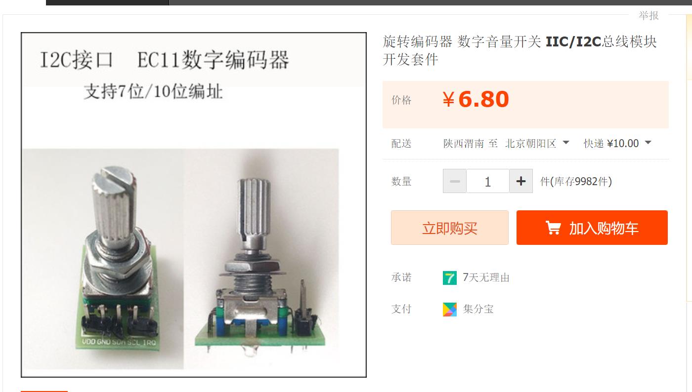
使用这种模块的话,只需要通过i2c读取就可以了,这样就不会漏掉旋转的步数
在验证过程中,忽略了一个很重要的事情,没有查找Linux源码中关于旋转编码器的说法
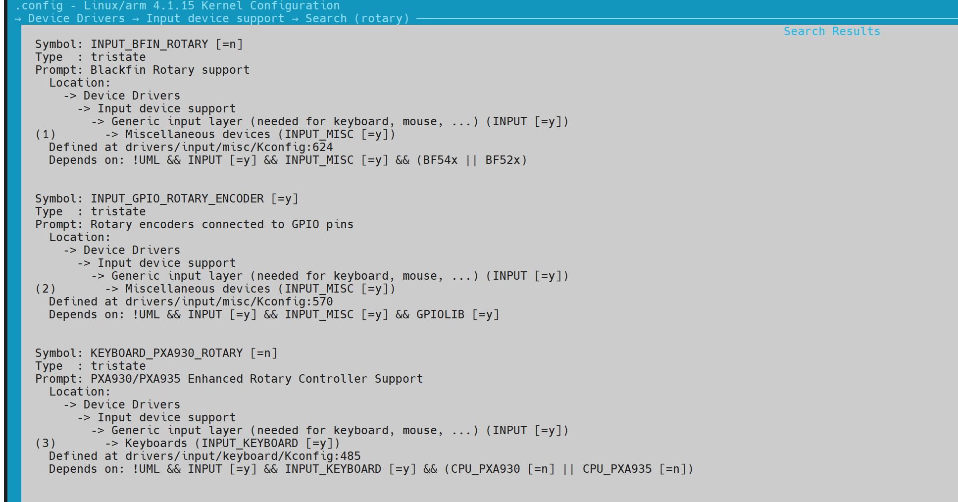
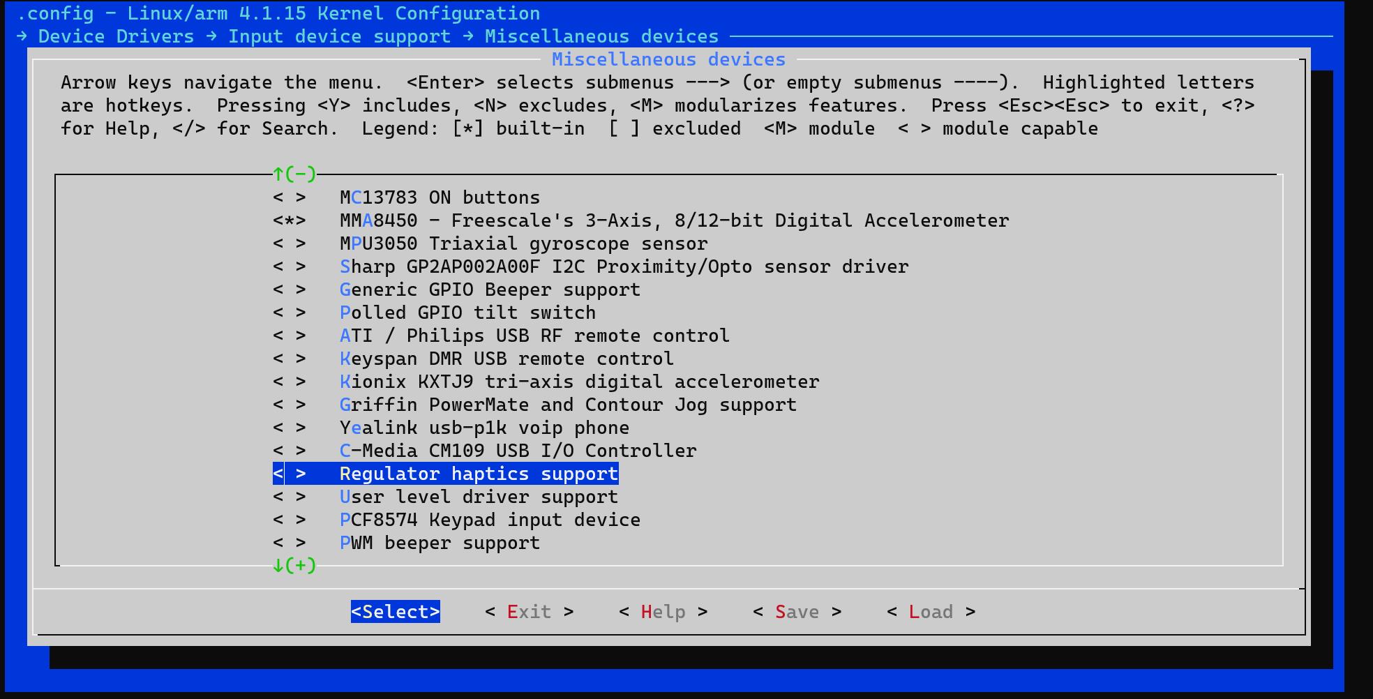
在make menuconfig中可以搜索到Rotary_Encoder相关的内核驱动,于是,顺着思路,在官网也可以看到相关的解释说明
现在,旋转编码器的软件方案朝着如何使用Linux内核源码驱动方向展开
虽然有了方向,但是无论是百度还是谷歌,都发现没有相关 的更加详细的资料,全部都是一些官方的资料,对于零基础的我还是需要走很多路
在之前,对于Linux驱动,只是通过模仿,写一些简单的驱动程序,没有涉及到添加一个官方驱动和修改设备树并且使用,如果这篇文章能够发出来,说明摸索到了一套完整的实现方法。
也算是全网首发旋转编码器内核源码驱动(包括设备树)的添加和使用吧
什么是Linux输入设备
老规矩,虽然基础可能在代码中我们接触不到,但是了解其工作原理,分层机制,才是通用的方法!对其他的驱动使用才能有启发作用。本文全程使用旋转编码器为例进行讲解。
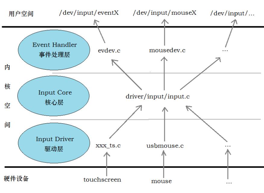
Linux输入设备总类繁杂,常见的包括有按键、键盘、触摸屏、鼠标、摇杆等等,他们本身就是字符设备,而linux内核将这些设备的共同性抽象出来,简化驱动开发建立了一个input子系统。子系统共分为三层,如图所示。
input 输入子系统
input输入子系统简介
输入设备(如按键,键盘,触摸屏,鼠标等)是典型的字符设备,其一般的工作机制是底层在按键,触摸等动作发生时产生一个中断(或驱动通过timer定时查询),然后cpu通过SPI,I2C或者外部存储器总线读取键值,坐标等数据,放一个缓冲区,字符设备驱动管理该缓冲区,而驱动的read()接口让用户可以读取键值,坐标等数据。
注意:这里有个关键,input输入子系统本质上也是内部使用中断对按键进行处理,所以对于旋转编码器EC11也是这样,跟之前自己使用中断去写一个杂项驱动是一样的本质,也是“中断”这个关键词,帮助我摸索到了使用的方法
这里插播之前的一篇文章,配合使用,对于rotary_encoder驱动源码理解更加顺畅
Linux嵌入式驱动开发14——中断的原理以及按键中断的实现(tasklet中断下文)
在Linux中,输入子系统是由输入子系统设备驱动层、输入子系统核心层(Input Core)和输入子系统事件处理层(Event Handler)组成。
其中设备驱动层提供对硬件各寄存器的读写访问和将底层硬件对用户输入访问的响应转换为标准的输入事件,再通过核心层提交给事件处理层;而核心层对下提供了设备驱动层的编程接口,对上又提供了事件处理层的编程接口;而事件处理层就为我们用户空间的应用程序提供了统一访问设备的接口和驱动层提交来的事件处理。所以这使得我们输入设备的驱动部分不在用关心对设备文件的操作,而是要关心对各硬件寄存器的操作和提交的输入事件。
- 驱动层和硬件相关,直接捕捉和获取硬件设备的数据信息等(包括触摸屏被按下、按下位置、鼠标移动、键盘按下等等),然后将数据信息报告到核心层。
- 核心层负责连接驱动层和事件处理层,设备驱动(device driver)和处理程序(handler)的注册需要通过核心层来完成,核心层接收来自驱动层的数据信息,并将数据信息选择对应的handler去处理,最终handler将数据复制到用户空间
输入子系统设备驱动层实现原理
在Linux中,Input设备用input_dev结构体描述,定义在input.h中。设备的驱动只需按照如下步骤就可实现了。
1).在驱动模块加载函数中设置Input设备支持input子系统的哪些事件;
2).将Input设备注册到input子系统中;
3).在Input设备发生输入操作时(如:键盘被按下/抬起、触摸屏被触摸/抬起/移动、鼠标被移动/单击/抬起时等),提交所发生的事件及对应的键值/坐标等状态。
input_dev、input_handler、input_handle
input_dev
struct input_dev {
      void *private;
      const char *name;
      const char *phys;
      const char *uniq;
      struct inBITS(KEY_MAX)];      //按键事件支持的子事件类型
      unsigned long relbit[NBITS(REL_MAX)];
      unsigned long absbit[NBITS(ABS_Mput_id id;      //与input_handler匹配用的id
      unsigned long evbit[NBITS(EV_MAX)];            //设备支持的事件类型
      unsigned long keybit[NAX)];      //绝对坐标事件支持的子事件类型
      unsigned long mscbit[NBITS(MSC_MAX)];
      unsigned long ledbit[NBITS(LED_MAX)];
      unsigned long sndbit[NBITS(SND_MAX)];
      unsigned long ffbit[NBITS(FF_MAX)];
      unsigned long swbit[NBITS(SW_MAX)];
      int ff_effects_max;
      unsigned int keycodemax;
      unsigned int keycodesize;
      void *keycode;
      unsigned int repeat_key;
      struct timer_list timer;
      struct pt_regs *regs;
      int state;
      int sync;
      int abs[ABS_MAX + 1];
      int rep[REP_MAX + 1];
      unsigned long key[NBITS(KEY_MAX)];
      unsigned long led[NBITS(LED_MAX)];
      unsigned long snd[NBITS(SND_MAX)];
      unsigned long sw[NBITS(SW_MAX)];
      int absmax[ABS_MAX + 1];      //绝对坐标事件的最大键值
      int absmin[ABS_MAX + 1];      //绝对坐标事件的最小键值
      int absfuzz[ABS_MAX + 1];
      int absflat[ABS_MAX + 1];
      int (*open)(struct input_dev *dev);
      void (*close)(struct input_dev *dev);
      int (*accept)(struct input_dev *dev, struct file *file);
      int (*flush)(struct input_dev *dev, struct file *file);
      int (*event)(struct input_dev *dev, unsigned int type, unsigned int code, int value);
      int (*upload_effect)(struct input_dev *dev, struct ff_effect *effect);
      int (*erase_effect)(struct input_dev *dev, int effect_id);
      struct input_handle *grab;      //当前占有该设备的handle
      struct mutex mutex;      /* serializes open and close operations */
      unsigned int users;            //打开该设备的用户量
      struct class_device cdev;
      struct device *dev;      /* will be removed soon */
      int dynalloc;      /* temporarily */
      struct list_head      h_list;      //该链表头用于链接该设备所关联的input_handle
      struct list_head      node;      //该链表头用于将设备链接到input_dev_list
};
Input_dev是一个很强大的结构体,它把所有的input设备(触摸屏、键盘、鼠标等)的信息都考虑到了,对于触摸屏来说只用到它里面的一部分而已,尤其是加粗的部分,注意该结构体中最后两行定义的两个list_head结构体,list_head在/linux/list.h中有定义,深入跟踪
struct list_head {
      struct list_head *next, *prev;
};
该结构体内部并没有定义数据而只定义了两个指向本身结构体的指针,预先说明一下:
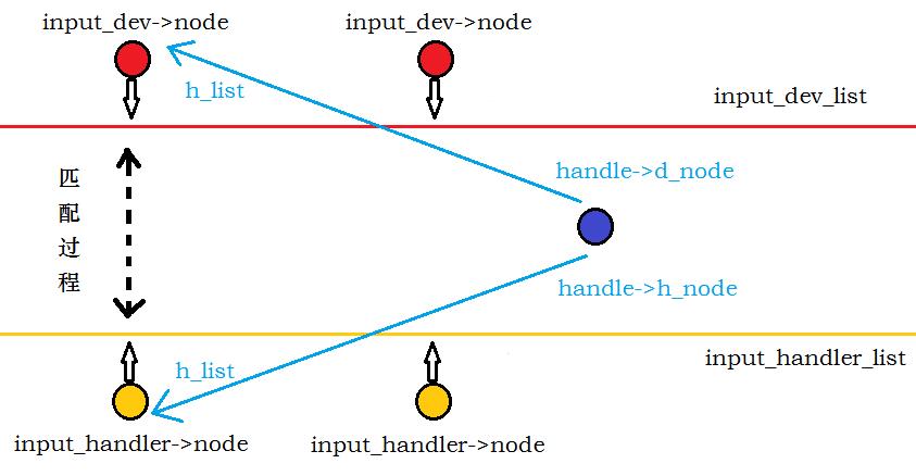
★ 所有的input device在注册后会加入一个input_dev_list(输入 设备链表)。
★ 所有的eventhandler在注册后会加入一个input_handler_list(输入处理程序链表),这里的list_head主要的作用是作为input_dev_list和input_handler_list的一个节点来保存地址。
Input_dev_list和input_handler_list之间的对应关系由input_handle结构体桥接,具体后面说明。
input_handler
struct input_handler {
      void *private;
      void (*event)(struct input_handle *handle, unsigned int type, unsigned int code, int value);
      struct input_handle* (*connect)(struct input_handler *handler, struct input_dev *dev, struct input_device_id *id);
      void (*disconnect)(struct input_handle *handle);
      const struct file_operations *fops;      //提供给用户对设备操作的函数指针
      int minor;
      char *name;
      struct input_device_id *id_table;      //与input_dev匹配用的id
      struct input_device_id *blacklist;      //标记的黑名单
      struct list_head      h_list;            //用于链接和该handler相关的handle
      struct list_head      node;            //用于将该handler链入input_handler_list
};
input_handler顾名思义,它是用来处理input_dev的一个结构体获取回来的数据,相关的处理函数在结构里内部都有定义,最后两行定义的list_head结构体作用同input_dev所定义的一样,这里不再说明。
注:input_device_id结构体在/linux/mod_devicetable.h中有定义
input_handle
struct input_handle {
      void *private;
      int open;      //记录设备打开次数
      char *name;
      struct input_dev *dev;      //指向所属的input_dev
      struct input_handler *handler;      //指向所属的input_handler
      struct list_head      d_node;            //用于链入所指向的input_dev的handle链表
      struct list_head      h_node;            //用于链入所指向的input_handler的handle链表
};
可以看到input_handle中拥有指向input_dev和input_handler的指针
★ 即input_handle是用来关联input_dev和input_handler。
为什么用input_handle来关联input_dev和input_handler而不将input_dev和input_handler直接对应呢?
因为一个device可以对应多个handler,而一个handler也可处理多个device。就如一个触摸屏设备可以对应event handler也可以对应tseve handler。
与软件设计有关的API函数
分配一个输入设备
Struct input_dev *input_allocate_device*(void);
注册一个输入设备
Int input_register_device(struct input_dev *dev);
驱动实现-事件支持
Set_bit告诉inout子系统它支持哪些事件
Set_bit(EV_KEY,button_dev.evbit)
Struct input_dev中有两个成员,一个是evbit;一个是keybit.分别用来表示设备所支持的事件类型和按键类型。
事件类型
Linux中输入设备的事件类型有(这里只列出了常用的一些,更多请看linux/input.h中):EV_SYN 0x00 同步事件
EV_KEY 0x01 按键事件
EV_REL 0x02 相对坐标
EV_ABS 0x03 绝对坐标
EV_MSC 0x04 其它
EV_LED 0x11 LED
EV_SND 0x12 声音
EV_REP 0x14 Repeat
EV_FF 0x15 力反馈
驱动实现-报告事件
Void input_event(struct input_dev *dev,unsigned int type,unsigned int code,int value);//报告指定type,code的输入事件
Void input_report_key(struct input_dev *dev,unsigned int code,int value);//报告键值
Void input_report_rel(struct input_dev *dev,unsigned int code,int value);//报告相对坐标
Void input_report_abs(struct input_dev *dev,unsigned int code,int value);//报告绝对坐标
Void input_sync(struct input_dev *dev);//报告同步事件
在触摸屏驱动设计中,一次坐标及按下状态的整个报告过程如下:
Input_report_abs(input_dev,ABS_X,x);//X坐标
Input_report_abs(input_dev,ABS_Y,y);//Y坐标
Input_report_abs(input_dev,ABS_PRESSURE,pres);//压力
input_sync(struct input_dev *dev);//同步
释放与注销设备
Void input_free_device(struct input_dev *dev);
Void input_unregister_device(struct input_dev *);
对于上面这些关键的结构体,目的不是吃透,而是熟悉,明白input输入子系统常用的结构体是哪些,哪些结构体出现意味着什么,有一个熟悉的感觉就可以了。
有了一定的input输入子系统的基础之后,我们来看官方的文档。进行后面是实践操作。
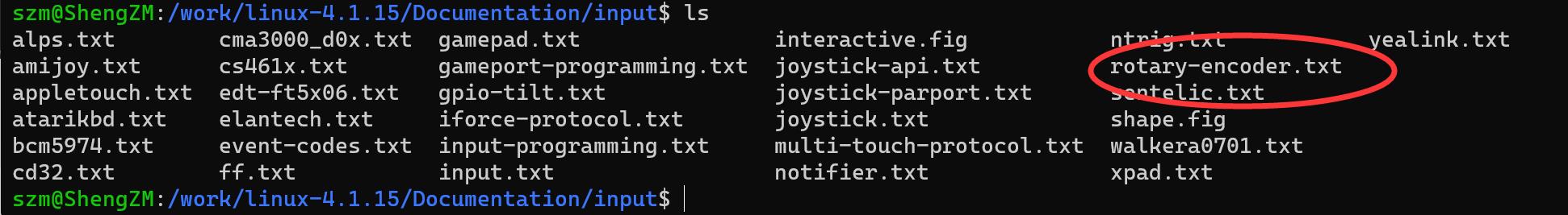
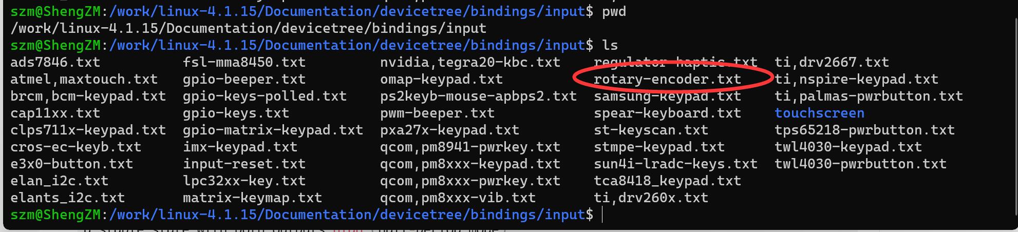
查看源码Documentation文档说明
对于一个驱动,最好的说明就是官方的文档,在Linux的Documentation文件夹中,我们直接搜索ratary就可以找到驱动的说明还有设备树的说明

目录如图所示:
驱动说明rotary-encoder - a generic driver for GPIO connected devices
对于这两个txt的说明文档,我也贴在了这里
rotary-encoder - a generic driver for GPIO connected devices
Daniel Mack <daniel@caiaq.de>, Feb 2009
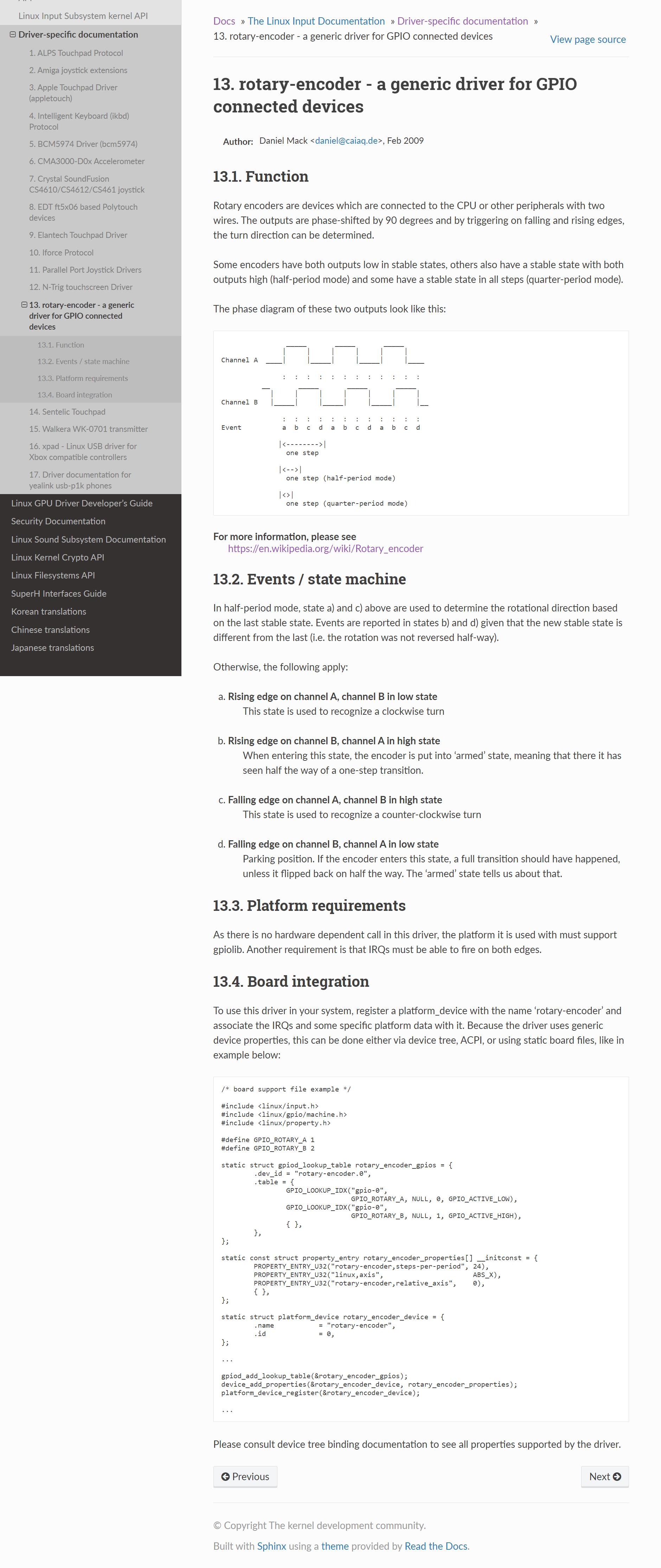
0. Function
-----------
Rotary encoders are devices which are connected to the CPU or other
peripherals with two wires. The outputs are phase-shifted by 90 degrees
and by triggering on falling and rising edges, the turn direction can
be determined.
Some encoders have both outputs low in stable states, whereas others also have
a stable state with both outputs high (half-period mode).
The phase diagram of these two outputs look like this:
_____ _____ _____
| | | | | |
Channel A ____| |_____| |_____| |____
: : : : : : : : : : : :
__ _____ _____ _____
| | | | | | |
Channel B |_____| |_____| |_____| |__
: : : : : : : : : : : :
Event a b c d a b c d a b c d
|<-------->|
one step
|<-->|
one step (half-period mode)
For more information, please see
http://en.wikipedia.org/wiki/Rotary_encoder
1. Events / state machine
-------------------------
In half-period mode, state a) and c) above are used to determine the
rotational direction based on the last stable state. Events are reported in
states b) and d) given that the new stable state is different from the last
(i.e. the rotation was not reversed half-way).
Otherwise, the following apply:
a) Rising edge on channel A, channel B in low state
This state is used to recognize a clockwise turn
b) Rising edge on channel B, channel A in high state
When entering this state, the encoder is put into 'armed' state,
meaning that there it has seen half the way of a one-step transition.
c) Falling edge on channel A, channel B in high state
This state is used to recognize a counter-clockwise turn
d) Falling edge on channel B, channel A in low state
Parking position. If the encoder enters this state, a full transition
should have happened, unless it flipped back on half the way. The
'armed' state tells us about that.
2. Platform requirements
------------------------
As there is no hardware dependent call in this driver, the platform it is
used with must support gpiolib. Another requirement is that IRQs must be
able to fire on both edges.
3. Board integration
--------------------
To use this driver in your system, register a platform_device with the
name 'rotary-encoder' and associate the IRQs and some specific platform
data with it.
struct rotary_encoder_platform_data is declared in
include/linux/rotary-encoder.h and needs to be filled with the number of
steps the encoder has and can carry information about externally inverted
signals (because of an inverting buffer or other reasons). The encoder
can be set up to deliver input information as either an absolute or relative
axes. For relative axes the input event returns +/-1 for each step. For
absolute axes the position of the encoder can either roll over between zero
and the number of steps or will clamp at the maximum and zero depending on
the configuration.
Because GPIO to IRQ mapping is platform specific, this information must
be given in separately to the driver. See the example below.
---------<snip>---------
/* board support file example */
#include <linux/input.h>
#include <linux/rotary_encoder.h>
#define GPIO_ROTARY_A 1
#define GPIO_ROTARY_B 2
static struct rotary_encoder_platform_data my_rotary_encoder_info = {
.steps = 24,
.axis = ABS_X,
.relative_axis = false,
.rollover = false,
.gpio_a = GPIO_ROTARY_A,
.gpio_b = GPIO_ROTARY_B,
.inverted_a = 0,
.inverted_b = 0,
.half_period = false,
};
static struct platform_device rotary_encoder_device = {
.name = "rotary-encoder",
.id = 0,
.dev = {
.platform_data = &my_rotary_encoder_info,
}
};
文档描述了内核源码的使用方法,这里的/* board support file example */给我造成了很大的迷惑,最后发现根本用不上,但是文档中的每一个字都要仔细的阅读,首先开头就说明了本驱动适用于通用GPIO,也就是说不需要特殊的硬件资源来进行实现。
第一节讲了旋转编码器的原理,先略过不是本章节的重点,第二节里面原文
2.Platform requirements
As there is no hardware dependent call in this driver, the platform it is used with must support gpiolib. Another requirement is that IRQs must be able to fire on both edges.
这段话是平台总线的申请条件,首先是必须要支持gpiolib,其次是GPIO需要支持中断的上升沿下降沿判断!
这两个条件其实还是比较好满足的,我的板子Linux源码版本是Linux4.1.15,选用的GPI也是普通GPIO口。
这里需要注意的是选择好IO之后,一定要去查看本IO能不能服用为普通GPIO,例如我要使用板子上的EIM_A16和EIM_A20口
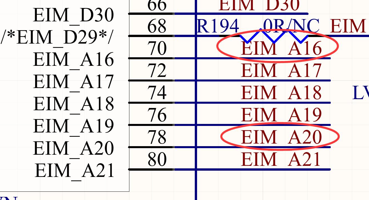
然后去GPIO子系统中去寻找,GPIO的定义部分在imx6q-pinfun.h文件中
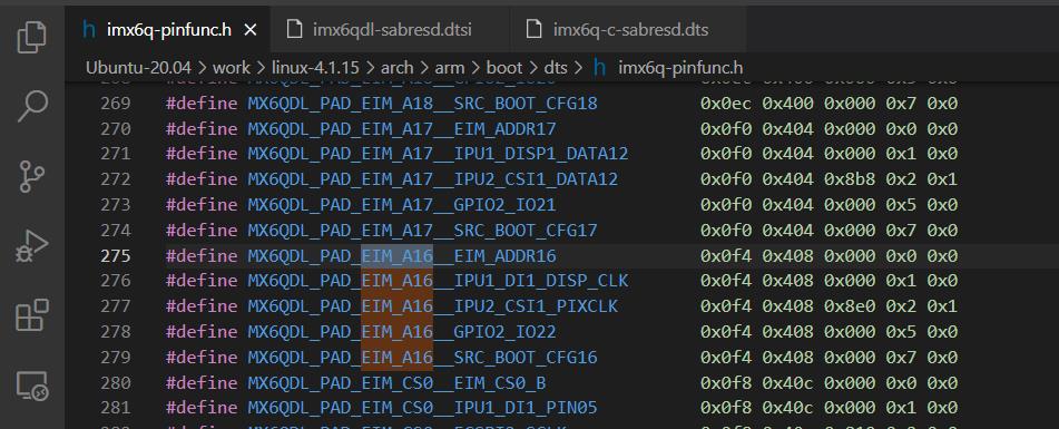
在这里的引脚定义中,可以看到可以服用为普通GPIO,也就是一会儿我们在设备中定义pinctrl子系统时候需要使用MX6QDL_PAD_EIM_A16__GPIO2_IO22来对应GPIO子系统的操作
第三节通过原文内容我们可以看到
To use this driver in your system, register a platform_device with the name ‘rotary-encoder’ and associate the IRQs and some specific platform data with it.
这里的重点是设备树节点的名称一定要是rotary-encoder,这样才可以和驱动中的match的驱动名字匹配上,以免driver和device匹配不上,还有就是关键的 associate the IRQs and some specific platform data with it,也就是要把中断匹配上,这里说明了设备树的添加方法和注意事项,接下来就是设备树。
设备树说明 Rotary encoder DT bindings
Rotary encoder DT bindings

Required properties:
- gpios: a spec for two GPIOs to be used

Optional properties:
- linux,axis: the input subsystem axis to map to this rotary encoder.
  Defaults to 0 (ABS_X / REL_X)
- rotary-encoder,steps: Number of steps in a full turnaround of the
  encoder. Only relevant for absolute axis. Defaults to 24 which is a
  typical value for such devices.
- rotary-encoder,relative-axis: register a relative axis rather than an
  absolute one. Relative axis will only generate +1/-1 events on the input
  device, hence no steps need to be passed.
- rotary-encoder,rollover: Automatic rollove when the rotary value becomes
  greater than the specified steps or smaller than 0. For absolute axis only.
- rotary-encoder,half-period: Makes the driver work on half-period mode.

See Documentation/input/rotary-encoder.txt for more information.

Example:

		rotary@0 {
			compatible = "rotary-encoder";
			gpios = <&gpio 19 1>, <&gpio 20 0>; /* GPIO19 is inverted */
			linux,axis = <0>; /* REL_X */
			rotary-encoder,relative-axis;
		};

		rotary@1 {
			compatible = "rotary-encoder";
			gpios = <&gpio 21 0>, <&gpio 22 0>;
			linux,axis = <1>; /* ABS_Y */
			rotary-encoder,steps = <24>;
			rotary-encoder,rollover;
		};
对于设备树代码的说明,也是很详细,每一项设置的说明都有
其中,ABS_X、REL_X 起初让我困惑不少,但是如果仔细看前面的input输入子系统介绍,REL_X 其实是输入设备的一种描述,相对轴,输出一个相对的值,对于旋转编码器来说也就是正转+1,反转-1
我探索过程中很大的困难都是设备树文件带来的,以及这个设备树例程的不熟悉
需要用到的GPIO为
MX6QDL_PAD_EIM_A16__GPIO2_IO22
MX6QDL_PAD_EIM_A20__GPIO2_IO18
通过文档,我们最直观得到的信息就是要首先在imx6qdl-saresd.dtsi文件,添加进来例程中的设备树,加进来设备的节点信息
对照例程设备树,首先要修改的就是gpios的写法
以上是关于Linux 输入设备调试详解(零基础开发)Rotary_Encoder旋转编码器模块(EC11)通用GPIO为例 挂载input输入子系统的主要内容,如果未能解决你的问题,请参考以下文章