UML state diagrams with draw.io
Posted Chuck Lu
tags:
篇首语:本文由小常识网(cha138.com)小编为大家整理,主要介绍了UML state diagrams with draw.io相关的知识,希望对你有一定的参考价值。
https://about.draw.io/uml-state-diagrams-with-draw-io/
State diagrams have been used in programming to describe the various possible states that a system can be in for decades. They also quickly show which states lead to each other, and what triggers a change of state.
Of course, you can use these diagrams for anything system or process that has various states – library books, a publishing process, even punishment and reward states for your kids. They are very similar to flow diagrams, but UML has a notation specifically for state diagrams, which they also call state machines or statecharts.
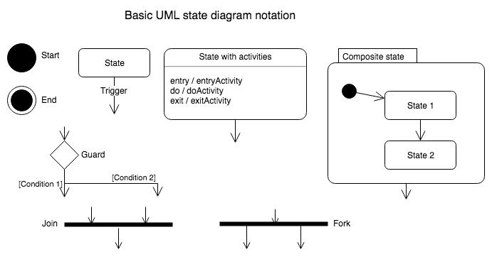
Components of UML state diagram
UML state diagrams use a notation that you may have already seen in our UML activity diagrams.
- Start state: A solid circle.
- End state: A solid circle with a ring around it.
- State: A rectangle with rounded corners, with the name of the action.
- Transition: Connector arrows with a label to indicate the trigger for that transition, if there is one.
- State with internal activities: A state with a horizontal line, and the actions listed in the bottom half.
- Composite state: A state with a horizontal line, and a nested state diagram (or link to another draw.io page) in the bottom half.
- Guards or conditions: A diamond.
- Fork: A thicker line with one transition incoming and two or more outgoing. 一个输入,多个输出
- Join: A thicker line with more than one transition incoming and only one outgoing. 多个输入,一个输出
Tip: UML 2 state diagrams use the clear black/white shapes, and UML 1 has yellow shapes with a red outline. I personally find UML 2 easier to read.

以上是关于UML state diagrams with draw.io的主要内容,如果未能解决你的问题,请参考以下文章
Python设计模式 - UML - 包图(Package Diagram)
Python设计模式 - UML - 定时图(Timing Diagram)