ESP32 VHCI架构实现BLE扫描设备
Posted Wireless_Link
tags:
篇首语:本文由小常识网(cha138.com)小编为大家整理,主要介绍了ESP32 VHCI架构实现BLE扫描设备相关的知识,希望对你有一定的参考价值。
零. 声明
本专栏文章我们会以连载的方式持续更新,本专栏计划更新内容如下:
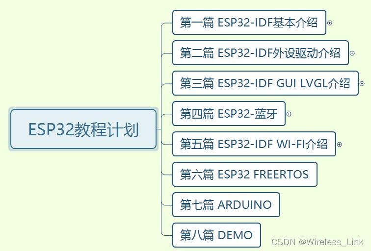
第一篇:ESP-IDF基本介绍,主要会涉及模组,芯片,开发板的介绍,环境搭建,程序编译下载,启动流程等一些基本的操作,让你对ESP-IDF开发有一个总体的认识,比我们后续学习打下基础!
第二篇:ESP32-IDF外设驱动介绍,主要会根据esp-idf现有的driver,提供各个外设的驱动,比如LED,OLED,SPI LCD,TOUCH,红外,Codec ic等等,在这一篇中,我们不仅仅来做外设驱动,还会对常用的外设总线做一个介绍,让大家知其然又知其所以然!
第三篇:目前比较火热的GUI LVGL介绍,主要会设计LVGL7.1,LVGL8的移植介绍,并且也会介绍各个组件,知道原理后,最后,我们会推出一款组态软件来构建我们的GUI,来提升我们的效率!
第四篇:ESP32-蓝牙,熟悉我的,应该都知道,我即使从事蓝牙协议栈的开发的,所以这个是我们独有的优势,在这一篇章,我们会提供不仅仅是蓝牙应用方法的知识,也会应用结合蓝牙底层协议栈的理论,让你彻底从上到下打通蓝牙任督二脉!
第五篇:Wi-Fi介绍,熟悉我的,应该也知道,我们也做过一款sdio wifi的驱动教程板子,所以在wifi这方面我们也是有独有的优势,在这一篇章,我们同样不仅仅提供Wi-Fi应用方面的知识,也会结合底层理论,让你对Wi-Fi有一个清晰的认知!
第六篇:FreeRTOS介绍,主要介绍下FreeRTOS各个功能(任务管理/消息队列/信号量/互斥量/事件/软件定时器/任务通知/内存管理/中断管理等)的使用以及运作机制。
第七篇:Arduino介绍,主要介绍ESP32 Arduino的基本操作(环境搭建,烧录,下载等开发流程),以及介绍下基于Arduino的外设,蓝牙,wifi的使用。
第八篇:Demo,此篇章是融会贯通以上章节,做一些综合性的demo,让你巩固以上篇章的同时,还能学到实际项目!!
另外,我们的教程包括但是不局限于以上篇章,为了给你一个更好的导航,以下信息尤其重要,请详细查看!!
------------------------------------------------------------------------------------------------------------------------------------------
蓝牙交流扣扣群:539357317
微信公众号↓↓↓↓↓↓↓↓↓↓↓↓↓↓↓↓↓↓↓↓↓↓↓↓↓↓↓↓↓↓↓↓↓↓↓↓↓↓↓↓↓↓↓↓↓↓↓↓↓↓↓↓↓↓↓↓↓↓↓↓↓↓↓↓↓↓↓↓↓↓↓↓↓↓↓
 ------------------------------------------------------------------------------------------------------------------------------------------
一. 整体介绍
此文章主要介绍基于ESP32 VHCI的架构实现BLE的扫描,也就是不使用默认的Host API,自己编写一部分代码来实现功能,具体ESP32的架构如下图所示:
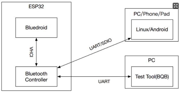
那我们做的事情是什么呢?我们相当于把默认的Host拿掉,也就是如图所示的bluedroid部分,写Host部分的广播实现

此文章算是熟悉一个VHCI的开发模式,不管对于默认的Host(Bluedroid/nimble)甚至自己移植进来一个Host都有很大的帮助,我就算起到一个抛砖引玉的作用吧!
二. menuconfig实现
我们虽然不用ESP32的默认Host,但是我们要用他默认的Controller,所以还是要配置一下的,一共三个地方需要特别留意一下,其他保持默认,如下图所示:
1.Bluetooth controller mode

2.HCI mode
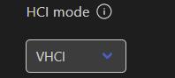
3.bluetooth Host

三. 程序实现
1.初始化NVS
/* Initialize NVS — it is used to store PHY calibration data */
esp_err_t ret = nvs_flash_init();
if (ret == ESP_ERR_NVS_NO_FREE_PAGES || ret == ESP_ERR_NVS_NEW_VERSION_FOUND)
    ESP_ERROR_CHECK(nvs_flash_erase());
    ret = nvs_flash_init();

ESP_ERROR_CHECK( ret );
这一段必须要加上,主要是用于存储PHY的信息,否则无法正常使用controller
2.初始化controller,注册Controller的callback函数实现
esp_bt_controller_config_t bt_cfg = BT_CONTROLLER_INIT_CONFIG_DEFAULT();

ret = esp_bt_controller_mem_release(ESP_BT_MODE_CLASSIC_BT);
if (ret)
    ESP_LOGI(TAG, "Bluetooth controller release classic bt memory failed: %s", esp_err_to_name(ret));
    return;


if ((ret = esp_bt_controller_init(&bt_cfg)) != ESP_OK)
    ESP_LOGI(TAG, "Bluetooth controller initialize failed: %s", esp_err_to_name(ret));
    return;


if ((ret = esp_bt_controller_enable(ESP_BT_MODE_BLE)) != ESP_OK)
    ESP_LOGI(TAG, "Bluetooth controller enable failed: %s", esp_err_to_name(ret));
    return;


......

esp_vhci_host_register_callback(&vhci_host_cb);
此段我们在介绍esp32 controller api的时候已经详细介绍,看API名字也知道主要在做什么事情,没什么难度,我们来看下注册给controller的callback的实现
/*
 * @brief: BT controller callback function, used to notify the upper layer that
 *         controller is ready to receive command
 */
static void controller_rcv_pkt_ready(void)

    ESP_LOGI(TAG, "controller rcv pkt ready");


/*
 * @brief: BT controller callback function to transfer data packet to
 *         the host
 */
static int host_rcv_pkt(uint8_t *data, uint16_t len)

    host_rcv_data_t send_data;
    uint8_t *data_pkt;
    /* Check second byte for HCI event. If event opcode is 0x0e, the event is
     * HCI Command Complete event. Sice we have recieved "0x0e" event, we can
     * check for byte 4 for command opcode and byte 6 for it's return status. */
    if (data[1] == 0x0e)
        if (data[6] == 0)
            ESP_LOGI(TAG, "Event opcode 0x%02x success.", data[4]);
         else
            ESP_LOGE(TAG, "Event opcode 0x%02x fail with reason: 0x%02x.", data[4], data[6]);
            return ESP_FAIL;


    data_pkt = (uint8_t *)malloc(sizeof(uint8_t) * len);
    if (data_pkt == NULL)
        ESP_LOGE(TAG, "Malloc data_pkt failed!");
        return ESP_FAIL;

    memcpy(data_pkt, data, len);
    send_data.q_data = data_pkt;
    send_data.q_data_len = len;
    if (xQueueSend(adv_queue, (void *)&send_data, ( TickType_t ) 0) != pdTRUE)
        ESP_LOGD(TAG, "Failed to enqueue advertising report. Queue full.");
        /* If data sent successfully, then free the pointer in `xQueueReceive'
         * after processing it. Or else if enqueue in not successful, free it
         * here. */
        free(data_pkt);

    return ESP_OK;


static esp_vhci_host_callback_t vhci_host_cb =
    controller_rcv_pkt_ready,
    host_rcv_pkt
;
此时收到数据,会通过消息队列把收到的数据发送出去,然后会有一个task专门接收消息队列的消息
void hci_evt_process(void *pvParameters)

    .....
    while (1)
        xQueueReceive(adv_queue, rcv_data, portMAX_DELAY);
        ....
我们只是列出来一个雏形,后续看懂了广播消息的格式,我们再来介绍下这个task解析广播包的具体代码
3.实现HCI 的扫描
while (continue_commands)
        if (continue_commands && esp_vhci_host_check_send_available())
            switch (cmd_cnt)
            case 0: hci_cmd_send_reset(); ++cmd_cnt; break;
            case 1: hci_cmd_send_set_evt_mask(); ++cmd_cnt; break;

            /* Send scan commands. */
            case 2: hci_cmd_send_ble_scan_params(); ++cmd_cnt; break;
            case 3: hci_cmd_send_ble_scan_start(); ++cmd_cnt; break;
            default: continue_commands = 0; break;

            ESP_LOGI(TAG, "BLE Advertise, cmd_sent: %d", cmd_cnt);

        vTaskDelay(1000 / portTICK_RATE_MS);
3.1 hci广播的流程
如果不考虑整个蓝牙Host的健壮性以及可用性,只考虑用ESP32 VHCI架构实现BLE广播功能,那么其实4个步骤就能实现,分别如下:
1) 发送HCI reset command
2) 发送set evt mask,如果这个不开启,那么收不到le meta event
3) 发送ble set scan param,也就是设置扫描的参数
4) 发送ble set scan start,也就是开启扫描
在后面的小节我们再一一介绍下每个command的格式以及作用!
3.2 hci command的格式
我们知道了步骤,并且知道了发送哪些command,但是command的格式是什么呢?那么这个算是一个比较大的话题,牵扯到蓝牙core spec hci章节的内容,我们本章本着应用文章,此部门我们简单的一笔带过,如果想彻底了解内部原理,那么我建议你看下这两篇文章:
蓝牙HCI command/event/acl/sco格式介绍_Wireless_Link的博客-CSDN博客
蓝牙传输介质Transport UART H4(RS232)介绍_Wireless_Link的博客-CSDN博客_蓝牙通过什么介质传输
以上两篇文章,分别介绍H4以及HCI的格式,好了,我们回归主题来介绍下HCI command的格式。
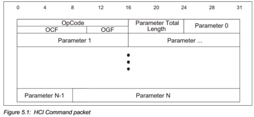
Opcode:每个命令被分配一个2字节的操作码(opcode),用来唯一地识别不同类型的命令,操作码(opcode)参数分为两个字段,称为操作码组字段(Opcode Group Field, OGF)和操作码命令字段(Opcode Command Field, OCF)。其中OGF占用高6bit字节,OCF占用低10bit字节。
一共有以下几组OGF:
1)Link Control commands, the OGF is defined as 0x01.链路控制OGF,也就是控制蓝牙芯片跟remote沟通的命令
2)Link Policy commands, the OGF is defined as 0x02,链路策略OGF,也就是写一些Policy,比如转换角色等
3)HCI Control and Baseband commands, the OGF is defined as 0x03,控制本地芯片跟基带的OGF。比如reset本地芯片等。
4)Informational Parameters commands, the OGF is defined as 0x04。读取信息的OGF,比如读取本地芯片的LMP版本呢,支持的command,蓝牙地址等,
5)status parameters commands, the OGF is defined as 0x05,状态参数OGF,比如读取RSSI等。
6)Testing commands, the OGF is defined as 0x06,测试命令的OGF,比如让芯片进入测试模式(DUT,device under test)
7)LE Controller commands, the OGF code is defined as 0x08,BLE 的comand
8)vendor-specific debug commands,the OGF code is defined as 0x3F,此部分是vendor定义的,也就是芯片厂商为了扩展core文档的HCI command定义
OCF众多,在每个OGF下都有一堆的OCF定义
Parameter Total Length:后续参数的长度
Parameter:每个command的para不同
3.3 hci event的格式
HCI event是蓝牙芯片发送给协议栈的事件。HCI事件包的格式如下图所示:
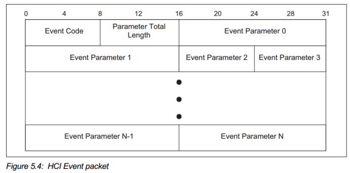
Event code:唯一event编码,在后续的小节会介绍(是固定的)
Parameter Total Length:后续参数的长度
Parameter:event参数。
3.4 hci reset命令
hci command的命令如下:
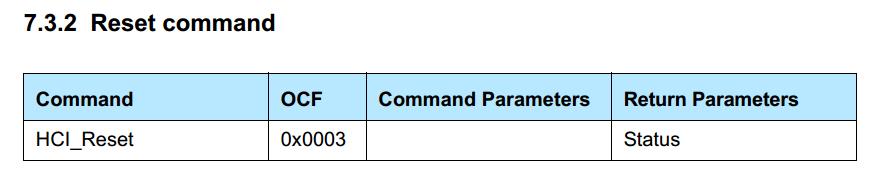
OGF是0x03,OCF是0x03
hci reset作用如下:
The HCI_Reset command willreset the Controller and the Link Manager on the BR/EDR Controller or the Link Layer on an LE Controller. If the Controller supports both BR/EDR and LEthen the HCI_Reset command shall reset the Link Manager, Baseband and Link Layer. The HCI_Reset command shall not affect the used HCI transport layer since the HCI transport layers may have reset mechanisms of their own. After the reset is completed, the current operational state will be lost, the Controller will enter standby mode and the Controller will automatically revert to the default values for the parameters for which default values are defined in the specification.
Note: The HCI_Reset command will not necessarily perform a hardware reset. This is implementation defined.
The Host shall not send additional HCI commands before the HCI_Command_Complete event related to the HCI_Reset command has been received。
函数实现如下:
/* HCI Command Opcode group Field (OGF) */
#define HCI_GRP_HOST_CONT_BASEBAND_CMDS (0x03 << 10) /* 0x0C00 */
#define HCI_GRP_BLE_CMDS (0x08 << 10)
/* HCI Command Opcode Command Field (OCF) */
#define HCI_RESET (0x0003 | HCI_GRP_HOST_CONT_BASEBAND_CMDS)
uint16_t make_cmd_reset(uint8_t *buf)
UINT8_TO_STREAM (buf, H4_TYPE_COMMAND);
UINT16_TO_STREAM (buf, HCI_RESET);
UINT8_TO_STREAM (buf, 0);
return HCI_H4_CMD_PREAMBLE_SIZE;
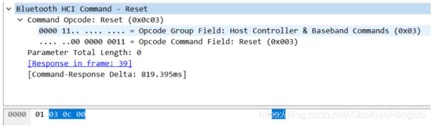
static void hci_cmd_send_reset(void)
uint16_t sz = make_cmd_reset (hci_cmd_buf);
esp_vhci_host_send_packet(hci_cmd_buf, sz);
组成的数据格式是:0x01 ,0x03 0x0c 0x00
3.5 hci set event mask命令
hci command的格式如下:
OGF=0x03,OCF=0x01
我们来看下这个command的格式:
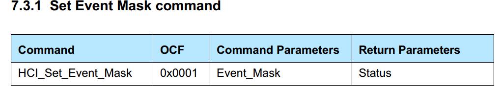
Event_Mask:事件掩码,也就是决定哪些消息可以从controller上报到host,有以下消息
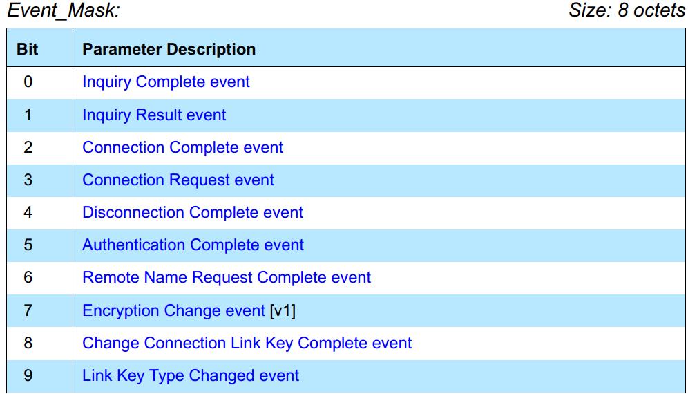
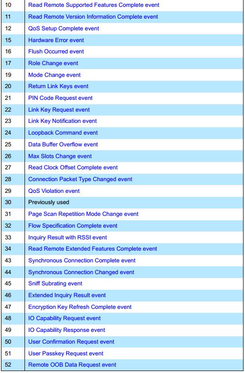
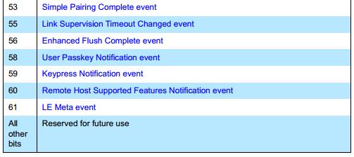
整个实现的代码如下:
uint16_t make_cmd_set_evt_mask (uint8_t *buf, uint8_t *evt_mask)
UINT8_TO_STREAM (buf, H4_TYPE_COMMAND);
UINT16_TO_STREAM (buf, HCI_SET_EVT_MASK);
UINT8_TO_STREAM (buf, HCIC_PARAM_SIZE_SET_EVENT_MASK);
ARRAY_TO_STREAM(buf, evt_mask, HCIC_PARAM_SIZE_SET_EVENT_MASK);
return HCI_H4_CMD_PREAMBLE_SIZE + HCIC_PARAM_SIZE_SET_EVENT_MASK;
static void hci_cmd_send_set_evt_mask(void)
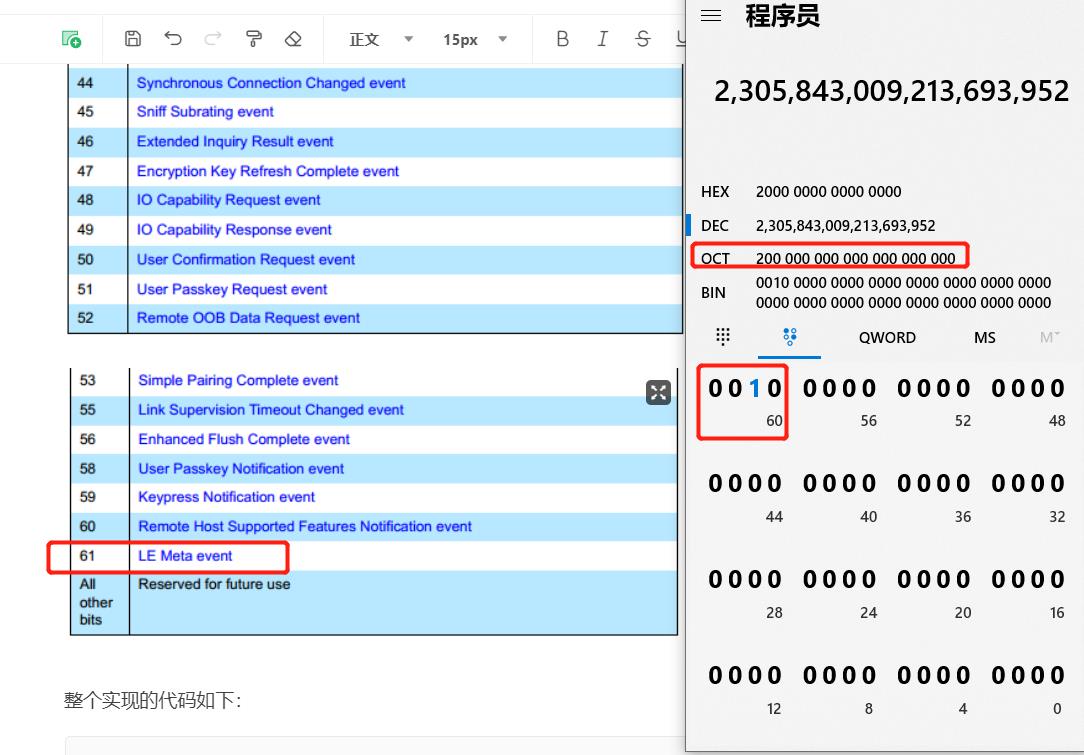
/* Set bit 61 in event mask to enable LE Meta events. */
uint8_t evt_mask[8] = 0x00, 0x00, 0x00, 0x00, 0x00, 0x00, 0x00, 0x20;
uint16_t sz = make_cmd_set_evt_mask(hci_cmd_buf, evt_mask);
esp_vhci_host_send_packet(hci_cmd_buf, sz);
从代码中可以得知开启了le meta的event
3.6 ble set scan param命令
hci command的格式如下:
OGF=0x08,OCF=0x0B
我们来看下这个command的格式:
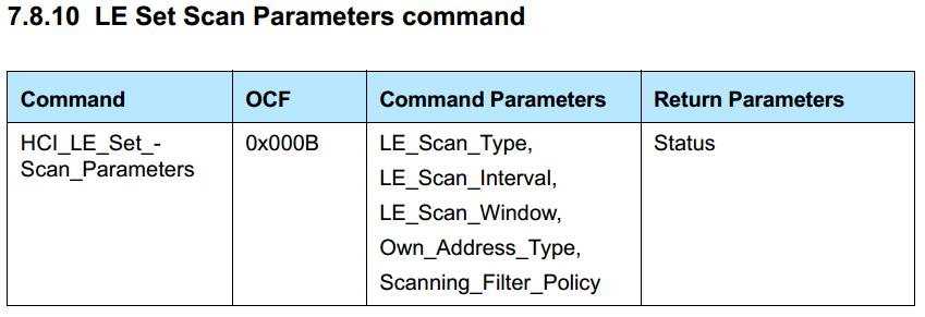
LE_Scan_Type:分主动扫描跟被动扫描
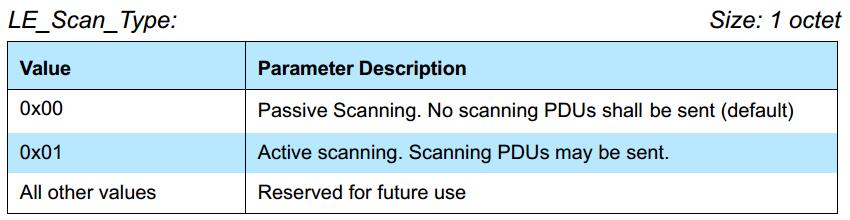
区别主要有几个:
被动扫描仅仅接受广播包,不会发起扫描请求
主动扫描接受广播包后悔发送扫描请求给处于广播态的设备,来获取额外的广播数据
一般被动扫描用于确定从机不会发送扫描响应,只会发送31byte的广播数据,而主动扫描用于不确定从机是否有额外的数据,所以要额外发起扫描请求来接受更多的广播的数据
注意:主动扫描的扫描请求以及扫描响应也是广播封包
LE_Scan_Window跟LE_Scan_Interval:扫描窗口跟扫描间隔

效果如图:这个就决定了扫描的占空比~

uint16_t make_cmd_ble_set_scan_params (uint8_t *buf, uint8_t scan_type,
                                       uint16_t scan_interval, uint16_t scan_window,
                                       uint8_t own_addr_type, uint8_t filter_policy)

    UINT8_TO_STREAM (buf, H4_TYPE_COMMAND);
    UINT16_TO_STREAM (buf, HCI_BLE_WRITE_SCAN_PARAM);
    UINT8_TO_STREAM  (buf, HCIC_PARAM_SIZE_BLE_WRITE_SCAN_PARAM);
    UINT8_TO_STREAM (buf, scan_type);
    UINT16_TO_STREAM (buf, scan_interval);
    UINT16_TO_STREAM (buf, scan_window);
    UINT8_TO_STREAM (buf, own_addr_type);
    UINT8_TO_STREAM (buf, filter_policy);
    return HCI_H4_CMD_PREAMBLE_SIZE + HCIC_PARAM_SIZE_BLE_WRITE_SCAN_PARAM;

static void hci_cmd_send_ble_scan_params(void)

    /* Set scan type to 0x01 for active scanning and 0x00 for passive scanning. */
    uint8_t scan_type = 0x01;

    /* Scan window and Scan interval are set in terms of number of slots. Each slot is of 625 microseconds. */
    uint16_t scan_interval = 0x50; /* 50 ms */
    uint16_t scan_window = 0x30; /* 30 ms */

    uint8_t own_addr_type = 0x00; /* Public Device Address (default). */
    uint8_t filter_policy = 0x00; /* Accept all packets excpet directed advertising packets (default). */
    uint16_t sz = make_cmd_ble_set_scan_params(hci_cmd_buf, scan_type, scan_interval, scan_window, own_addr_type, filter_policy);
    esp_vhci_host_send_packet(hci_cmd_buf, sz);
3.7 hci send ble scan start命令
hci command的格式如下:
OGF=0x08,OCF=0x0c
我们来看下这个command的格式:
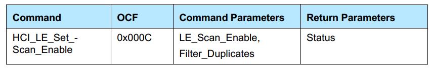
LE_Scan_Enable:开始或者停止扫描

Filter_Duplicates:是否过滤重复的内容
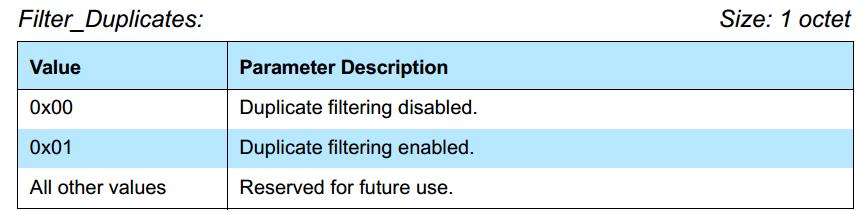
代码如下:
static void hci_cmd_send_ble_scan_start(void)

    uint8_t scan_enable = 0x01; /* Scanning enabled. */
    uint8_t filter_duplicates = 0x00; /* Duplicate filtering disabled. */
    uint16_t sz = make_cmd_ble_set_scan_enable(hci_cmd_buf, scan_enable, filter_duplicates);
    esp_vhci_host_send_packet(hci_cmd_buf, sz);
    ESP_LOGI(TAG, "BLE Scanning started..");

uint16_t make_cmd_ble_set_scan_enable (uint8_t *buf, uint8_t scan_enable,
                                       uint8_t filter_duplicates)

    UINT8_TO_STREAM (buf, H4_TYPE_COMMAND);
    UINT16_TO_STREAM (buf, HCI_BLE_WRITE_SCAN_ENABLE);
    UINT8_TO_STREAM  (buf, HCIC_PARAM_SIZE_BLE_WRITE_SCAN_ENABLE);
    UINT8_TO_STREAM (buf, scan_enable);
    UINT8_TO_STREAM (buf, filter_duplicates);
    return HCI_H4_CMD_PREAMBLE_SIZE + HCIC_PARAM_SIZE_BLE_WRITE_SCAN_ENABLE;
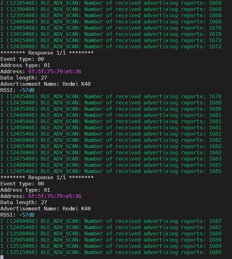
3.8 解析扫描到的设备信息
收到的是这个event,具体原理可以看下我这篇文章
低功耗蓝牙搜索广播的实现流流程介绍 /BLE scan flow ----- 蓝牙低功耗协议栈_Wireless_Link的博客-CSDN博客
四.程序效果
以上是关于ESP32 VHCI架构实现BLE扫描设备的主要内容,如果未能解决你的问题,请参考以下文章