基于ubuntu环境,搭建Arduino+ESP32+MPU6050验证系统,并利用Processing仿真
Posted pocean2012
tags:
篇首语:本文由小常识网(cha138.com)小编为大家整理,主要介绍了基于ubuntu环境,搭建Arduino+ESP32+MPU6050验证系统,并利用Processing仿真相关的知识,希望对你有一定的参考价值。
具体姿态解算和原理性验证,姿态反馈控制另文描述,本文只针对基本验证环境搭建。
1. 建立基于Arduino的ESP32开发环境
原来用micro和promini都做了环境,但是隔了一段时间居然串口烧录把板子搞挂了,pro mini串口烧录也老出问题,先放一放,手上刚好有EPS32的开发板,毕竟ESP32带了wifi和蓝牙,也有多个串口,资源够用,也方便数据传输,用来读取MPU6050开发板的数据做原理性验证绰绰有余了。
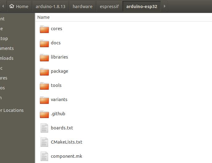
Arduino直接下ESP32的包
GitHub - pocean2001/arduino-esp32: Arduino core for the ESP32
在Arduino下建立hardware/espressif目录,下载后解压,可以把目录名改为esp32
记得要运行工具
(base) hy@hy-Mi-Gaming-Laptop-15-6:~/arduino-1.8.13/hardware/espressif/arduino-esp32/tools$ python get.py
System: Linux, Bits: 64, Info: Linux-5.4.0-65-generic-x86_64-with-glibc2.10
Platform: x86_64-pc-linux-gnu
Downloading xtensa-esp32-elf-linux64-1.22.0-80-g6c4433a-5.2.0.tar.gz ...
Done
Extracting xtensa-esp32-elf-linux64-1.22.0-80-g6c4433a-5.2.0.tar.gz ...
Downloading esptool-2.6.1-linux.tar.gz ...
Done
Extracting esptool-2.6.1-linux.tar.gz ...
Downloading mkspiffs-0.2.3-arduino-esp32-linux64.tar.gz ...
Done
Extracting mkspiffs-0.2.3-arduino-esp32-linux64.tar.gz ...
Renaming mkspiffs-0.2.3-arduino-esp32-linux64 to mkspiffs ...
Platform Tools Installed
打开Arduino,选择板子和端口,此时需要把串口的权限开一下
sudo chmod 777 /dev/ttyUSB0
2. 下载MPU6050的开发库
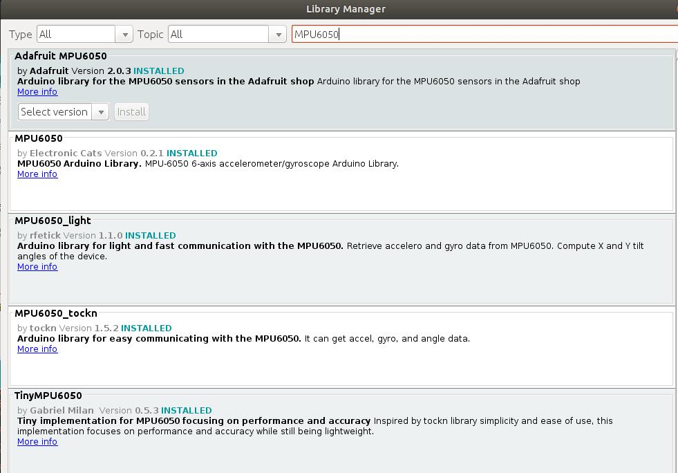
能下的都搞下来玩一遍
3. 修改接口,测试传感器数据输出
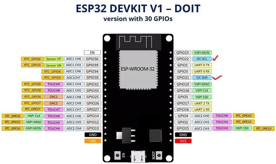
用的esp32的引脚图
例子MPU6050_DMP6有多种数据输出形式,就用它,要改几个地方。
用wire.h库做驱动
#include "Wire.h"
定义中断引脚
#define INTERRUPT_PIN 5
定义I2C接口引脚scl/sda
Wire.begin(4,15);
这一段宏定义定义数据输出方式:
// uncomment "OUTPUT_READABLE_QUATERNION" if you want to see the actual
// quaternion components in a [w, x, y, z] format (not best for parsing
// on a remote host such as Processing or something though)
#define OUTPUT_READABLE_QUATERNION
// uncomment "OUTPUT_READABLE_EULER" if you want to see Euler angles
// (in degrees) calculated from the quaternions coming from the FIFO.
// Note that Euler angles suffer from gimbal lock (for more info, see
// http://en.wikipedia.org/wiki/Gimbal_lock)
//#define OUTPUT_READABLE_EULER
// uncomment "OUTPUT_READABLE_YAWPITCHROLL" if you want to see the yaw/
// pitch/roll angles (in degrees) calculated from the quaternions coming
// from the FIFO. Note this also requires gravity vector calculations.
// Also note that yaw/pitch/roll angles suffer from gimbal lock (for
// more info, see: http://en.wikipedia.org/wiki/Gimbal_lock)
//#define OUTPUT_READABLE_YAWPITCHROLL
// uncomment "OUTPUT_READABLE_REALACCEL" if you want to see acceleration
// components with gravity removed. This acceleration reference frame is
// not compensated for orientation, so +X is always +X according to the
// sensor, just without the effects of gravity. If you want acceleration
// compensated for orientation, us OUTPUT_READABLE_WORLDACCEL instead.
//#define OUTPUT_READABLE_REALACCEL
// uncomment "OUTPUT_READABLE_WORLDACCEL" if you want to see acceleration
// components with gravity removed and adjusted for the world frame of
// reference (yaw is relative to initial orientation, since no magnetometer
// is present in this case). Could be quite handy in some cases.
//#define OUTPUT_READABLE_WORLDACCEL
// uncomment "OUTPUT_TEAPOT" if you want output that matches the
// format used for the InvenSense teapot demo
//#define OUTPUT_TEAPOT
对应下面的数据处理输出:
#ifdef OUTPUT_READABLE_QUATERNION
// display quaternion values in easy matrix form: w x y z
mpu.dmpGetQuaternion(&q, fifoBuffer);
Serial.print("quat\\t");
Serial.print(q.w);
Serial.print("\\t");
Serial.print(q.x);
Serial.print("\\t");
Serial.print(q.y);
Serial.print("\\t");
Serial.println(q.z);
#endif
#ifdef OUTPUT_READABLE_EULER
// display Euler angles in degrees
mpu.dmpGetQuaternion(&q, fifoBuffer);
mpu.dmpGetEuler(euler, &q);
Serial.print("euler\\t");
Serial.print(euler[0] * 180/M_PI);
Serial.print("\\t");
Serial.print(euler[1] * 180/M_PI);
Serial.print("\\t");
Serial.println(euler[2] * 180/M_PI);
#endif
#ifdef OUTPUT_READABLE_YAWPITCHROLL
// display Euler angles in degrees
mpu.dmpGetQuaternion(&q, fifoBuffer);
mpu.dmpGetGravity(&gravity, &q);
mpu.dmpGetYawPitchRoll(ypr, &q, &gravity);
Serial.print("ypr\\t");
Serial.print(ypr[0] * 180/M_PI);
Serial.print("\\t");
Serial.print(ypr[1] * 180/M_PI);
Serial.print("\\t");
Serial.println(ypr[2] * 180/M_PI);
#endif
#ifdef OUTPUT_READABLE_REALACCEL
// display real acceleration, adjusted to remove gravity
mpu.dmpGetQuaternion(&q, fifoBuffer);
mpu.dmpGetAccel(&aa, fifoBuffer);
mpu.dmpGetGravity(&gravity, &q);
mpu.dmpGetLinearAccel(&aaReal, &aa, &gravity);
Serial.print("areal\\t");
Serial.print(aaReal.x);
Serial.print("\\t");
Serial.print(aaReal.y);
Serial.print("\\t");
Serial.println(aaReal.z);
#endif
#ifdef OUTPUT_READABLE_WORLDACCEL
// display initial world-frame acceleration, adjusted to remove gravity
// and rotated based on known orientation from quaternion
mpu.dmpGetQuaternion(&q, fifoBuffer);
mpu.dmpGetAccel(&aa, fifoBuffer);
mpu.dmpGetGravity(&gravity, &q);
mpu.dmpGetLinearAccel(&aaReal, &aa, &gravity);
mpu.dmpGetLinearAccelInWorld(&aaWorld, &aaReal, &q);
Serial.print("aworld\\t");
Serial.print(aaWorld.x);
Serial.print("\\t");
Serial.print(aaWorld.y);
Serial.print("\\t");
Serial.println(aaWorld.z);
#endif
#ifdef OUTPUT_TEAPOT
// display quaternion values in InvenSense Teapot demo format:
teapotPacket[2] = fifoBuffer[0];
teapotPacket[3] = fifoBuffer[1];
teapotPacket[4] = fifoBuffer[4];
teapotPacket[5] = fifoBuffer[5];
teapotPacket[6] = fifoBuffer[8];
teapotPacket[7] = fifoBuffer[9];
teapotPacket[8] = fifoBuffer[12];
teapotPacket[9] = fifoBuffer[13];
Serial.write(teapotPacket, 14);
teapotPacket[11]++; // packetCount, loops at 0xFF on purpose
#endif
TEAPOT格式下的输出输出格式:
// packet structure for InvenSense teapot demo
uint8_t teapotPacket[14] = '$', 0x02, 0,0, 0,0, 0,0, 0,0, 0x00, 0x00, '\\r', '\\n' ;
在processing仿真读取的数据就是teapot格式
4. processing环境下读取数据并建立仿真模型
processing的安装直接上官网,速度还可以,基于java或者基于python,也可以下载例程由浅入深学习,此处不展开。
其实不用下载额外的库,直接用刚才arduino的mpu6050库配套的例程就可以,路径
/home/hy/Arduino/libraries/MPU6050/examples/MPU6050_DMP6/Processing/MPUTeapot/MPUTeapot.pde
运行结果
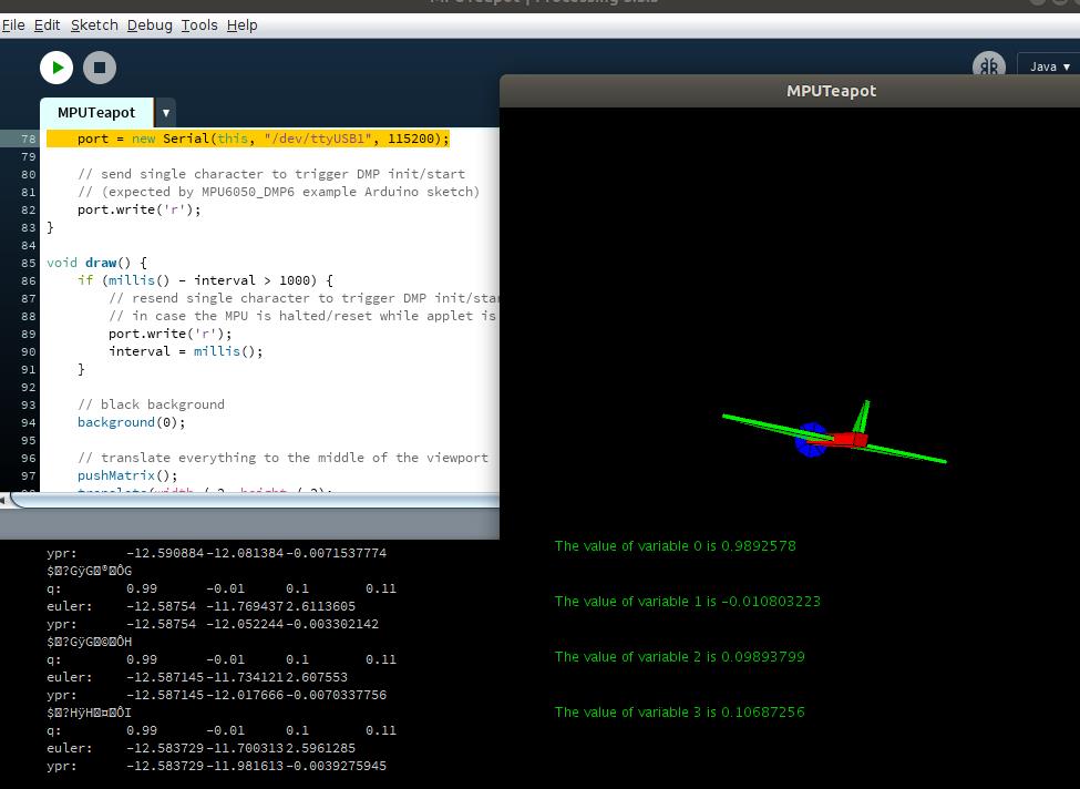
数据还是会有漂移 ,是精度问题?还是需要引入卡尔曼滤波? 下一步考虑
下面是arduino和processing完整代码
#include "I2Cdev.h"

#include "MPU6050_6Axis_MotionApps20.h"
//#include "MPU6050.h" // not necessary if using MotionApps include file

// Arduino Wire library is required if I2Cdev I2CDEV_ARDUINO_WIRE implementation
// is used in I2Cdev.h
//#if I2CDEV_IMPLEMENTATION == I2CDEV_ARDUINO_WIRE
 #include "Wire.h"
//#endif

// class default I2C address is 0x68
// specific I2C addresses may be passed as a parameter here
// AD0 low = 0x68 (default for SparkFun breakout and InvenSense evaluation board)
// AD0 high = 0x69
MPU6050 mpu;
//MPU6050 mpu(0x69); // <-- use for AD0 high

/* =========================================================================
   NOTE: In addition to connection 3.3v, GND, SDA, and SCL, this sketch
   depends on the MPU-6050's INT pin being connected to the Arduino's
   external interrupt #0 pin. On the Arduino Uno and Mega 2560, this is
   digital I/O pin 2.
 * ========================================================================= */

/* =========================================================================
   NOTE: Arduino v1.0.1 with the Leonardo board generates a compile error
   when using Serial.write(buf, len). The Teapot output uses this method.
   The solution requires a modification to the Arduino USBAPI.h file, which
   is fortunately simple, but annoying. This will be fixed in the next IDE
   release. For more info, see these links:

   http://arduino.cc/forum/index.php/topic,109987.0.html
   http://code.google.com/p/arduino/issues/detail?id=958
 * ========================================================================= */


// uncomment "OUTPUT_READABLE_QUATERNION" if you want to see the actual
// quaternion components in a [w, x, y, z] format (not best for parsing
// on a remote host such as Processing or something though)
//#define OUTPUT_READABLE_QUATERNION

// uncomment "OUTPUT_READABLE_EULER" if you want to see Euler angles
// (in degrees) calculated from the quaternions coming from the FIFO.
// Note that Euler angles suffer from gimbal lock (for more info, see
// http://en.wikipedia.org/wiki/Gimbal_lock)
//#define OUTPUT_READABLE_EULER

// uncomment "OUTPUT_READABLE_YAWPITCHROLL" if you want to see the yaw/
// pitch/roll angles (in degrees) calculated from the quaternions coming
// from the FIFO. Note this also requires gravity vector calculations.
// Also note that yaw/pitch/roll angles suffer from gimbal lock (for
// more info, see: http://en.wikipedia.org/wiki/Gimbal_lock)
//#define OUTPUT_READABLE_YAWPITCHROLL

// uncomment "OUTPUT_READABLE_REALACCEL" if you want to see acceleration
// components with gravity removed. This acceleration reference frame is
// not compensated for orientation, so +X is always +X according to the
// sensor, just without the effects of gravity. If you want acceleration
// compensated for orientation, us OUTPUT_READABLE_WORLDACCEL instead.
//#define OUTPUT_READABLE_REALACCEL

// uncomment "OUTPUT_READABLE_WORLDACCEL" if you want to see acceleration
// components with gravity removed and adjusted for the world frame of
// reference (yaw is relative to initial orientation, since no magnetometer
// is present in this case). Could be quite handy in some cases.
//#define OUTPUT_READABLE_WORLDACCEL

// uncomment "OUTPUT_TEAPOT" if you want output that matches the
// format used for the InvenSense teapot demo
#define OUTPUT_TEAPOT


#define INTERRUPT_PIN 5  // use pin 2 on Arduino Uno & most boards
#define LED_PIN 2 // (Arduino is 13, Teensy is 11, Teensy++ is 6)
bool blinkState = false;

// MPU control/status vars
bool dmpReady = false;  // set true if DMP init was successful
uint8_t mpuIntStatus;   // holds actual interrupt status byte from MPU
uint8_t devStatus;      // return status after each device operation (0 = success, !0 = error)
uint16_t packetSize;    // expected DMP packet size (default is 42 bytes)
uint16_t fifoCount;     // count of all bytes currently in FIFO
uint8_t fifoBuffer[64]; // FIFO storage buffer

// orientation/motion vars
Quaternion q;           // [w, x, y, z]         quaternion container
VectorInt16 aa;         // [x, y, z]            accel sensor measurements
VectorInt16 aaReal;     // [x, y, z]            gravity-free accel sensor measurements
VectorInt16 aaWorld;    // [x, y, z]            world-frame accel sensor measurements
VectorFloat gravity;    // [x, y, z]            gravity vector
float euler[3];         // [psi, theta, phi]    Euler angle container
float ypr[3];           // [yaw, pitch, roll]   yaw/pitch/roll container and gravity vector

// packet structure for InvenSense teapot demo
uint8_t teapotPacket[14] =  '$', 0x02, 0,0, 0,0, 0,0, 0,0, 0x00, 0x00, '\\r', '\\n' ;


// ================================================================
// ===               INTERRUPT DETECTION ROUTINE                ===
// ================================================================

volatile bool mpuInterrupt = false;     // indicates whether MPU interrupt pin has gone high
void dmpDataReady()
    mpuInterrupt = true;


// ================================================================
// ===                      INITIAL SETUP                       ===
// ================================================================

void setup()
    // join I2C bus (I2Cdev library doesn't do this automatically)
    //#if I2CDEV_IMPLEMENTATION == I2CDEV_ARDUINO_WIRE
        Wire.begin(4,15);
        Wire.setClock(400000); // 400kHz I2C clock. Comment this line if having compilation difficulties
   // #elif I2CDEV_IMPLEMENTATION == I2CDEV_BUILTIN_FASTWIRE
   //     Fastwire::setup(400, true);
   // #endif

    // initialize serial communication
    // (115200 chosen because it is required for Teapot Demo output, but it's
    // really up to you depending on your project)
    Serial.begin(115200);
    while (!Serial); // wait for Leonardo enumeration, others continue immediately

    // NOTE: 8MHz or slower host processors, like the Teensy @ 3.3V or Arduino
    // Pro Mini running at 3.3V, cannot handle this baud rate reliably due to
    // the baud timing being too misaligned with processor ticks. You must use
    // 38400 or slower in these cases, or use some kind of external separate
    // crystal solution for the UART timer.

    // initialize device
    Serial.println(F("Initializing I2C devices..."));
    mpu.initialize();
    pinMode(INTERRUPT_PIN, INPUT);

    // verify connection
    Serial.println(F("Testing device connections..."));
    Serial.println(mpu.testConnection() ? F("MPU6050 connection successful") : F("MPU6050 connection failed"));

    // wait for ready
    Serial.println(F("\\nSend any character to begin DMP programming and demo: "));
    while (Serial.available() && Serial.read()); // empty buffer
    while (!Serial.available());                 // wait for data
    while (Serial.available() && Serial.read()); // empty buffer again

    // load and configure the DMP
    Serial.println(F("Initializing DMP..."));
    devStatus = mpu.dmpInitialize();

    // supply your own gyro offsets here, scaled for min sensitivity
    mpu.setXGyroOffset(220);
    mpu.setYGyroOffset(76);
    mpu.setZGyroOffset(-85);
    mpu.setZAccelOffset(1788); // 1688 factory default for my test chip

    // make sure it worked (returns 0 if so)
    if (devStatus == 0)
        // Calibration Time: generate offsets and calibrate our MPU6050
        mpu.CalibrateAccel(6);
        mpu.CalibrateGyro(6);
        mpu.PrintActiveOffsets();
        // turn on the DMP, now that it's ready
        Serial.println(F("Enabling DMP..."));
        mpu.setDMPEnabled(true);

        // enable Arduino interrupt detection
        Serial.print(F("Enabling interrupt detection (Arduino external interrupt "));
        Serial.print(digitalPinToInterrupt(INTERRUPT_PIN));
        Serial.println(F(")..."));
        attachInterrupt(digitalPinToInterrupt(INTERRUPT_PIN), dmpDataReady, RISING);
        mpuIntStatus = mpu.getIntStatus();

        // set our DMP Ready flag so the main loop() function knows it's okay to use it
        Serial.println(F("DMP ready! Waiting for first interrupt..."));
        dmpReady = true;

        // get expected DMP packet size for later comparison
        packetSize = mpu.dmpGetFIFOPacketSize();
     else
        // ERROR!
        // 1 = initial memory load failed
        // 2 = DMP configuration updates failed
        // (if it's going to break, usually the code will be 1)
        Serial.print(F("DMP Initialization failed (code "));
        Serial.print(devStatus);
        Serial.println(F(")"));


    // configure LED for output
    pinMode(LED_PIN, OUTPUT);


// ================================================================
// ===                    MAIN PROGRAM LOOP                     ===
// ================================================================

void loop()
    // if programming failed, don't try to do anything
    if (!dmpReady) return;

    // wait for MPU interrupt or extra packet(s) available
    while (!mpuInterrupt && fifoCount < packetSize)
        if (mpuInterrupt && fifoCount < packetSize)
          // try to get out of the infinite loop
          fifoCount = mpu.getFIFOCount();

        // other program behavior stuff here
        // .
        // .
        // .
        // if you are really paranoid you can frequently test in between other
        // stuff to see if mpuInterrupt is true, and if so, "break;" from the
        // while() loop to immediately process the MPU data
        // .
        // .
        // .


    // reset interrupt flag and get INT_STATUS byte
    mpuInterrupt = false;
    mpuIntStatus = mpu.getIntStatus();

    // get current FIFO count
    fifoCount = mpu.getFIFOCount();
	if(fifoCount < packetSize)
	        //Lets go back and wait for another interrupt. We shouldn't be here, we got an interrupt from another event
			// This is blocking so don't do it   while (fifoCount < packetSize) fifoCount = mpu.getFIFOCount();

    // check for overflow (this should never happen unless our code is too inefficient)
    else if ((mpuIntStatus & (0x01 << MPU6050_INTERRUPT_FIFO_OFLOW_BIT)) || fifoCount >= 1024)
        // reset so we can continue cleanly
        mpu.resetFIFO();
      //  fifoCount = mpu.getFIFOCount();  // will be zero after reset no need to ask
        Serial.println(F("FIFO overflow!"));

    // otherwise, check for DMP data ready interrupt (this should happen frequently)
     else if (mpuIntStatus & (0x01 << MPU6050_INTERRUPT_DMP_INT_BIT))

        // read a packet from FIFO
	while(fifoCount >= packetSize) // Lets catch up to NOW, someone is using the dreaded delay()!
		mpu.getFIFOBytes(fifoBuffer, packetSize);
		// track FIFO count here in case there is > 1 packet available
		// (this lets us immediately read more without waiting for an interrupt)
		fifoCount -= packetSize;

        #ifdef OUTPUT_READABLE_QUATERNION
            // display quaternion values in easy matrix form: w x y z
            mpu.dmpGetQuaternion(&q, fifoBuffer);
            Serial.print("quat\\t");
            Serial.print(q.w);
            Serial.print("\\t");
            Serial.print(q.x);
            Serial.print("\\t");
            Serial.print(q.y);
            Serial.print("\\t");
            Serial.println(q.z);
        #endif

        #ifdef OUTPUT_READABLE_EULER
            // display Euler angles in degrees
            mpu.dmpGetQuaternion(&q, fifoBuffer);
            mpu.dmpGetEuler(euler, &q);
            Serial.print("euler\\t");
            Serial.print(euler[0] * 180/M_PI);
            Serial.print("\\t");
            Serial.print(euler[1] * 180/M_PI);
            Serial.print("\\t");
            Serial.println(euler[2] * 180/M_PI);
        #endif

        #ifdef OUTPUT_READABLE_YAWPITCHROLL
            // display Euler angles in degrees
            mpu.dmpGetQuaternion(&q, fifoBuffer);
            mpu.dmpGetGravity(&gravity, &q);
            mpu.dmpGetYawPitchRoll(ypr, &q, &gravity);
            Serial.print("ypr\\t");
            Serial.print(ypr[0] * 180/M_PI);
            Serial.print("\\t");
            Serial.print(ypr[1] * 180/M_PI);
            Serial.print("\\t");
            Serial.println(ypr[2] * 180/M_PI);
        #endif

        #ifdef OUTPUT_READABLE_REALACCEL
            // display real acceleration, adjusted to remove gravity
            mpu.dmpGetQuaternion(&q, fifoBuffer);
            mpu.dmpGetAccel(&aa, fifoBuffer);
            mpu.dmpGetGravity(&gravity, &q);
            mpu.dmpGetLinearAccel(&aaReal, &aa, &gravity);
            Serial.print("areal\\t");
            Serial.print(aaReal.x);
            Serial.print("\\t");
            Serial.print(aaReal.y);
            Serial.print("\\t");
            Serial.println(aaReal.z);
        #endif

        #ifdef OUTPUT_READABLE_WORLDACCEL
            // display initial world-frame acceleration, adjusted to remove gravity
            // and rotated based on known orientation from quaternion
            mpu.dmpGetQuaternion(&q, fifoBuffer);
            mpu.dmpGetAccel(&aa, fifoBuffer);
            mpu.dmpGetGravity(&gravity, &q);
            mpu.dmpGetLinearAccel(&aaReal, &aa, &gravity);
            mpu.dmpGetLinearAccelInWorld(&aaWorld, &aaReal, &q);
            Serial.print("aworld\\t");
            Serial.print(aaWorld.x);
            Serial.print("\\t");
            Serial.print(aaWorld.y);
            Serial.print("\\t");
            Serial.println(aaWorld.z);
        #endif

        #ifdef OUTPUT_TEAPOT
            // display quaternion values in InvenSense Teapot demo format:
            teapotPacket[2] = fifoBuffer[0];
            teapotPacket[3] = fifoBuffer[1];
            teapotPacket[4] = fifoBuffer[4];
            teapotPacket[5] = fifoBuffer[5];
            teapotPacket[6] = fifoBuffer[8];
            teapotPacket[7] = fifoBuffer[9];
            teapotPacket[8] = fifoBuffer[12];
            teapotPacket[9] = fifoBuffer[13];
            Serial.write(teapotPacket, 14);
            teapotPacket[11]++; // packetCount, loops at 0xFF on purpose
        #endif

        // blink LED to indicate activity
        blinkState = !blinkState;
        digitalWrite(LED_PIN, blinkState);
processing
import processing.serial.*;
import processing.opengl.*;
import toxi.geom.*;
import toxi.processing.*;

// NOTE: requires ToxicLibs to be installed in order to run properly.
// 1. Download from http://toxiclibs.org/downloads
// 2. Extract into [userdir]/Processing/libraries
//    (location may be different on Mac/Linux)
// 3. Run and bask in awesomeness

ToxiclibsSupport gfx;

Serial port;                         // The serial port
char[] teapotPacket = new char[14];  // InvenSense Teapot packet
int serialCount = 0;                 // current packet byte position
int synced = 0;
int interval = 0;

float[] q = new float[4];
Quaternion quat = new Quaternion(1, 0, 0, 0);

float[] gravity = new float[3];
float[] euler = new float[3];
float[] ypr = new float[3];

void setup()
    // 300px square viewport using OpenGL rendering
    size(600, 600, OPENGL);
 //   textFont(createFont("SourceCodePro-Regular.ttf",24));
    gfx = new ToxiclibsSupport(this);

    // setup lights and antialiasing
    lights();
    smooth();

    // display serial port list for debugging/clarity
    println(Serial.list());

    // get the first available port (use EITHER this OR the specific port code below)
    String portName = Serial.list()[0];

    // get a specific serial port (use EITHER this OR the first-available code above)
    //String portName = "COM4";

    // open the serial port
    port = new Serial(this, "/dev/ttyUSB1", 115200);

    // send single character to trigger DMP init/start
    // (expected by MPU6050_DMP6 example Arduino sketch)
    port.write('r');


void draw()
    if (millis() - interval > 1000)
        // resend single character to trigger DMP init/start
        // in case the MPU is halted/reset while applet is running
        port.write('r');
        interval = millis();


    // black background
    background(0);

    // translate everything to the middle of the viewport
    pushMatrix();
    translate(width / 2, height / 2);

    // 3-step rotation from yaw/pitch/roll angles (gimbal lock!)
    // ...and other weirdness I haven't figured out yet
    //rotateY(-ypr[0]);
    //rotateZ(-ypr[1]);
    //rotateX(-ypr[2]);

    // toxiclibs direct angle/axis rotation from quaternion (NO gimbal lock!)
    // (axis order [1, 3, 2] and inversion [-1, +1, +1] is a consequence of
    // different coordinate system orientation assumptions between Processing
    // and InvenSense DMP)
    float[] axis = quat.toAxisAngle();
    rotate(axis[0], -axis[1], axis[3], axis[2]);

    // draw main body in red
    fill(255, 0, 0, 200);
    box(10, 10, 200);

    // draw front-facing tip in blue
    fill(0, 0, 255, 200);
    pushMatrix();
    translate(0, 0, -120);
    rotateX(PI/2);
    drawCylinder(0, 20, 20, 8);
    popMatrix();

    // draw wings and tail fin in green
    fill(0, 255, 0, 200);
    beginShape(TRIANGLES);
    vertex(-100,  2, 30); vertex(0,  2, -80); vertex(100,  2, 30);  // wing top layer
    vertex(-100, -2, 30); vertex(0, -2, -80); vertex(100, -2, 30);  // wing bottom layer
    vertex(-2, 0, 98); vertex(-2, -30, 98); vertex(-2, 0, 70);  // tail left layer
    vertex( 2, 0, 98); vertex( 2, -30, 98); vertex( 2, 0, 70);  // tail right layer
    endShape();
    beginShape(QUADS);
    vertex(-100, 2, 30); vertex(-100, -2, 30); vertex(  0, -2, -80); vertex(  0, 2, -80);
    vertex( 100, 2, 30); vertex( 100, -2, 30); vertex(  0, -2, -80); vertex(  0, 2, -80);
    vertex(-100, 2, 30); vertex(-100, -2, 30); vertex(100, -2,  30); vertex(100, 2,  30);
    vertex(-2,   0, 98); vertex(2,   0, 98); vertex(2, -30, 98); vertex(-2, -30, 98);
    vertex(-2,   0, 98); vertex(2,   0, 98); vertex(2,   0, 70); vertex(-2,   0, 70);
    vertex(-2, -30, 98); vertex(2, -30, 98); vertex(2,   0, 70); vertex(-2,   0, 70);
    endShape();

    popMatrix();
    text("The value of variable 0 is " + q[0], 50, 400);
                text("The value of variable 1 is " + q[1], 50, 450);
                text("The value of variable 2 is " + q[2], 50, 500);
                text("The value of variable 3 is " + q[3], 50, 550);


void serialEvent(Serial port)
    interval = millis();
    while (port.available() > 0)
        int ch = port.read();

        if (synced == 0 && ch != '$') return;   // initial synchronization - also used to resync/realign if needed
        synced = 1;
        print ((char)ch);

        if ((serialCount == 1 && ch != 2)
            || (serialCount == 12 && ch != '\\r')
            || (serialCount == 13 && ch != '\\n'))
            serialCount = 0;
            synced = 0;
            return;


        if (serialCount > 0 || ch == '$')
            teapotPacket[serialCount++] = (char)ch;
            if (serialCount == 14)
                serialCount = 0; // restart packet byte position

                // get quaternion from data packet
                q[0] = ((teapotPacket[2] << 8) | teapotPacket[3]) / 16384.0f;
                q[1] = ((teapotPacket[4] << 8) | teapotPacket[5]) / 16384.0f;
                q[2] = ((teapotPacket[6] << 8) | teapotPacket[7]) / 16384.0f;
                q[3] = ((teapotPacket[8] << 8) | teapotPacket[9]) / 16384.0f;
                for (int i = 0; i < 4; i++) if (q[i] >= 2) q[i] = -4 + q[i];

                // set our toxilibs quaternion to new data
                quat.set(q[0], q[1], q[2], q[3]);


                // below calculations unnecessary for orientation only using toxilibs

                // calculate gravity vector
                gravity[0] = 2 * (q[1]*q[3] - q[0]*q[2]);
                gravity[1] = 2 * (q[0]*q[1] + q[2]*q[3]);
                gravity[2] = q[0]*q[0] - q[1]*q[1] - q[2]*q[2] + q[3]*q[3];

                // calculate Euler angles
                euler[0] = atan2(2*q[1]*q[2] - 2*q[0]*q[3], 2*q[0]*q[0] + 2*q[1]*q[1] - 1);
                euler[1] = -asin(2*q[1]*q[3] + 2*q[0]*q[2]);
                euler[2] = atan2(2*q[2]*q[3] - 2*q[0]*q[1], 2*q[0]*q[0] + 2*q[3]*q[3] - 1);

                // calculate yaw/pitch/roll angles
                ypr[0] = atan2(2*q[1]*q[2] - 2*q[0]*q[3], 2*q[0]*q[0] + 2*q[1]*q[1] - 1);
                ypr[1] = atan(gravity[0] / sqrt(gravity[1]*gravity[1] + gravity[2]*gravity[2]));
                ypr[2] = atan(gravity[1] / sqrt(gravity[0]*gravity[0] + gravity[2]*gravity[2]));

                // output various components for debugging
                println("q:\\t" + round(q[0]*100.0f)/100.0f + "\\t" + round(q[1]*100.0f)/100.0f + "\\t" + round(q[2]*100.0f)/100.0f + "\\t" + round(q[3]*100.0f)/100.0f);
                println("euler:\\t" + euler[0]*180.0f/PI + "\\t" + euler[1]*180.0f/PI + "\\t" + euler[2]*180.0f/PI);
                println("ypr:\\t" + ypr[0]*180.0f/PI + "\\t" + ypr[1]*180.0f/PI + "\\t" + ypr[2]*180.0f/PI);


void drawCylinder(float topRadius, float bottomRadius, float tall, int sides)
    float angle = 0;
    float angleIncrement = TWO_PI / sides;
    beginShape(QUAD_STRIP);
    for (int i = 0; i < sides + 1; ++i)
        vertex(topRadius*cos(angle), 0, topRadius*sin(angle));
        vertex(bottomRadius*cos(angle), tall, bottomRadius*sin(angle));
        angle += angleIncrement;

    endShape();

    // If it is not a cone, draw the circular top cap
    if (topRadius != 0)
        angle = 0;
        beginShape(TRIANGLE_FAN);

        // Center point
        vertex(0, 0, 0);
        for (int i = 0; i < sides + 1; i++)
            vertex(topRadius * cos(angle), 0, topRadius * sin(angle));
            angle += angleIncrement;

        endShape();


    // If it is not a cone, draw the circular bottom cap
    if (bottomRadius != 0)
        angle = 0;
        beginShape(TRIANGLE_FAN);

        // Center point
        vertex(0, tall, 0);
        for (int i = 0; i < sides + 1; i++)
            vertex(bottomRadius * cos(angle), tall, bottomRadius * sin(angle));
            angle += angleIncrement;

        endShape();
以上是关于基于ubuntu环境,搭建Arduino+ESP32+MPU6050验证系统,并利用Processing仿真的主要内容,如果未能解决你的问题,请参考以下文章