1_ZedBoard开发板测试
Posted hw4fun
tags:
篇首语:本文由小常识网(cha138.com)小编为大家整理,主要介绍了1_ZedBoard开发板测试相关的知识,希望对你有一定的参考价值。
启动
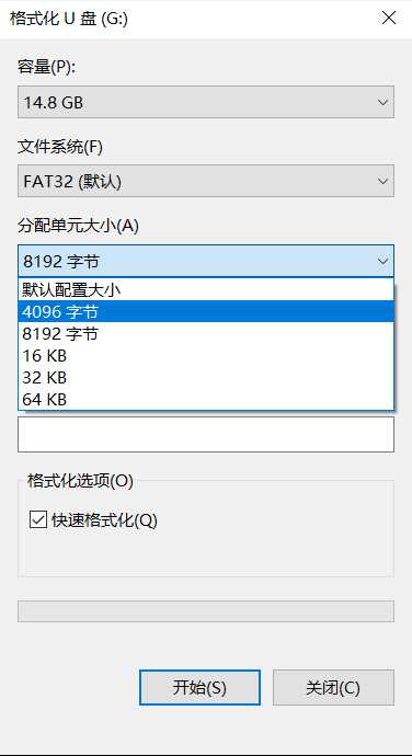
- 将SD卡插入电脑进行格式化
格式化时,要将SD卡格式化为FAT32文件系统。块大小格式化为4096字节时后面会出现无法启动的情况,可以先复现一下这个错误。块大小我选择4096字节。
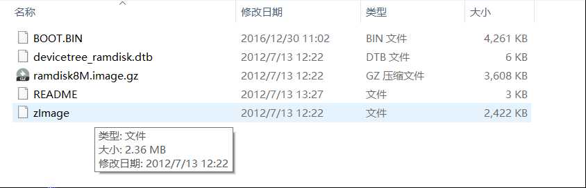
- 然后将ZedBoard_OOB_Design文件夹下sd_image文件夹内的文件拷贝进格式化后的SD卡里。
- zedboard开发板断电,插上SD卡,将电源线和USB转uart线接好,先不加电。然后打开设备管理器,查看分配好的串口号。
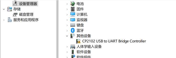
突然发现驱动还没安装,好吧,先安装驱动。找到CP2102的驱动,安装之。
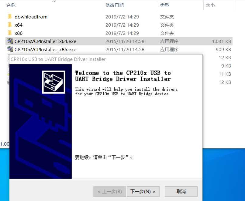
一路next就行了,然后更新设备管理器,发现出现了串口号。
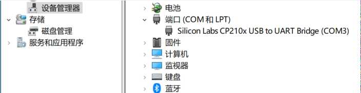
- 打开Putty软件,选择使用serial(串口)登录,配置好串口号和波特率就行了,串口号设置COM3,波特率为115200.
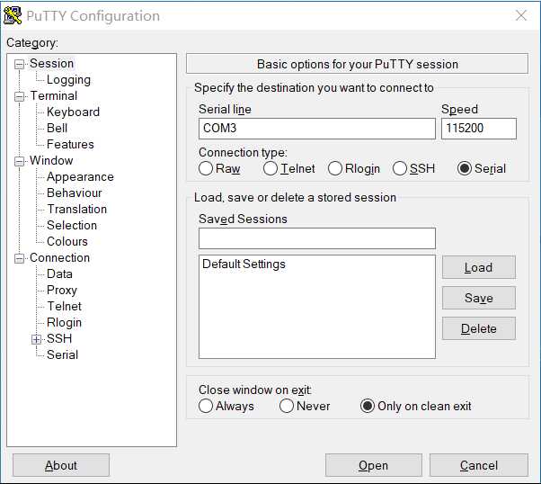
- 设置好后,点open,然后zedboard打开开关。
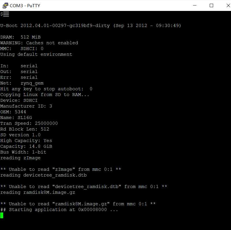
然后就会发现出现无法从分区中读取文件,进而导致启动失败的情况。按下PS-RST按钮复位一下,还是这种情况。
下面测试另一种情况,将SD卡格式化时,块大小设置为8192,重复上述步骤,可以看到能正常启动。
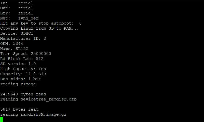
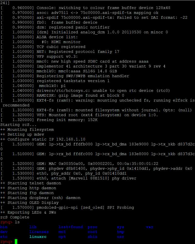
接下来就和终端操作Linux别无二致了,只不过这是通过串口进行的。
测试发现,格式化时,块大小设置上只要大于等于8192字节都可以启动成功,至于为什么4096字节的块大小无法启动,我也很纳闷。
测试
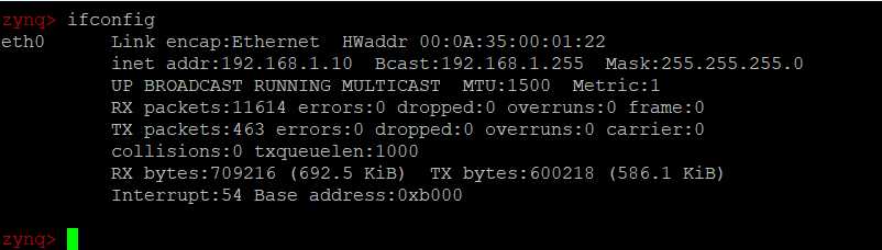
- 启动后,即可进行测试,首先测试以太网。用网线将zedboard和电脑直连,此时串口界面会提示以太网连接。

可以看出,这是一个千兆全速率的以太网连接,使用ifconfig工具查看网络信息,zedboard的IP为192.168.1.10
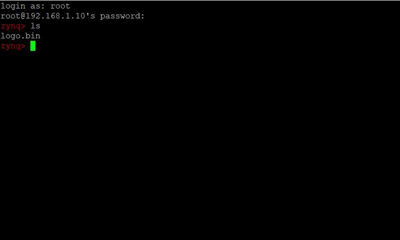
- 接下来测试以太网的SSH,使用putty软件的SSH连接zedboard。
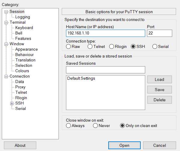
登录用户名为root,密码也为root。
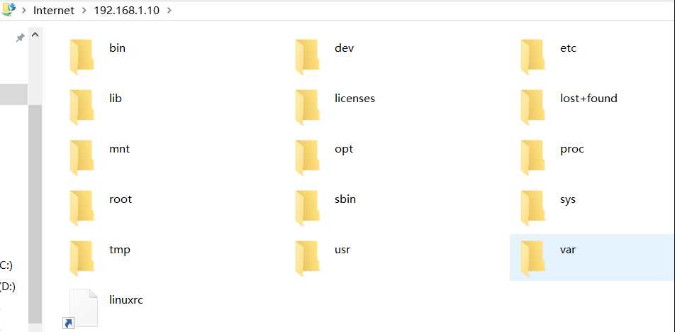
- 接下来测试FTP,打开文件管理器,输入FTP地址,即可看到zedboard板上Linux的文件目录,可以上传和下载文件。

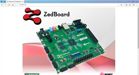
- 接下来测试HTTP,打开浏览器,输入http://192.168.1.10,即可打开zedboard内置的http服务器主页。
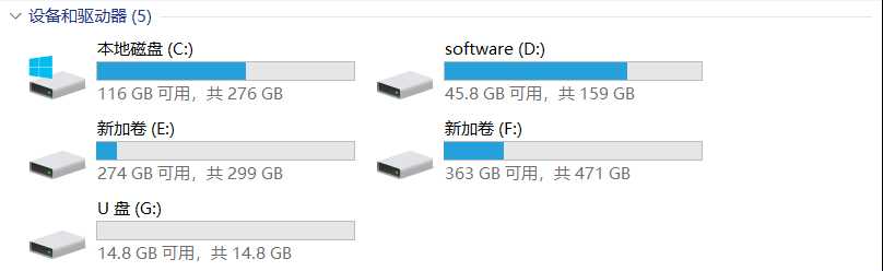
- 测试USB-OTG。将USB-OTG线插入zedboard上的USB-OTG的microUSB接口,然后OTG线上插入一个U盘,在Linux中查看U盘。
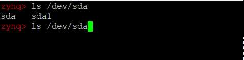
可以看到有一个sda1设备,进一步确定是否是U盘。
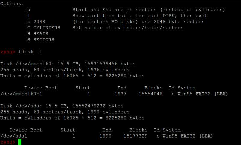
可以看到有两个16G的设备,其中mmcblk0是本机的SD卡,而sda1则是U盘,挂载之。
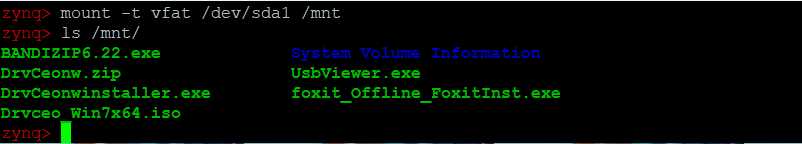
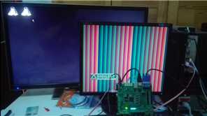
挂载后即可读写U盘中的文件。 - 测试VGA和HDMI,这个就不放图了,从网上找了一张图,VGA会显示两只小企鹅,HDMI会显示色带,DIGILENT的logo会在屏幕上弹弹弹弹弹。
- 测试在Linux中读取拨码开关的状态。
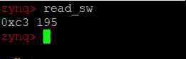
此时拨码开关的状态为0xc3,即二进制的1100_0011,十进制的195,与实际情况一致。 - 在Linux中设置LED灯的状态。
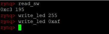
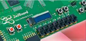
Write_led 255即设置8个LED全亮,十进制255对应二进制1111_1111,0xaf类似,只是用十六进制表示而已。 - 测试OLED,在zedboard上有一个OLED显示屏,就是下图中的显示屏,启动后OLED显示屏上显示的是DIGILENT的logo,此处就不放图了。
结语
其实所有的测试内容都在zedboard文档内,该文档在第一步往SD卡里复制文件时就可以发现,在文件夹sd_image里。
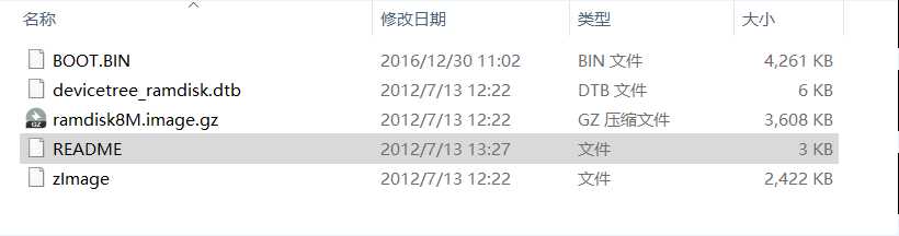
上图的README文档即是测试指导文档。
文档内容如下:
------------------------------------------------
*** ZED DEMONSTRATION IMAGE ***
------------------------------------------------
*this document is meant to be viewed as a monospaced font
The files on this SD card may be used to boot a simple Linux image with
functionality that demonstrates the basic capabilities of the ZED board.
To boot this image, first insert the SD card into the ZED board, and
ensure that the jumpers are set as follows:
MIO 6: set to GND
MIO 5: set to 3V3
MIO 4: set to 3V3
MIO 3: set to GND
MIO 2: set to GND
VADJ Select: Set to 1V8
JP6: shorted
JP2: shorted
All other jumpers should be left unshorted.
Attach a computer running a terminal emulator to the UART port with a
USB micro cable. Configure the terminal emulator as follows:
Baud : 115200
8 data bits
1 stop bit
no parity
Attach a 12 V power supply to the ZED board and power it on. Connect to
the appropriate COM port in the terminal emulator. The boot process
should finish in about a minute. You will know boot-up has completed
when pressing return at the terminal presents you with a red "zynq>"
prompt.
When you are done using Linux, you should run the command:
poweroff
and then switch off the ZED board.
------------
* FEATURES *
------------
USB-OTG: To use USB devices with the ZED board, first connect a hub
to the USB-OTG port. USB devices attached to this hub can then be
accessed in Linux. USB thumbdrives attached in this manner can be
mounted with read/write access.
ETHERNET: After boot-up a dropbear ssh server, fttpd FTP server, and
a httpd HTTP server will be running. Refer to the documentation on
these servers if you are interested in using them. A default website
is hosted on the httpd server that can be reached at the static IP:
192.168.1.10.
VGA: A test pattern is output on the VGA connector by the programmable
logic.
SWITCHES/LEDS: Scripts are included for writing to the LEDs and reading
the state of the switches. To read the state of the switches, run the
command:
read_sw
It will return the state of the switches as both hexadecimal and decimal.
A script for changing the state of the LEDs is also included. To turn all
8 LEDs on, run one of the following two commands:
write_led 255
write_led 0xFF
LD9 is used to indicate read/write activity on the SD card.
OLED DISPLAY: A default image is displayed on the OLED after Linux
has finished booting. In order to prolong the life of the OLED display,
the manufacturer suggests that a specific powerdown sequence be used.
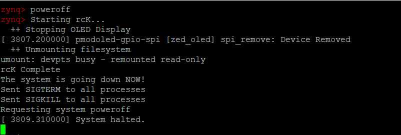
Running the poweroff command before switching the ZED board off will
ensure that this procedure is correctly followed.最后最后,记得关机下电之前使用poweroff指令关机。
然后愉快收工。
以上是关于1_ZedBoard开发板测试的主要内容,如果未能解决你的问题,请参考以下文章