Esp8266学习2. Node-mcu基于Arduino IDE2.0.3设置及基本操作
Posted 编程圈子
tags:
篇首语:本文由小常识网(cha138.com)小编为大家整理,主要介绍了Esp8266学习2. Node-mcu基于Arduino IDE2.0.3设置及基本操作相关的知识,希望对你有一定的参考价值。
Esp8266学习2. Node-mcu基于Arduino IDE2.0.3设置及基本操作
一、准备工作
1. 下载Aruino IDE
这里使用 2.0.3 版本。
https://www.arduino.cc/en/Main/Software
下载后安装。
2. 准备Node-MCU开发板
二、设置
1. 填写开发板网址
点击 File-Preferences,到Additional boards manager URLs,填写:
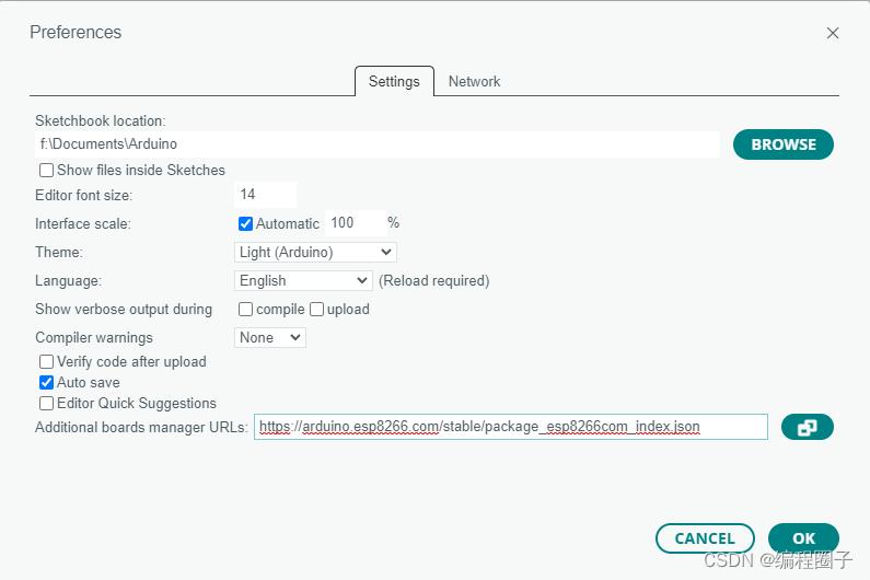
https://arduino.esp8266.com/stable/package_esp8266com_index.json
点击OK。
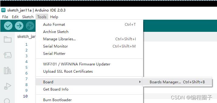
2. 开发板设置
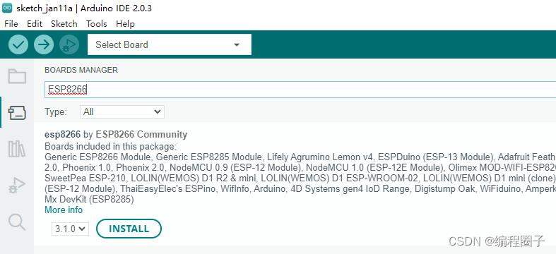
点击菜单 Tools-Board-Boards Manager
搜索ESP8266,点击Install。
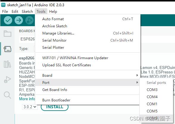
3. 连接开发板
把开发板连接到电脑,
点击Tools-Port-选择对应的开发板端口。
点击Select Board:
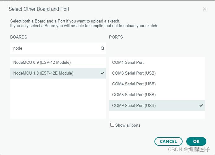
选择NodeMUC 1.0开发板。
提示下载库时点击YES。
三、测试点亮LED程序
1. 加载示例程序
点击File-Examples-01.Basics-Blink,加载程序如下:
/*
  Blink

  Turns an LED on for one second, then off for one second, repeatedly.

  Most Arduinos have an on-board LED you can control. On the UNO, MEGA and ZERO
  it is attached to digital pin 13, on MKR1000 on pin 6. LED_BUILTIN is set to
  the correct LED pin independent of which board is used.
  If you want to know what pin the on-board LED is connected to on your Arduino
  model, check the Technical Specs of your board at:
  https://www.arduino.cc/en/Main/Products

  modified 8 May 2014
  by Scott Fitzgerald
  modified 2 Sep 2016
  by Arturo Guadalupi
  modified 8 Sep 2016
  by Colby Newman

  This example code is in the public domain.

  https://www.arduino.cc/en/Tutorial/BuiltInExamples/Blink
*/

// the setup function runs once when you press reset or power the board
void setup()
  // initialize digital pin LED_BUILTIN as an output.
  pinMode(LED_BUILTIN, OUTPUT);


// the loop function runs over and over again forever
void loop()
  digitalWrite(LED_BUILTIN, HIGH);  // turn the LED on (HIGH is the voltage level)
  delay(1000);                      // wait for a second
  digitalWrite(LED_BUILTIN, LOW);   // turn the LED off by making the voltage LOW
  delay(1000);                      // wait for a second
2. 编译运行
点击如下菜单 :
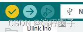
第一个按钮是编译,第二个按钮烧写。烧写完成控制台提示:
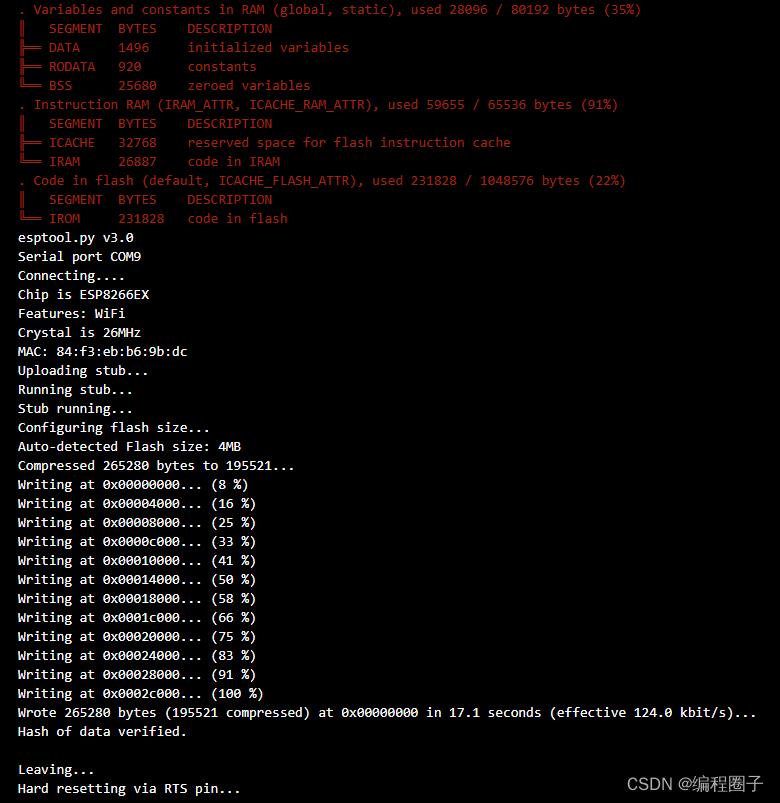
烧写后可以看到开发板的LED灯在闪烁。
四、一些基本网络操作
1. 连接到热点
引用库 <ESP8266Wifi.h>
代码:
#include <ESP8266WiFi.h>

#ifndef STASSID
#define STASSID "你的WIFI账号"
#define STAPSK "你的WIFI密码"
#endif

// SSID的账号与密码赋值
const char* ssid = STASSID;
const char* password = STAPSK;

// 必须指定WIFI工作模式
  WiFi.mode(WIFI_STA);
  WiFi.begin(ssid, password);

  while (WiFi.status() != WL_CONNECTED)
    delay(500);
    Serial.print(".");


  Serial.println("");
  Serial.println("WiFi connected");
  Serial.println("Get IP address: ");
  // 获取本地IP地址
  Serial.println(WiFi.localIP());
2. 使用WiFiClient
- WiFiClient client : 初始化类
- connect(host, port) : 创建连接
- client.readStringUntil(‘\\r’) : 读取一行
- client.read() : 从缓冲区读取数据
- client.connected() : 连接状态
- client.println(“”) :发送数据
- client.available() :缓冲区是否有数据
- client.stop() : 关闭连接
3. 创建http请求
使用WiFiClient类用来管理TCP连接。
 // 使用 WiFiClient 类创建TCP连接
  WiFiClient client;
  if (!client.connect(host, port))
    Serial.println("connection failed");
    delay(5000);
    return;


  // 发送数据给服务器
  Serial.println("sending data to server");
  if (client.connected())  client.println("hello from ESP8266");

  // 定义接收的超时时间
  unsigned long timeout = millis();
  while (client.available() == 0)
    if (millis() - timeout > 5000)
      Serial.println(">>> Client Timeout !");
      client.stop();
      delay(60000);
      return;


  // 把收到的数据打印出来
  Serial.println("receiving from remote server");
  // not testing 'client.connected()' since we do not need to send data here
  while (client.available())
    char ch = static_cast<char>(client.read());
    Serial.print(ch);


  // 关闭连接
  Serial.println();
  Serial.println("closing connection");
  client.stop();
以上是关于Esp8266学习2. Node-mcu基于Arduino IDE2.0.3设置及基本操作的主要内容,如果未能解决你的问题,请参考以下文章