如何捕获TTL的通讯-工业总线协议分析
Posted 亿企创新-莫学良
tags:
篇首语:本文由小常识网(cha138.com)小编为大家整理,主要介绍了如何捕获TTL的通讯-工业总线协议分析相关的知识,希望对你有一定的参考价值。
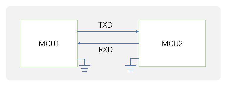
需求:
当你想要了解两个MCU之间的TTL通讯内容时,我们可以通过对TTL数据总线上的数据进行监听,本文讲述监听的原理和实现方法。
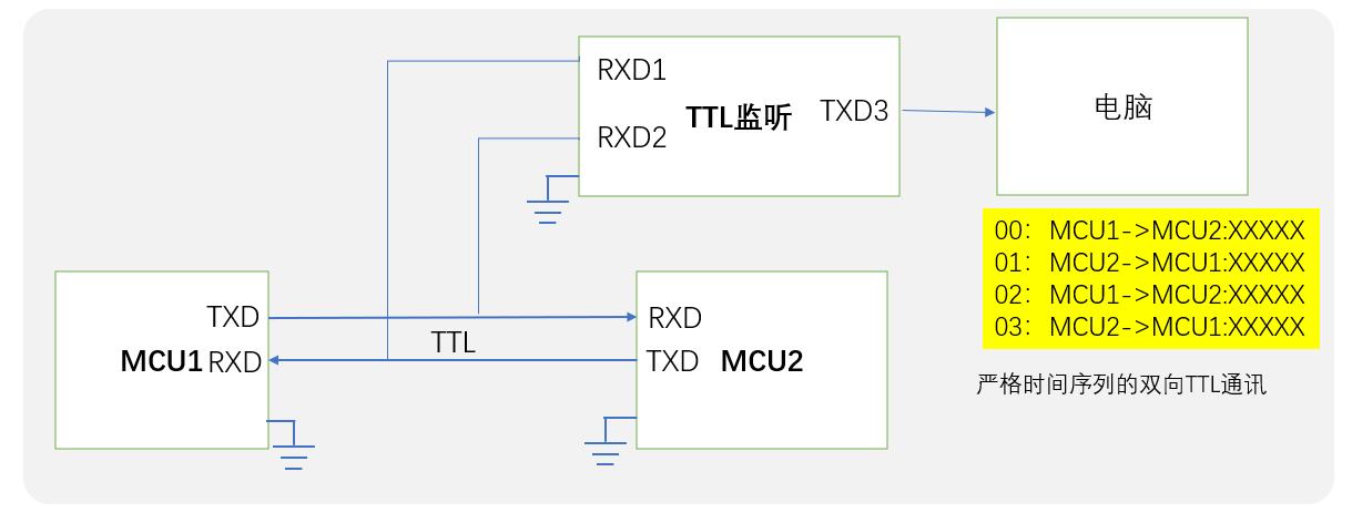
方法1:开发板编程监听
通过第三个MCU做TTL监听,如下图所示,这个MCU的两个串口,分别监听两根TTL数据线,然后通过第三个串口把数据发送出来。
常见的单片机是STM32F103,有三个串口,可以实现这个功能,后面给出详细的源码。
方案优点:
可以直接串口接收,生成通讯对话过程;
方案缺点:
1.需要编程实现;
2.需要知道通讯波特率,这点要么是猜测常见的波特率,如9600,115200,38400等,要么是用方法2的方法去探测。
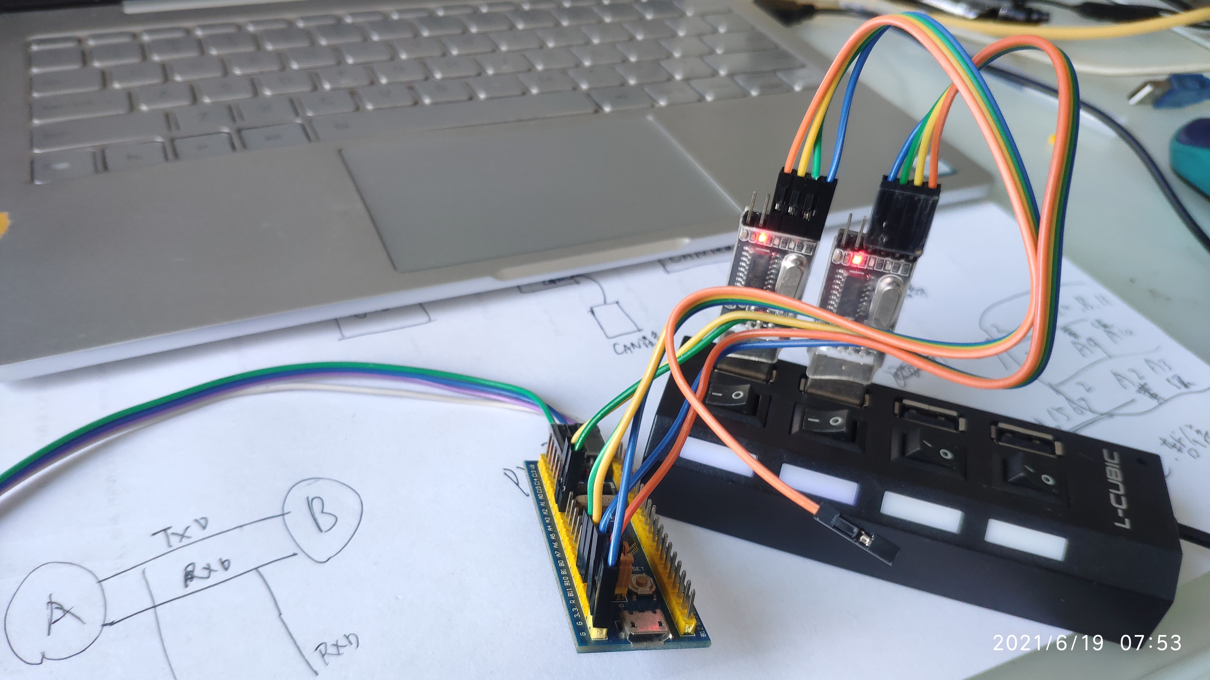
所幸实现该功能的STM32F103的程序我已经写好,下载到板子上,可以正常运行。
三个串口分别为:
UART1: PA9,PA10(RXD)
UART2:PA2,PA3(RXD)
UART3: PB10,PB11
因此将PA10和PA3作为监听线并在TTL总线上,就可以实现监听。
#include "stm32f10x.h"  //°üº¬ÐèÒªµÄÍ·Îļþ
#include "main.h"       //°üº¬ÐèÒªµÄÍ·Îļþ
#include "delay.h"      //°üº¬ÐèÒªµÄÍ·Îļþ
#include "usart1.h"     //°üº¬ÐèÒªµÄÍ·Îļþ


void My_USART1_Init(void)
{
	GPIO_InitTypeDef GPIO_InitStrue;
	USART_InitTypeDef USART_InitStrue;
	NVIC_InitTypeDef NVIC_InitStrue;

	RCC_APB2PeriphClockCmd(RCC_APB2Periph_GPIOA,ENABLE);    //GPIO????
	RCC_APB2PeriphClockCmd(RCC_APB2Periph_USART1,ENABLE);   //????

	GPIO_InitStrue.GPIO_Mode=GPIO_Mode_AF_PP;               //????
	GPIO_InitStrue.GPIO_Pin=GPIO_Pin_9;                     //PA9
	GPIO_InitStrue.GPIO_Speed=GPIO_Speed_10MHz;             //????
  GPIO_Init(GPIOA,&GPIO_InitStrue);                       //GPIO?????

	GPIO_InitStrue.GPIO_Mode=GPIO_Mode_IN_FLOATING;         //????
	GPIO_InitStrue.GPIO_Pin=GPIO_Pin_10;                    //PA10
	GPIO_InitStrue.GPIO_Speed=GPIO_Speed_10MHz;             //????
  GPIO_Init(GPIOA,&GPIO_InitStrue);                       //GPIO?????

	USART_InitStrue.USART_BaudRate = 115200  ;                                     //???
	USART_InitStrue.USART_HardwareFlowControl=USART_HardwareFlowControl_None;      //????
	USART_InitStrue.USART_Mode=USART_Mode_Tx|USART_Mode_Rx;                        //??????
	USART_InitStrue.USART_Parity=USART_Parity_No;                                  //???
	USART_InitStrue.USART_StopBits=USART_StopBits_1;                               //???
	USART_InitStrue.USART_WordLength=USART_WordLength_8b;                          //???
	USART_Init(USART1,&USART_InitStrue);                                           //???????

	USART_Cmd(USART1,ENABLE);                            //????1
	USART_ITConfig(USART1,USART_IT_RXNE,ENABLE);         //??????

	NVIC_InitStrue.NVIC_IRQChannel=USART1_IRQn;          //??IRQ??
	NVIC_InitStrue.NVIC_IRQChannelCmd=ENABLE;            //????
	NVIC_InitStrue.NVIC_IRQChannelPreemptionPriority=1;  //?????
	NVIC_InitStrue.NVIC_IRQChannelSubPriority=1;         //
	NVIC_Init(&NVIC_InitStrue);                          //?????


}


void My_USART2_Init(void)
{
	GPIO_InitTypeDef GPIO_InitStructure;
    NVIC_InitTypeDef NVIC_InitStructure;
    USART_InitTypeDef USART_InitStructure;

    /* Enable the USART2 Pins Software Remapping */
    RCC_APB2PeriphClockCmd(RCC_APB2Periph_GPIOA|RCC_APB2Periph_AFIO, ENABLE);
    RCC_APB1PeriphClockCmd(RCC_APB1Periph_USART2|RCC_APB2Periph_AFIO, ENABLE);

    /* Configure USART2 Rx (PA.03) as input floating */
    GPIO_InitStructure.GPIO_Pin = GPIO_Pin_3;
    GPIO_InitStructure.GPIO_Mode = GPIO_Mode_IPU;
    GPIO_Init(GPIOA, &GPIO_InitStructure);

    /* Configure USART2 Tx (PA.02) as alternate function push-pull */
    GPIO_InitStructure.GPIO_Pin = GPIO_Pin_2;
    GPIO_InitStructure.GPIO_Speed = GPIO_Speed_50MHz;
    GPIO_InitStructure.GPIO_Mode = GPIO_Mode_AF_PP;
    GPIO_Init(GPIOA, &GPIO_InitStructure);

    /* Enable the USART2 Interrupt */
    NVIC_InitStructure.NVIC_IRQChannel = USART2_IRQn;
    NVIC_InitStructure.NVIC_IRQChannelPreemptionPriority = 2;
    NVIC_InitStructure.NVIC_IRQChannelSubPriority = 2;
    NVIC_InitStructure.NVIC_IRQChannelCmd = ENABLE;
    NVIC_Init(&NVIC_InitStructure);

    USART_InitStructure.USART_BaudRate = 115200;
    USART_InitStructure.USART_WordLength = USART_WordLength_8b;
    USART_InitStructure.USART_StopBits = USART_StopBits_1;
    USART_InitStructure.USART_Parity = USART_Parity_No;
    USART_InitStructure.USART_HardwareFlowControl = USART_HardwareFlowControl_None;
    USART_InitStructure.USART_Mode = USART_Mode_Rx | USART_Mode_Tx;

    USART_Init(USART2, &USART_InitStructure);
    USART_ITConfig(USART2, USART_IT_RXNE, ENABLE);
    /* Enable USART2 */
    USART_Cmd(USART2, ENABLE);
}


void My_USART3_Init(void)
{
	  GPIO_InitTypeDef GPIO_InitStructure;
    NVIC_InitTypeDef NVIC_InitStructure;
    USART_InitTypeDef USART_InitStructure;

    /* Enable the USART3 Pins Software Remapping */
    RCC_APB2PeriphClockCmd(RCC_APB2Periph_GPIOB, ENABLE);
    RCC_APB1PeriphClockCmd(RCC_APB1Periph_USART3, ENABLE);

    /* Configure USART3 Rx (PB.11) as input floating */
    GPIO_InitStructure.GPIO_Pin = GPIO_Pin_11;
    GPIO_InitStructure.GPIO_Mode = GPIO_Mode_IPU;
    GPIO_Init(GPIOB, &GPIO_InitStructure);

    /* Configure USART3 Tx (PB.10) as alternate function push-pull */
    GPIO_InitStructure.GPIO_Pin = GPIO_Pin_10;
    GPIO_InitStructure.GPIO_Speed = GPIO_Speed_50MHz;
    GPIO_InitStructure.GPIO_Mode = GPIO_Mode_AF_PP;
    GPIO_Init(GPIOB, &GPIO_InitStructure);

    /* Enable the USART3 Interrupt */
    NVIC_InitStructure.NVIC_IRQChannel = USART3_IRQn;
    NVIC_InitStructure.NVIC_IRQChannelPreemptionPriority = 3;
    NVIC_InitStructure.NVIC_IRQChannelSubPriority = 3;
    NVIC_InitStructure.NVIC_IRQChannelCmd = ENABLE;
    NVIC_Init(&NVIC_InitStructure);

    USART_InitStructure.USART_BaudRate = 115200;
    USART_InitStructure.USART_WordLength = USART_WordLength_8b;
    USART_InitStructure.USART_StopBits = USART_StopBits_1;
    USART_InitStructure.USART_Parity = USART_Parity_No;
    USART_InitStructure.USART_HardwareFlowControl = USART_HardwareFlowControl_None;
    USART_InitStructure.USART_Mode = USART_Mode_Rx | USART_Mode_Tx;

    USART_Init(USART3, &USART_InitStructure);
    USART_ITConfig(USART3, USART_IT_RXNE, ENABLE);
    /* Enable USART3 */
    USART_Cmd(USART3, ENABLE);
}


void USART1_IRQHandler(void)
{
	u8 res;
	 if(USART_GetITStatus(USART1,USART_IT_RXNE))
 {
     res= USART_ReceiveData(USART1);
     USART_SendData(USART3,res);
  }
}

void USART2_IRQHandler(void)
{
	u8 res;
	 if(USART_GetITStatus(USART2,USART_IT_RXNE))
 {
     res= USART_ReceiveData(USART2);
     USART_SendData(USART3,res);
  }
}


void USART3_IRQHandler(void)
{
	u8 res;
	 if(USART_GetITStatus(USART3,USART_IT_RXNE))
 {
     res= USART_ReceiveData(USART3);
     //USART_SendData(USART3,res);
  }
}

 int main(void)
 {
	 NVIC_PriorityGroupConfig(NVIC_PriorityGroup_2);

	My_USART1_Init();
	My_USART2_Init();
	My_USART3_Init();


	while(1)
	{

		Delay_Ms(300);
	}
 }
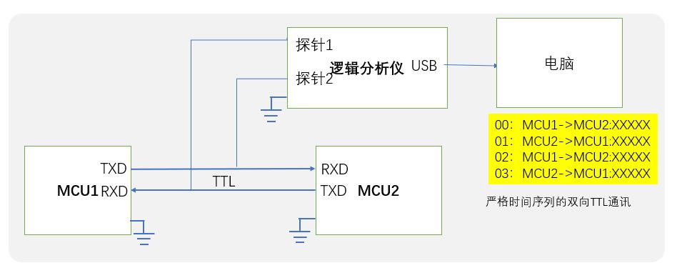
方法2:逻辑分析仪监听
使用逻辑分析仪,将探针接到TTL总线上,开始捕获。
以上是关于如何捕获TTL的通讯-工业总线协议分析的主要内容,如果未能解决你的问题,请参考以下文章