Arduino处理STM32中的多个串口通讯问题
Posted 卓晴
tags:
篇首语:本文由小常识网(cha138.com)小编为大家整理,主要介绍了Arduino处理STM32中的多个串口通讯问题相关的知识,希望对你有一定的参考价值。

简 介: 对于在Arduino下开发STM32的程序,对于STM32所具有的三个硬件USART进行测测试。结果显示可以使用这些串口完成相应的数据的输入与输出。但是涉及到以下两个问题,还没有得到解决:问题一:如何将USART1的管脚重新映射到PB6,PB7? 问题二:如何使用SoftwareSerial?
关键词: Arduino,STM32,USART
§01 STM32F103C 的串口
1、基于Arduino生成STM32程序
在 从0开始构建Arduino 介绍了从单颗芯片构建完整的STM32F103C的开发系统。利用了原本STM23BOOTLOADER(基于串口USART1下载器)完成对芯片的更新。Arduino IDE编程生成运行程序的BIN文件,下载到目标MCU中,便可以运行了。
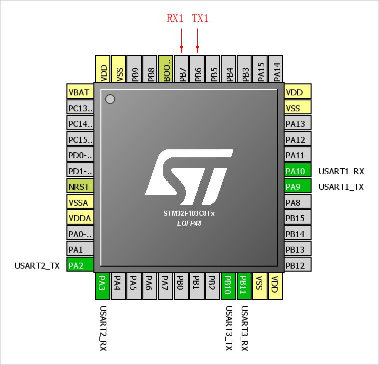
在STM32F103C中存在大量的外设。三个USART是它最为精彩的地方,利用USART可以与很多的其它模块相连。下图是从STM32CubeMX给出的STM32F103C的三个串口的管脚图。对于UART1它有两个可以配置的不同的管脚。

▲ 图1-1 STM32F103C8Tx 的串口分布
下面通过实验来验证如下问题:
- 如何在Arduino 中合理的 使用这些USART呢?
- 如何设置软件串口?
2、应用多个硬件串口
在 STM32duino III. - How to use Serial (USART) 介绍了使用STM32多个串口的Arduino的基本程序。但是测试之后,其中使用HardwareSerial 声明串口的形式会出现编译错误。
在从0开始构建Arduino测试了Arduino缺省情况下串口的使用。它利用了USART1(分布在PA9,PA10)的使用情况。
在STM32中,分别使用Serial1, Serial2, Serial3来访问者三个硬件串口。
(1)测试程序
/*
**==============================================================================
** TEST1.C:             -- by Dr. ZhuoQing, 2021-05-31
**
**==============================================================================
*/
#include <HardwareSerial.h>
#define ON(pin)                 digitalWrite(pin, HIGH)
#define OFF(pin)                digitalWrite(pin, LOW)
#define VAL(pin)                digitalRead(pin)
#define IN(pin)                 pinMode(pin, INPUT)
#define OUT(pin)                pinMode(pin, OUTPUT)
#define LED PB12
#define LED1 PB2
//------------------------------------------------------------------------------
void setup(void) {
    pinMode(LED, OUTPUT);
    OUT(LED1);
    Serial.begin(115200);
    Serial.setTimeout(1);
    Serial.println("Test Hello...");
    Serial2.begin(115200);
    Serial3.begin(9600);
}
//------------------------------------------------------------------------------
int nCount = 0;
void loop(void) {
    int nNumber;
    if(Serial.available() > 0) {
        nNumber = Serial.parseInt();
        Serial.println(nNumber);
    }
    delay(100);
    nCount ++;
    if(nCount & 0x1) {
        ON(LED);
    } else OFF(LED);
    Serial2.write('U');
    Serial3.write('V');
}
//==============================================================================
//                END OF FILE : TEST1.C
//------------------------------------------------------------------------------
(2)测试结果
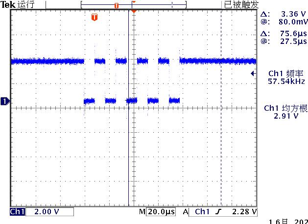
可以从UART1接收到“Test Hello”字符串。在PA2,PB10测量到波特率分别为115200, 9600的通信波形脉冲。
下图是测量PA2发送的115200波特率的’U’字符的波形。

▲ 图1-2 测量PA2发送的115200波特率的'U'字符的波形
3、如何修改Serial的端口
Serial1对应的USART1,它有两个可能的端口,缺省是 PA9、PA10,还可以通过软件修改到PB6、PB7。
在 STM32的Arduino的引脚映射 给出了Arduino中PWM,IO,ADC,UART的配置。似乎说明在STM32中的UART1只能使用PA9,PA10。
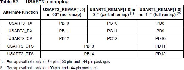
(1)USART端口重新映射
在STM32用户手册中给出了利用 AFIO_MAPR寄存器对于外设端口进行重新映射的配置。在48-pin中,实际上只有USART1能够重新6映射。

▲ 图1-3 USART3端口重新映射

▲ 图1-4 USART2端口重新映射

▲ 图1-5 USART1端口重新映射
(2)AFIO_MAPR寄存器
-
AFIO_MAPR:
-
地址:0x4:
缺省值:0x0:

▲ 图1-6 AFI_MAPR 寄存器的配置
根据前面USART1重新映射来看,需要将AFIO_MAPR的bit2置1.。
AFIO_MAPR |= 0x4
在Arduino中支持一下 AFIO的命令。但是修改完之后,并没有倍率PB7,PB6上测量到输出信号。
afio_remap(AFIO_REMAP_USART1);
所以到现在为止还没有找到对于STM32F103在Arduino下重新将USART1映射到PB6,PB7的方法。
§02 软件UART
测试STM32F103是否在Arduinoxw支持软件UART1。
直接在Arduino中使用SoftwareSerial 会出现不支持的错误。这个问题需要进一步从: STM32F103, USART, SoftwareSerial Library 进行查询。
※ 博文附件 ※
在下面给出了STM32 Serial.H的内容: Arduino_STM32
/******************************************************************************
 * The MIT License
 *
 * Copyright (c) 2010 Perry Hung.
 * Copyright (c) 2011, 2012 LeafLabs, LLC.
 *
 * Permission is hereby granted, free of charge, to any person
 * obtaining a copy of this software and associated documentation
 * files (the "Software"), to deal in the Software without
 * restriction, including without limitation the rights to use, copy,
 * modify, merge, publish, distribute, sublicense, and/or sell copies
 * of the Software, and to permit persons to whom the Software is
 * furnished to do so, subject to the following conditions:
 *
 * The above copyright notice and this permission notice shall be
 * included in all copies or substantial portions of the Software.
 *
 * THE SOFTWARE IS PROVIDED "AS IS", WITHOUT WARRANTY OF ANY KIND,
 * EXPRESS OR IMPLIED, INCLUDING BUT NOT LIMITED TO THE WARRANTIES OF
 * MERCHANTABILITY, FITNESS FOR A PARTICULAR PURPOSE AND
 * NONINFRINGEMENT. IN NO EVENT SHALL THE AUTHORS OR COPYRIGHT HOLDERS
 * BE LIABLE FOR ANY CLAIM, DAMAGES OR OTHER LIABILITY, WHETHER IN AN
 * ACTION OF CONTRACT, TORT OR OTHERWISE, ARISING FROM, OUT OF OR IN
 * CONNECTION WITH THE SOFTWARE OR THE USE OR OTHER DEALINGS IN THE
 * SOFTWARE.
 *****************************************************************************/

/**
 * @file wirish/include/wirish/HardwareSerial.h
 * @brief Wirish serial port interface.
 */

#ifndef _WIRISH_HARDWARESERIAL_H_
#define _WIRISH_HARDWARESERIAL_H_

#include <libmaple/libmaple_types.h>

#include "Print.h"
#include "boards.h"
#include "Stream.h"
/*
 * IMPORTANT:
 *
 * This class documented "by hand" (i.e., not using Doxygen) in the
 * leaflabs-docs/ repository.
 *
 * If you alter the public HardwareSerial interface, you MUST update
 * the documentation accordingly.
 */

// Define constants and variables for buffering incoming serial data.  We're
// using a ring buffer (I think), in which head is the index of the location
// to which to write the next incoming character and tail is the index of the
// location from which to read.
#if !(defined(SERIAL_TX_BUFFER_SIZE) && defined(SERIAL_RX_BUFFER_SIZE))
#if (RAMEND < 1000)
#define SERIAL_TX_BUFFER_SIZE 16
#define SERIAL_RX_BUFFER_SIZE 16
#else
#define SERIAL_TX_BUFFER_SIZE 64
#define SERIAL_RX_BUFFER_SIZE 64
#endif
#endif
#if (SERIAL_TX_BUFFER_SIZE>256)
typedef uint16_t tx_buffer_index_t;
#else
typedef uint8_t tx_buffer_index_t;
#endif
#if  (SERIAL_RX_BUFFER_SIZE>256)
typedef uint16_t rx_buffer_index_t;
#else
typedef uint8_t rx_buffer_index_t;
#endif

struct usart_dev;

/* Roger Clark
 *
 * Added config defines from AVR
 * Note. The values will need to be changed to match STM32 USART config register values, these are just place holders.
 */
// Define config for Serial.begin(baud, config);
// Note. STM32 doesn't support as many different Serial modes as AVR or SAM cores.
// The word legth bit M must be set when using parity bit.

#define SERIAL_8N1	0B00000000
#define SERIAL_8N2	0B00100000
#define SERIAL_9N1	0B00001000
#define SERIAL_9N2	0B00101000

#define SERIAL_8E1	0B00001010
#define SERIAL_8E2	0B00101010
/* not supported:
#define SERIAL_9E1	0B00001010
#define SERIAL_9E2	0B00101010
*/
#define SERIAL_8O1	0B00001011
#define SERIAL_8O2	0B00101011
/* not supported:
#define SERIAL_9O1	0B00001011
#define SERIAL_9O2	0B00101011
*/

/* Roger Clark
 * Moved macros from hardwareSerial.cpp
 */

#define DEFINE_HWSERIAL(name, n)                                   \\
	HardwareSerial name(USART##n,                                  \\
						BOARD_USART##n##_TX_PIN,                   \\
						BOARD_USART##n##_RX_PIN)

#define DEFINE_HWSERIAL_UART(name, n)                             \\
	HardwareSerial name(UART##n,                                  \\
						BOARD_USART##n##_TX_PIN,                   \\
						BOARD_USART##n##_RX_PIN)

/* Roger clark. Changed class inheritance from Print to Stream.
 * Also added new functions for peek() and availableForWrite()
 * Note. AvailableForWrite is only a stub function in the cpp
 */
class HardwareSerial : public Stream {

public:
    HardwareSerial(struct usart_dev *usart_device,
                   uint8 tx_pin,
                   uint8 rx_pin);

    /* Set up/tear down */
    void begin(uint32 baud);
    void begin(uint32 baud,uint8_t config);
    void end();
    virtual int available(void);
    virtual int peek(void);
    virtual int read(void);
    int availableForWrite(void);
    virtual void flush(void);
    virtual size_t write(uint8_t);
    inline size_t write(unsigned long n) { return write((uint8_t)n); }
    inline size_t write(long n) { return write((uint8_t)n); }
    inline size_t write(unsigned int n) { return write((uint8_t)n); }
    inline size_t write(int n) { return write((uint8_t)n); }
    using Print::write;

    /* Pin accessors */
    int txPin(void) { return this->tx_pin; }
    int rxPin(void) { return this->rx_pin; }

	operator bool() { return true; }

    /* Escape hatch into libmaple */
    /* FIXME [0.0.13] documentation */
    struct usart_dev* c_dev(void) { return this->usart_device; }
private:
    struct usart_dev *usart_device;
    uint8 tx_pin;
    uint8 rx_pin;
  protected:
#if 0
    volatile uint8_t * const _ubrrh;
    volatile uint8_t * const _ubrrl;
    volatile uint8_t * const _ucsra;
    volatile uint8_t * const _ucsrb;
    volatile uint8_t * const _ucsrc;
    volatile uint8_t * const _udr;
    // Has any byte been written to the UART since begin()
    bool _written;

    volatile rx_buffer_index_t _rx_buffer_head;
    volatile rx_buffer_index_t _rx_buffer_tail;
    volatile tx_buffer_index_t _tx_buffer_head;
    volatile tx_buffer_index_t _tx_buffer_tail;
    // Don't put any members after these buffers, since only the first
    // 32 bytes of this struct can be accessed quickly using the ldd
    // instruction.
    unsigned char _rx_buffer[SERIAL_RX_BUFFER_SIZE];
    unsigned char _tx_buffer[SERIAL_TX_BUFFER_SIZE];
#endif
};

#ifndef SERIAL_USB
#define Serial	Serial1
#endif

#if BOARD_HAVE_USART1
extern HardwareSerial Serial1;
#endif
#if BOARD_HAVE_USART2
extern HardwareSerial Serial2;
#endif
#if BOARD_HAVE_USART3
extern HardwareSerial Serial3;
#endif
#if BOARD_HAVE_UART4
extern HardwareSerial Serial4;
#endif
#if BOARD_HAVE_UART5
extern HardwareSerial Serial5;
#endif
#if BOARD_HAVE_USART6
extern HardwareSerial Serial6;
#endif

#endif	//_WIRISH_HARDWARESERIAL_H_
以上是关于Arduino处理STM32中的多个串口通讯问题的主要内容,如果未能解决你的问题,请参考以下文章