## 利用MPU6050 + OLED屏显示cube3D矩形效果
Posted perseverance52
tags:
篇首语:本文由小常识网(cha138.com)小编为大家整理,主要介绍了## 利用MPU6050 + OLED屏显示cube3D矩形效果相关的知识,希望对你有一定的参考价值。
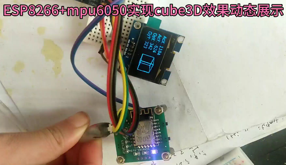
利用MPU6050 + OLED屏显示cube3D矩形效果
本次实验移植到ESP8266板子上
- 更换了所使用到的库
- 采用的是1.3寸的屏幕显示,也可以切换为0.96寸屏幕显示,只需更改一下接口定义就可以了,程序代码已预留出来了 。
视频效果:
||ESP8266+MPU6050实现动态调整cube
MPU6050配合OLED
用到的硬件:
- ESP8266 x 1
- MPU6050 (Accelerometer + Gyro Sensor) Module x 1
- 0.96″或者1.3" I2C OLED Display x 1
arduino 程序代码:
#include "SH1106Wire.h" //1.3寸用这个
//#include "SSD1306Wire.h"    //0.96寸用这个
#include "OLEDDisplayUi.h"
#include <Wire.h>
#if defined(ESP8266)    //OLED引脚定义
const int SDA_PIN = D2; //对应nodemcu接D5或者D1,,wemosD1mini的D2
const int SDC_PIN = D1; //对应nodemcu接D6或者D2,,wemosD1mini的D5
#else
const int SDA_PIN = D1; //对应nodemcu接D5或者D1
const int SCL = D2;     //对应nodemcu接D6或者D2
#endif

const int I2C_DISPLAY_ADDRESS = 0x3c;                      //I2c地址默认

SH1106Wire display(I2C_DISPLAY_ADDRESS, SDA_PIN, SDC_PIN); // 1.3寸用这个
//SSD1306Wire     display(I2C_DISPLAY_ADDRESS, SDA_PIN, SDC_PIN);   // 0.96寸用这个

 OLEDDisplayUi ui     ( &display );

//MPU
const int MPU=0x68;  // I2C address of the MPU-6050
int16_t AcX,AcY,AcZ,Tmp,GyX,GyY,GyZ;

float xx,xy,xz;
float yx,yy,yz;
float zx,zy,zz;

float fact;

int Xan,Yan;

int Xoff;
int Yoff;
int Zoff;

struct Point3d
{
  int x;
  int y;
  int z;
};

struct Point2d
{
  int x;
  int y;
};


int LinestoRender; // lines to render.
int OldLinestoRender; // lines to render just in case it changes. this makes sure the old lines all get erased.

struct Line3d
{
  Point3d p0;
  Point3d p1;
};

struct Line2d
{
  Point2d p0;
  Point2d p1;
};

Line3d Lines[12];  //Number of lines to render
Line2d Render[12];
Line2d ORender[12];

// Sets the global vars for the 3d transform. Any points sent through "process" will be transformed using these figures.
// only needs to be called if Xan or Yan are changed.
void SetVars(void)
{
  float Xan2,Yan2,Zan2;
  float s1,s2,s3,c1,c2,c3;

  Xan2 = Xan / fact; // convert degrees to radians.
  Yan2 = Yan / fact;

  // Zan is assumed to be zero

  s1 = sin(Yan2);
  s2 = sin(Xan2);

  c1 = cos(Yan2);
  c2 = cos(Xan2);

  xx = c1;
  xy = 0;
  xz = -s1;

  yx = (s1 * s2);
  yy = c2;
  yz = (c1 * s2);

  zx = (s1 * c2);
  zy = -s2;
  zz = (c1 * c2);
}

// processes x1,y1,z1 and returns rx1,ry1 transformed by the variables set in SetVars()
// fairly heavy on floating point here.
// uses a bunch of global vars. Could be rewritten with a struct but not worth the effort.
void ProcessLine(struct Line2d *ret,struct Line3d vec)
{
  float zvt1;
  int xv1,yv1,zv1;

  float zvt2;
  int xv2,yv2,zv2;

  int rx1,ry1;
  int rx2,ry2;

  int x1;
  int y1;
  int z1;

  int x2;
  int y2;
  int z2;

  int Ok;

  x1=vec.p0.x;
  y1=vec.p0.y;
  z1=vec.p0.z;

  x2=vec.p1.x;
  y2=vec.p1.y;
  z2=vec.p1.z;

  Ok=0; // defaults to not OK

  xv1 = (x1 * xx) + (y1 * xy) + (z1 * xz);
  yv1 = (x1 * yx) + (y1 * yy) + (z1 * yz);
  zv1 = (x1 * zx) + (y1 * zy) + (z1 * zz);

  zvt1 = zv1 - Zoff;


  if( zvt1 < -5){
    rx1 = 256 * (xv1 / zvt1) + Xoff;
    ry1 = 256 * (yv1 / zvt1) + Yoff;
    Ok=1; // ok we are alright for point 1.
  }


  xv2 = (x2 * xx) + (y2 * xy) + (z2 * xz);
  yv2 = (x2 * yx) + (y2 * yy) + (z2 * yz);
  zv2 = (x2 * zx) + (y2 * zy) + (z2 * zz);

  zvt2 = zv2 - Zoff;


  if( zvt2 < -5){
    rx2 = 256 * (xv2 / zvt2) + Xoff;
    ry2 = 256 * (yv2 / zvt2) + Yoff;
  } else
  {
    Ok=0;
  }

  if(Ok==1){
  ret->p0.x=rx1;
  ret->p0.y=ry1;

  ret->p1.x=rx2;
  ret->p1.y=ry2;
  }
 // The ifs here are checks for out of bounds. needs a bit more code here to "safe" lines that will be way out of whack, so they dont get drawn and cause screen garbage.

}

void setup()   {
   Wire.begin();
   fact = 180 / 3.14159265358979323846264338327950; // conversion from degrees to radians.

  Xoff = 90; // positions the center of the 3d conversion space into the center of the OLED screen. This is usally screen_x_size / 2.
  Yoff = 32; // screen_y_size /2
  Zoff = 750;   //Size of cube, larger no. = smaller cube

// line segments to draw a cube. basically p0 to p1. p1 to p2. p2 to p3 so on.

// Front Face.

  Lines[0].p0.x=-50;
  Lines[0].p0.y=-50;
  Lines[0].p0.z=50;
  Lines[0].p1.x=50;
  Lines[0].p1.y=-50;
  Lines[0].p1.z=50;

  Lines[1].p0.x=50;
  Lines[1].p0.y=-50;
  Lines[1].p0.z=50;
  Lines[1].p1.x=50;
  Lines[1].p1.y=50;
  Lines[1].p1.z=50;

  Lines[2].p0.x=50;
  Lines[2].p0.y=50;
  Lines[2].p0.z=50;
  Lines[2].p1.x=-50;
  Lines[2].p1.y=50;
  Lines[2].p1.z=50;

  Lines[3].p0.x=-50;
  Lines[3].p0.y=50;
  Lines[3].p0.z=50;
  Lines[3].p1.x=-50;
  Lines[3].p1.y=-50;
  Lines[3].p1.z=50;


//back face.

  Lines[4].p0.x=-50;
  Lines[4].p0.y=-50;
  Lines[4].p0.z=-50;
  Lines[4].p1.x=50;
  Lines[4].p1.y=-50;
  Lines[4].p1.z=-50;

  Lines[5].p0.x=50;
  Lines[5].p0.y=-50;
  Lines[5].p0.z=-50;
  Lines[5].p1.x=50;
  Lines[5].p1.y=50;
  Lines[5].p1.z=-50;

  Lines[6].p0.x=50;
  Lines[6].p0.y=50;
  Lines[6].p0.z=-50;
  Lines[6].p1.x=-50;
  Lines[6].p1.y=50;
  Lines[6].p1.z=-50;

  Lines[7].p0.x=-50;
  Lines[7].p0.y=50;
  Lines[7].p0.z=-50;
  Lines[7].p1.x=-50;
  Lines[7].p1.y=-50;
  Lines[7].p1.z=-50;

// now the 4 edge lines.

  Lines[8].p0.x=-50;
  Lines[8].p0.y=-50;
  Lines[8].p0.z=50;
  Lines[8].p1.x=-50;
  Lines[8].p1.y=-50;
  Lines[8].p1.z=-50;

  Lines[9].p0.x=50;
  Lines[9].p0.y=-50;
  Lines[9].p0.z=50;
  Lines[9].p1.x=50;
  Lines[9].p1.y=-50;
  Lines[9].p1.z=-50;

  Lines[10].p0.x=-50;
  Lines[10].p0.y=50;
  Lines[10].p0.z=50;
  Lines[10].p1.x=-50;
  Lines[10].p1.y=50;
  Lines[10].p1.z=-50;

  Lines[11].p0.x=50;
  Lines[11].p0.y=50;
  Lines[11].p0.z=50;
  Lines[11].p1.x=50;
  Lines[11].p1.y=50;
  Lines[11].p1.z=-50;

  LinestoRender=12;
  OldLinestoRender=LinestoRender;

  // Initialize MPU
  Wire.beginTransmission(MPU);
  Wire.write(0x6B);  // PWR_MGMT_1 register
  Wire.write(0);     // set to zero (wakes up the MPU-6050)
  Wire.endTransmission(true);

  Serial.begin(9600);
  display.init();
  display.clear();
  display.display();
  //    display.flipScreenVertically(); //屏幕翻转
  // display.mirrorScreen();//使用分光棱镜显示需要用到此函数
  display.setContrast(100,5,0); //屏幕亮度
  delay(1000);
 ui.setTargetFPS(80);                   //刷新频率
  ui.disableAllIndicators();             //不显示页码小点。
 ui.enableAutoTransition();
  ui.setFrameAnimation(SLIDE_LEFT);           //切屏方向
  ui.setAutoTransitionForwards();//设置自动过渡方向,
 // ui.setFrames(frames, numberOfFrames);       // 设置框架和显示屏幕内容数
  //ui.setTimePerFrame(5000);                   //设置切换时间
  ui.setTimePerTransition(500);//设置转场大约所需要时间
  // ui.setOverlays(overlays, numberOfOverlays); //设置覆盖的画面数
  ui.init();// UI负责初始化显示

}


/***********************************************************************************************************************************/
void RenderImage( void)
{
  // renders all the lines after erasing the old ones.
  // in here is the only code actually interfacing with the OLED. so if you use a different lib, this is where to change it.

 for (int i=0; i<OldLinestoRender; i++ )
  {
   display.drawLine(ORender[i].p0.x,ORender[i].p0.y,ORender[i].p1.x,ORender[i].p1.y); // erase the old lines.
     display.display();
  }


  for (int i=0; i<LinestoRender; i++ )
  {
   display.drawLine(Render[i].p0.x,Render[i].p0.y,Render[i].p1.x,Render[i].p1.y);
     display.display();
  }
  OldLinestoRender=LinestoRender;


  Wire.beginTransmission(MPU);
  Wire.write(0x3B);  // starting with register 0x3B (ACCEL_XOUT_H)
  Wire.endTransmission(true);
  Wire.requestFrom(MPU,14,true);  // request a total of 14 registers
  AcX=Wire.read()<<8|Wire.read();  // 0x3B (ACCEL_XOUT_H) & 0x3C (ACCEL_XOUT_L)
  AcY=Wire.read()<<8|Wire.read();  // 0x3D (ACCEL_YOUT_H) & 0x3E (ACCEL_YOUT_L)
  AcZ=Wire.read()<<8|Wire.read();  // 0x3F (ACCEL_ZOUT_H) & 0x40 (ACCEL_ZOUT_L)
  Tmp=Wire.read()<<8|Wire.read();  // 0x41 (TEMP_OUT_H) & 0x42 (TEMP_OUT_L)
  GyX=Wire.read()<<8|Wire.read();  // 0x43 (GYRO_XOUT_H) & 0x44 (GYRO_XOUT_L)
  GyY=Wire.read()<<8|Wire.read();  // 0x45 (GYRO_YOUT_H) & 0x46 (GYRO_YOUT_L)
  GyZ=Wire.read()<<8|Wire.read();  // 0x47 (GYRO_ZOUT_H) & 0x48 (GYRO_ZOUT_L)
  // text display tests
  display.clear();
  display.setFont(ArialMT_Plain_12)以上是关于## 利用MPU6050 + OLED屏显示cube3D矩形效果的主要内容,如果未能解决你的问题,请参考以下文章