信号处理基于 FIR与IIR滤波器低通高通带通设计matlab源码含GUI
Posted Matlab咨询QQ1575304183
tags:
篇首语:本文由小常识网(cha138.com)小编为大家整理,主要介绍了信号处理基于 FIR与IIR滤波器低通高通带通设计matlab源码含GUI相关的知识,希望对你有一定的参考价值。
一、简介
1 设计原理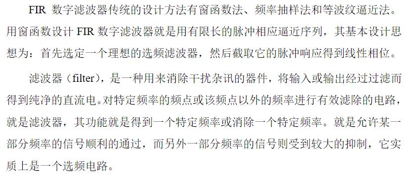
1.1 滤波器概念
1.2 数字滤波器的系统函数和差分方程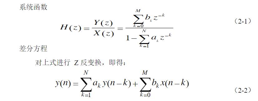
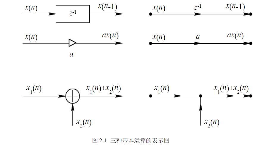
1.3 数字滤波器结构的表示
1.4 数字滤波器的分类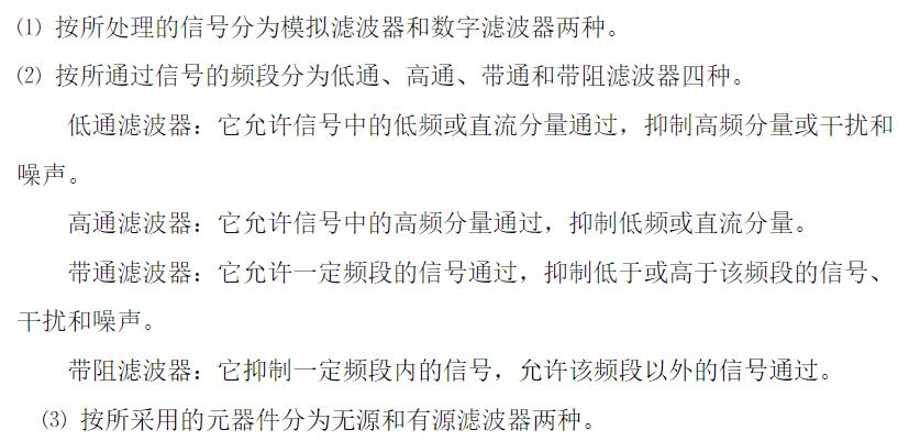

2.1 IIR滤波器与FIR滤波器的分析比较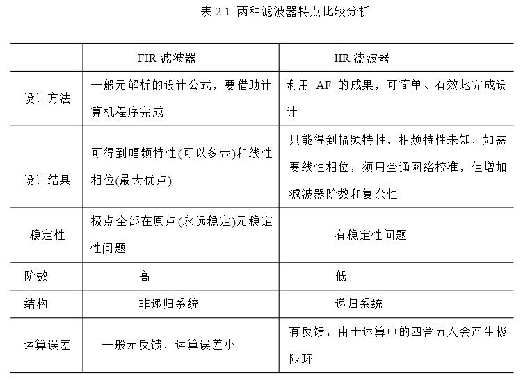
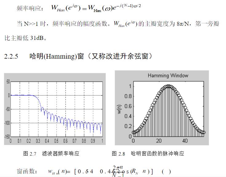
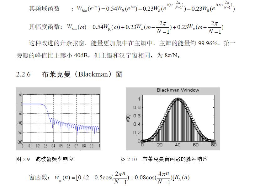
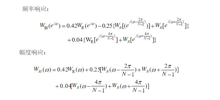
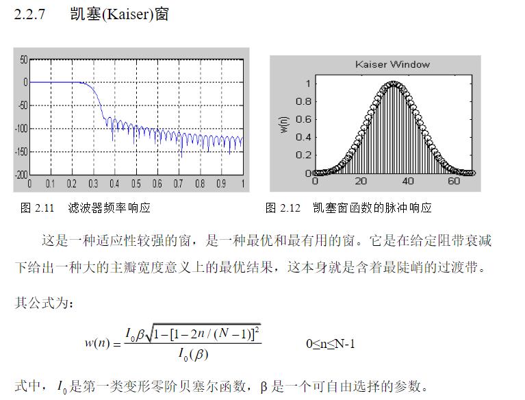
2.2 FIR滤波器的原理
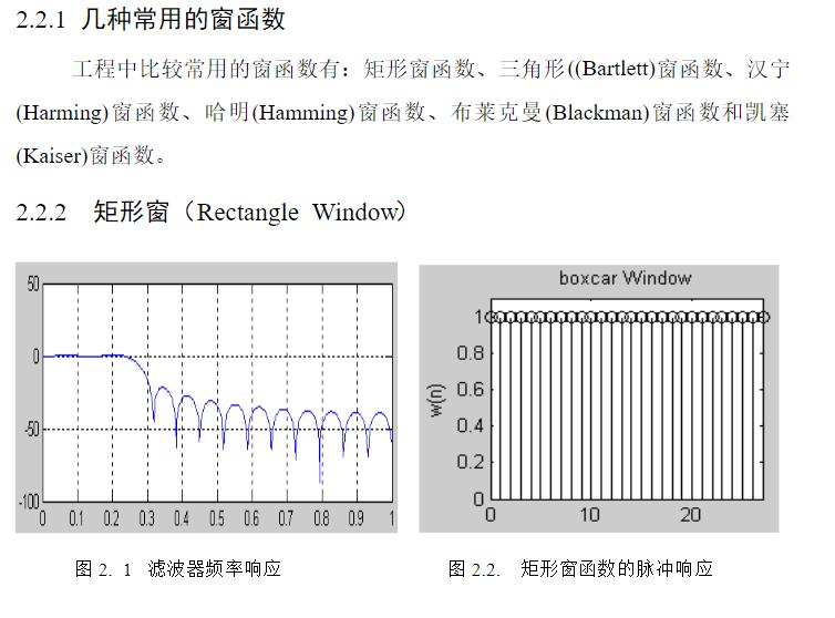
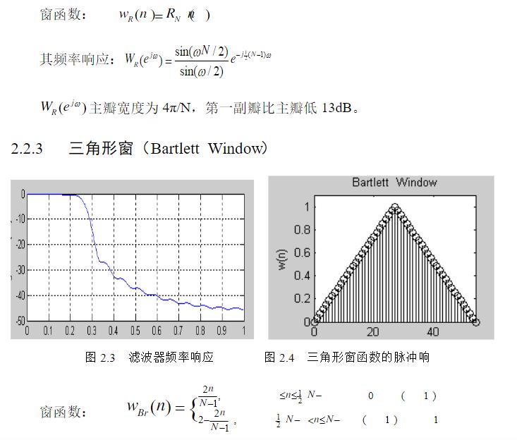
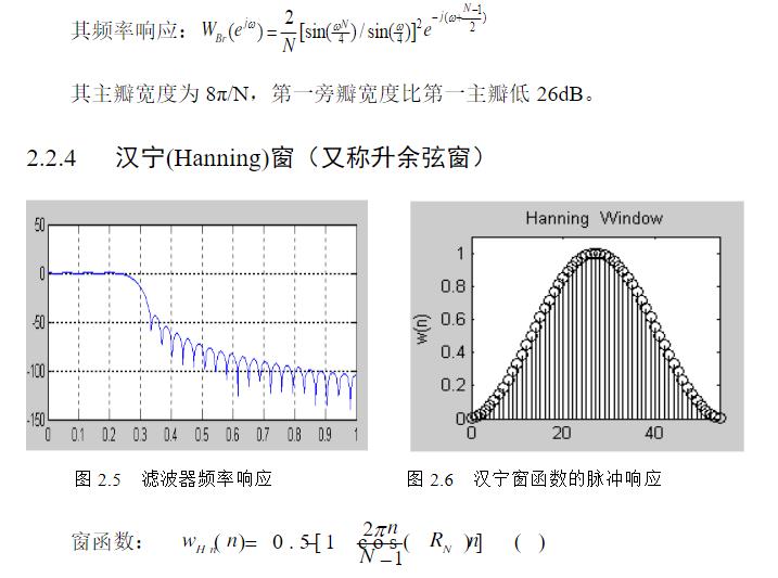
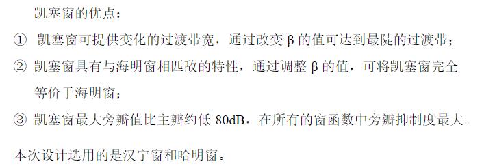
3 FIR滤波器的仿真步骤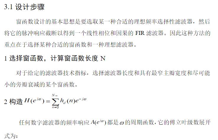
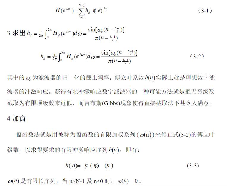
二、源代码
function varargout = nain1(varargin)
% NAIN1 MATLAB code for nain1.fig
%      NAIN1, by itself, creates a new NAIN1 or raises the existing
%      singleton*.
%
%      H = NAIN1 returns the handle to a new NAIN1 or the handle to
%      the existing singleton*.
%
%      NAIN1('CALLBACK',hObject,eventData,handles,...) calls the local
%      function named CALLBACK in NAIN1.M with the given input arguments.
%
%      NAIN1('Property','Value',...) creates a new NAIN1 or raises the
%      existing singleton*.  Starting from the left, property value pairs are
%      applied to the GUI before nain1_OpeningFcn gets called.  An
%      unrecognized property name or invalid value makes property application
%      stop.  All inputs are passed to nain1_OpeningFcn via varargin.
%
%      *See GUI Options on GUIDE's Tools menu.  Choose "GUI allows only one
%      instance to run (singleton)".
%
% See also: GUIDE, GUIDATA, GUIHANDLES

% Edit the above text to modify the response to help nain1

% Last Modified by GUIDE v2.5 07-Jan-2020 15:57:07

% Begin initialization code - DO NOT EDIT
gui_Singleton = 1;
gui_State = struct('gui_Name',       mfilename, ...
                   'gui_Singleton',  gui_Singleton, ...
                   'gui_OpeningFcn', @nain1_OpeningFcn, ...
                   'gui_OutputFcn',  @nain1_OutputFcn, ...
                   'gui_LayoutFcn',  [] , ...
                   'gui_Callback',   []);
if nargin && ischar(varargin{1})
    gui_State.gui_Callback = str2func(varargin{1});
end

if nargout
    [varargout{1:nargout}] = gui_mainfcn(gui_State, varargin{:});
else
    gui_mainfcn(gui_State, varargin{:});
end
% End initialization code - DO NOT EDIT


% --- Executes just before nain1 is made visible.
function nain1_OpeningFcn(hObject, eventdata, handles, varargin)
% This function has no output args, see OutputFcn.
% hObject    handle to figure
% eventdata  reserved - to be defined in a future version of MATLAB
% handles    structure with handles and user data (see GUIDATA)
% varargin   command line arguments to nain1 (see VARARGIN)

% Choose default command line output for nain1
handles.output = hObject;

% Update handles structure
guidata(hObject, handles);

% UIWAIT makes nain1 wait for user response (see UIRESUME)
% uiwait(handles.figure1);


% --- Outputs from this function are returned to the command line.
function varargout = nain1_OutputFcn(hObject, eventdata, handles)
% varargout  cell array for returning output args (see VARARGOUT);
% hObject    handle to figure
% eventdata  reserved - to be defined in a future version of MATLAB
% handles    structure with handles and user data (see GUIDATA)

% Get default command line output from handles structure
varargout{1} = handles.output;


% --- Executes on button press in pushbutton1.
function pushbutton1_Callback(hObject, eventdata, handles)
% hObject    handle to pushbutton1 (see GCBO)
% eventdata  reserved - to be defined in a future version of MATLAB
% handles    structure with handles and user data (see GUIDATA)
Fs = 1500;
t = 1:1/Fs:6;
t=t(1:5000);
%写入chirp.wav文件
[pyr1,fs]=audioread('1.wav');%声音读取
pyr=pyr1(1:5000);
n=length(pyr);
pyr1=fft(pyr,n); %快速傅里叶变换
f=Fs*(0:n/2 - 1)/n;

noise1=0.1*sin(20*pi*t);%低频噪声
x1=pyr+noise1;%加低频噪声信号
n=length(t); %画出加噪之后,其时域频域
S=abs(fft(pyr));%原始信号傅里叶变换
y1=abs(fft(x1));%原始信号傅里叶变换
handles.axes1;
subplot(121);
plot(pyr);
xlabel('时间');
ylabel('幅度');
title('原始信号波形'); %绘出时域波
subplot(122)
plot(S((1:length(S)/2)));
xlabel('频率');
ylabel('幅度');
title('原始信号频谱');
%% IIR频率变换法
%% 双线性变换法
% 2.1低通
Rp=3;%通带最大衰减dB
Rs=10;%阻带最小衰减dB
Wp=1000;%通带截止频率
Ws=1200;%阻带截止频率
[N,wn]=buttord(Wp,Ws,Rp,Rs,'s');
[b,a,k]=buttap(N);
[A,B,C,D]=zp2ss(b,a,k);
[A,B,C,D]=lp2lp(A,B,C,D,wn);%type='底通';
[b,a]=ss2tf(A,B,C,D);
[b21,a21]=bilinear(b,a,Fs);
[h21,w21]=freqz(b21,a21);         %根据参数求出频率响应
x21=filter(b21,a21,x1); % 进行低通滤波
y21=abs(fft(x21));  % 对滤波后信号做len点FFT变换
%2.3 切比雪夫I型滤波器 高通
Rp2=2;%通带最大衰减dB
Rs2=20;%阻带最小衰减dB
Wp2=3000;%通带截止频率
Ws2=3200;%阻带截止频率
[N,wn]=cheb1ord(Wp2,Ws2,Rp2,Rs2,'s');%求模拟的低通滤波器阶数和截止频率
[b,a,k]=cheb1ap(N,Rp2); %求S域的频率响应的参数
[A,B,C,D]=zp2ss(b,a,k);%阻带截止频率
[A,B,C,D]=lp2hp(A,B,C,D,wn);%type='高通';
[b,a]=ss2tf(A,B,C,D);%状态方程向传递函数转变
[b23,a23]=bilinear(b,a,Fs);%利用双线性变换实现S域到Z域转换
[h23,w23]=freqz(b23,a23);
x23=filter(b23,a23,x1); % 进行稿通滤波
y23=abs(fft(x23));  % 对滤波后信号做len点FFT变换
% 带通滤波器
Rp3=1;
Rs3=100;
Wp1=1200;
Ws1=1000;
Wp2=3000;
Ws2=3200;
Wp3=[Wp1,Wp2];
Ws3=[Ws1,Ws2];
%wp和ws分别是通带和阻带的频率(截止频率)。当wp和ws为二元矢量时,为带通或带阻滤波器,这时求出的Wn也是二元矢量;当wp和ws为一元矢量时,为低通或高通滤波器:当wp<ws时为低通滤波器,当wp>ws时为高通滤波器。
%wp和ws为二元矢量
Wp3=[1200 3000];                %设置通带频率
Ws3=[1000 3200];                %设置阻带频率
Rp3=1;                                   %设置通带波纹系数
Rs3=20;                                  %设置阻带波纹系数
[N,wn]=buttord(Wp3,Ws3,Rp3,Rs3,'s');
[b,a,k]=buttap(N);
[A,B,C,D]=zp2ss(b,a,k);
Wn=Wp2-Wp1;
Wo=sqrt(Wp2*Wp1);
[A,B,C,D]=lp2bp(A,B,C,D,Wo,Wn);% type='带通';
[num22,den22]=ss2tf(A,B,C,D);
% [b,a]=impinvar(num23,den23,Fs);
[b22,a22]=bilinear(num22,den22,Fs);%双线性变换实现S域到Z域的转换
[h22,w22]=freqz(b22,a22);                  %根据参数求出频率响应
x22=filter(b22,a22,x1); % 进行低通滤波
y22=abs(fft(x22));  % 对滤波后信号做len点FFT变换

%% FIR窗函数
% 3.1 低通滤波器
%该函数采用hanning窗实现低通滤波
fp=1000;%通带截止频率
fs=2000;%阻带起始频率
FS=8000;
wp=2*pi*fp/FS;%将模拟通带截止频率转换为数字滤波器频率
ws=2*pi*fs/FS;%将模拟阻带起始频率转换为数字滤波器频率
wn=(wp+ws)/2/pi;%标准化的截止频率响应
Bt=ws-wp;
N0=ceil(6.2*pi/Bt);%滤波器长度
N=N0+mod(N0+1,2);
%设计加窗函数fir1
[b31,a31]=fir1(N-1,wn,hanning(N));
[h31,w31]=freqz(b31,a31,FS);                     %得到频率响应
x31=filter(b31,a31,x1); % 进行低通滤波
y31=abs(fft(x31));  % 对滤波后信号做len点FFT变换

% 3.2 通带滤波
Fs=8000;
fp1=1200;%通带下限截止频率
fp2=3000;%通带上限截止频率
fs1=1000;
fs2=3200;
wp1=2*pi*fp1/Fs;%将通带下限截止频率转换为数字滤波器频率
wp2=2*pi*fp2/Fs;%将通带上限截止频率转换为数字滤波器频率
ws1=2*pi*fs1/Fs;%将通带下限截止频率转换为数字滤波器频率
ws2=2*pi*fs2/Fs;%将通带上限截止频率转换为数字滤波器频率
Bt=wp1-ws1;
N0=ceil(6.2*pi/Bt);
N=N0+mod(N0+1,2);
wn=[(wp1+ws1)/2/pi,(wp2+ws2)/2/pi];
%设计加窗函数fir1
[b32,a32]=fir1(N-1,wn,'bandpass',hanning(N));
%求滤波器的幅频响应
[h32,w32]=freqz(b32,a32,FS);
x32=filter(b32,a32,x1);
y32=abs(fft(x32));  % 对滤波后信号做len点FFT变换
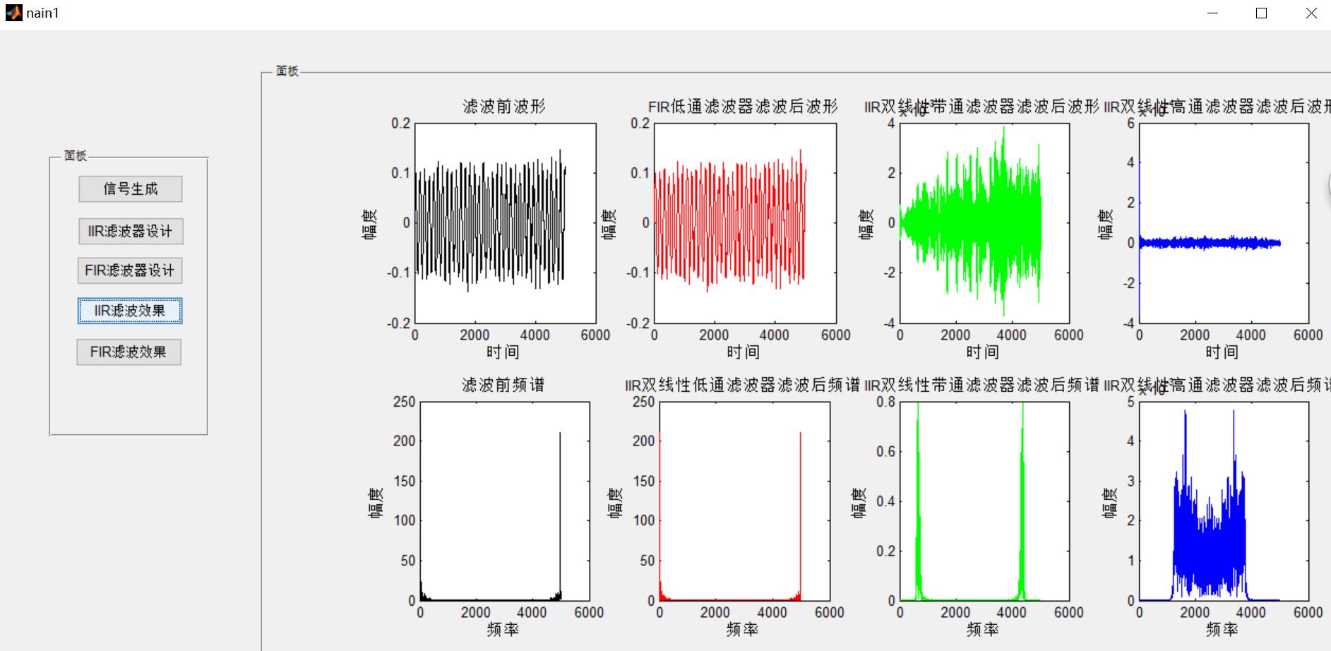
三、运行结果
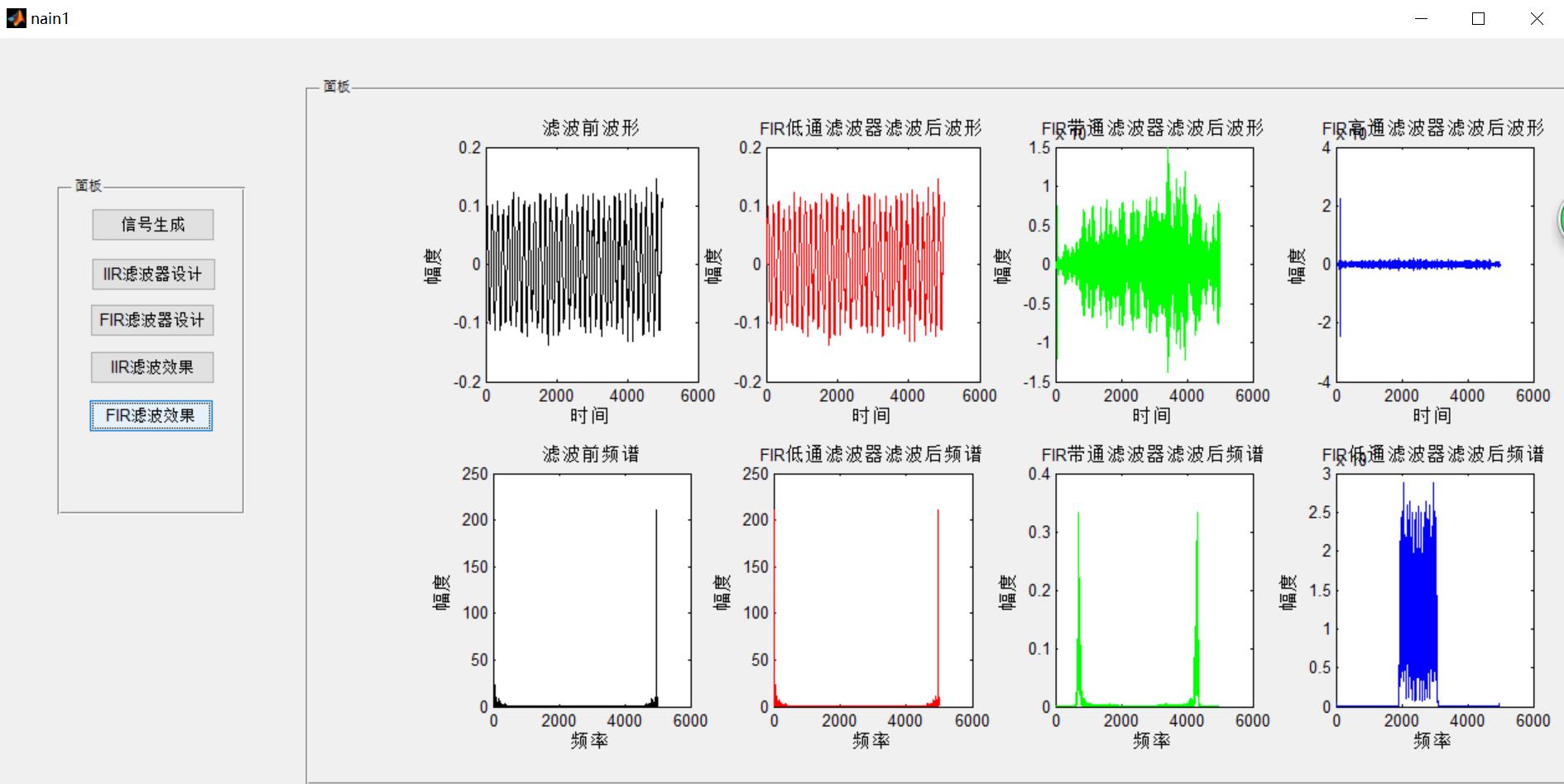
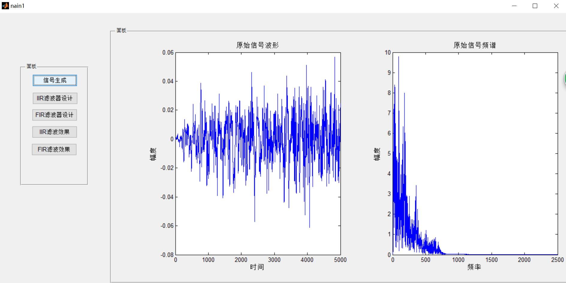
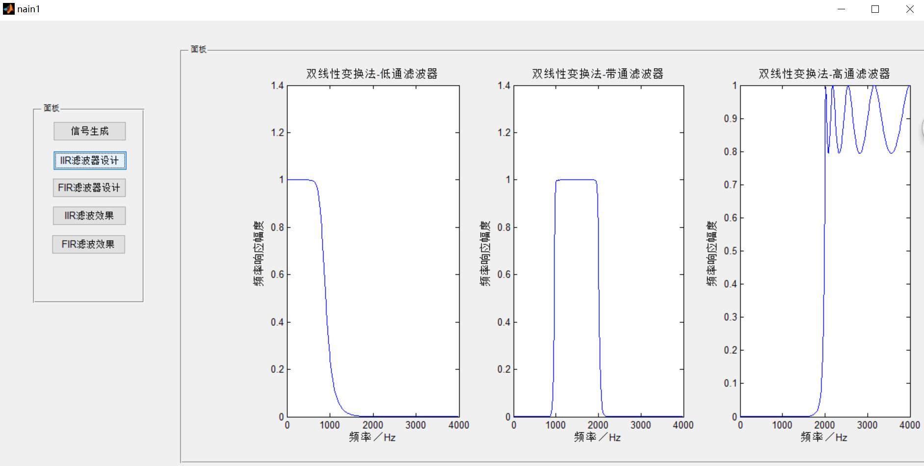
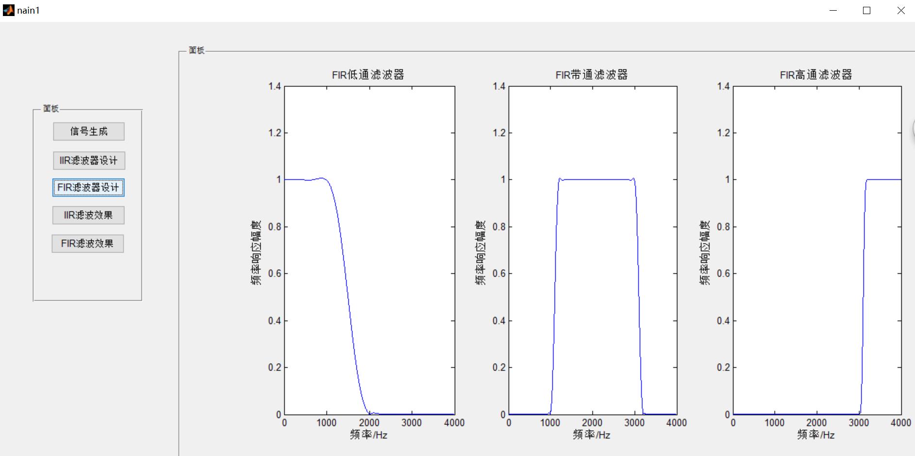
四、备注
完整代码或者仿真咨询添加QQ1575304183
以上是关于信号处理基于 FIR与IIR滤波器低通高通带通设计matlab源码含GUI的主要内容,如果未能解决你的问题,请参考以下文章