Waymo dataset+mmdet3d的坐标系问题
Posted ZLTJohn
tags:
篇首语:本文由小常识网(cha138.com)小编为大家整理,主要介绍了Waymo dataset+mmdet3d的坐标系问题相关的知识,希望对你有一定的参考价值。
mmdet3d 在处理 waymo dataset的时候,3D/2D gt box, point cloud等数据进行了非常多的坐标系转换。本身waymo的坐标系也有不少。
写这篇文章的motivation主要是,自己在处理3D point投影到2D image的过程中产生了两个问题:
- 枚举ego centric 3D点投到5个相机的时候,发现覆盖范围是歪的,front camera没有正对前方;别人的方法如CMKD,BEV range都是正的
- 使用同样的投影矩阵,将3D gt box的center投到相机时,pixel坐标和waymo给的projected laser label中的坐标不一致。
最后1是因为u,v弄反了,2是因为waym的projected 2d box,是最小的,能够框住所有lidar points in 3D box 的矩形,所以3D 和 2D gt box的center没有对应关系。
现在总结一下waymo dataset的坐标系,以及mmdet3d是如何转换waymo坐标系的。其中最为重要的,还是gt labels前后的坐标变化。
waymo dataset coordinate system
首先得说一下waymo dataset的结构。以training split为例,有700多个tfrecord文件,每个文件对应一个scene,是长度为20s左右的视频,大概有200帧,每帧有lidar和camera的数据,还有gt labels。
一帧对应一个Frame的protobuf类,具体的描述在waymo dataset项目的dataset.proto里。
global frame(coordinate)
对于一个scene,我们首先有一个预设的全局坐标系,global frame坐标系在ego运动之前就设定好了,z轴背对地心,x轴向东,y轴向北。车在global frame里移动,位姿由Frame.pose给出,是一个4x4的转移矩阵T,即齐次坐标下的旋转加位移[R,t]。
vehicle frame(coordinate)
车坐标系,ego-centric的坐标系,原点固定于车的某个点上,x轴向前,y轴向左,z轴向上。可以说,车的位姿,和这个坐标系是绑定的。当要计算不同frame间点的相对关系,我们可以利用Frame.pose,把点都转到global frame下进行计算。注意到,这里的T是vehicle转global的矩阵,用法是 p t g l o b a l = T × p t v e h i c l e , p t v e h i c l e = [ x , y , z , 1 ] T pt_global=T\\times pt_vehicle, pt_vehicle=[x,y,z,1]^T ptglobal=T×ptvehicle,ptvehicle=[x,y,z,1]T。
sensor frame
vehicle上装了许多sensor,每个sensor的位姿,对于每个scene来说是固定的。类似于frame.pose,每个sensor的位姿,或者说“外参”,都定义在vehicle坐标系下,同样有T=[R,t]。其中位移t在不同帧之间似乎是一致的(仅观察了部分top lidar的t),R有轻微不同。top lidar的转移矩阵(外参)记录在frames[0].context.laser_calibrations[0].extrinsic.transform中,意义为top lidar转移到vehicle坐标系的转移矩阵,其他的sensor类似。
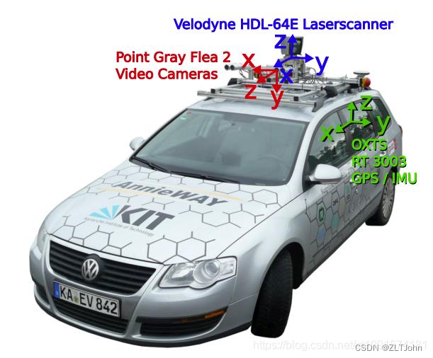
每个sensor的坐标系,其x,y,z轴如下图所示,sensor的位姿定义了其坐标系。

top lidar和front camera的坐标轴朝向基本和vehicle一致,只是有些位移,那么可以猜测其外参矩阵[R,t]中的R,大概为对角阵,而不同帧之间的外参应该基本相同(常理来说sensor的位置固定)。
比如validation set的scene_id=50(0开始计)的top lidar和front cam的外参如下
lidar2vehicle = np.array(frames[0].context.laser_calibrations[0].extrinsic.transform).reshape(4,4)
print(lidar2frame)
[[ 0.99991058  0.01128794  0.0071704   4.07      ]
 [-0.01139378  0.99982415  0.01489488  0.        ]
 [-0.00700101 -0.01497524  0.99986335  0.691     ]
 [ 0.          0.          0.          1.        ]]

cam2vehicle = print(np.array(frames[0].context.camera_calibrations[0].extrinsic.transform).reshape(4,4))
 [[ 9.99995305e-01 -2.01245736e-03 -2.31088635e-03  1.54387781e+00]
 [ 2.02892342e-03  9.99972413e-01  7.14533287e-03 -2.38738487e-02]
 [ 2.29644292e-03 -7.14998793e-03  9.99971802e-01  2.11539785e+00]
 [ 0.00000000e+00  0.00000000e+00  0.00000000e+00  1.00000000e+00]]
考虑lidar sensor中心,pt_lidar = [0,0,0,1], lidar2vehicle @ pt_lidar = [4,0,0.7,1]
考虑camera中心,pt_cam = [0,0,0,1], cam2vehicle @ pt_cam = [1.5, 0, 2.1, 1]
也就是说,top lidar相对于vehicle原点来说更靠前,而front cam更高。这基本也和上面的图长得一样。
Image frame(像素坐标系)
基础知识:一文带你搞懂相机内参外参(Intrinsics & Extrinsics)
相机坐标系已经由相机外参定义了(这里的定义指该坐标系下所有的数据,可以转换到前面说的任何坐标系下),像素坐标系则由相机内参进一步确定下来,坐标轴的设置和正常的一样,即图片左上角是原点,y轴向下,x轴向右。观察一下val_scene_id=30的front cam内参:
print(np.array(frames[0].context.camera_calibrations[0].intrinsic))
#// 1d Array of [f_u, f_v, c_u, c_v, k1, 2, p1, 2, k3].
[ 2.08052597e+03  2.08052597e+03  9.61318374e+02  6.45682293e+02
  4.20906774e-02 -3.47741413e-01  2.16363084e-03 -1.40652749e-04
  0.00000000e+00]
其中前四个内参矩阵K的参数,后面5个是去畸变的参数,定义与opencv的定义保持一致。修正的公式如下图。


相机坐标系下点pt(x,y,z)投影到像素坐标:
pt_2d = K@pt
x,y,_ = pt_2d/pt_2d.z
common camera coordinate && waymo camera sensor frame
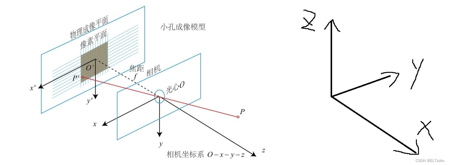
值得注意的是,一般我们考虑使用pt_2d= K@pt的时候,相机坐标系都是如左下方式定义的,但waymo却是以右下方式定义相机坐标系。所以,如果一个点waymo camera坐标系下的点pt_old(x0,y0,z0)要变换到image上,那要先做一个变换变成pt_new(-y0,-z0,x0),再用pt_2d = K @ pt_new得到真正的坐标。这点在后面mmdet3d转换坐标的时候也有体现。

The LiDAR Spherical coordinate system
lidar的球坐标系比较简单,原点和坐标轴都和lidar sensor坐标系重合。就是把(x,y,z)换成(r,θ,φ)。
接下来按程序执行顺序,介绍一下和坐标系相关的数据是怎样被处理的。
mmdet3d数据转换: waymo to kitti
分为两部分,第一部分是从tfrecord中读取信息,每帧整理成单个文件,第二部分是把所有帧的信息汇总为pkl。
waymo_converter.py
这个py文件遍历每个tfrecord的每个frame,做下面的操作:
self.save_image(frame, file_idx, frame_idx),只储存图片,不涉及坐标转换。
self.save_calib(frame, file_idx, frame_idx),储存外参,做一些变换
self.save_lidar(frame, file_idx, frame_idx),把lidar的range image存成point cloud,坐标基于vehicle坐标系
self.save_pose(frame, file_idx, frame_idx),把frame.pose存下来
self.save_timestamp(frame, file_idx, frame_idx),把frame.timestamp_micros存下来
self.save_label(frame, file_idx, frame_idx)
save_calib
这个函数最终会给pkl带去三种矩阵:P0 ~ 4, R0_rect, Tr_velo_to_cam0 ~ 4
R0_rect是kitti中的旋转校正矩阵,waymo里没用,定义为单位阵。
P0~4是相机内参矩阵K,只包含[f_u, f_v, c_u, c_v],没有去畸变参数,估计waymo给的图片已经是去过畸变的了。
Tr_velo_to_cam0~4是调整过的外参,某个Tr_velo_to_cam,计算方式如下
# waymo front camera to kitti reference camera
T_front_cam_to_ref = np.array([[0.0, -1.0, 0.0], [0.0, 0.0, -1.0],[1.0, 0.0, 0.0]])
vehicle2cam = np.linalg.inv(cam2vehicle)
Tr_velo_to_cam	= homo(T_front_cam_to_ref) @ vehicle2cam
其中homo()是把3x3的矩阵转换到4x4的齐次坐标系下,其中matrix[4,4]=1,其他多出来的位置置为0。T_front_cam_to_ref 是waymo camera 转kitti camera ,也就是把waymo camera坐标系转换成我们常用的相机坐标系,方便之后使用内参。其实我很奇怪为什么要叫’velo’ to cam,可能是kitti数据集里,vehicle pose定义为lidar pose了吧。事实上这里的Tr_velo_to_cam就是vehicle2kitticam。

save_lidar
把lidar的range image存成point cloud,坐标基于vehicle frame。
原本的range image应该是定义在 LiDAR Spherical coordinate system内的,每个像素(u,v)的θ和φ都能通过给定的参数算出。
range image除了有基本的range, intensity, elongation,还有“range_image_pose”,记录了每个pixel在采集的时刻,vehicle frame到global frame的transformation,用 [roll, pitch, yaw, x, y, z] 表示。
在转换成point cloud的时候,对于每个pixel,我们先根据range_image_pose以及pixel的(u,v,range),将pixel坐标转换成global frame的坐标,然后再使用vehicle pose,转换回vehicle坐标。
为什么要这么麻烦?直接用每个pixel的(u,v,range),从球坐标转成(x,y,z)不行吗?
我的理解是,waymo认为每个range image pixel对应的点,采集的时刻是不同的,所以对应的坐标系不同,他要把每个点的坐标系统一,所以记录了每个点在采集时刻的坐标系。
关于dataset内容的其他信息,之后再写一篇整理一下,这里主要关注的是坐标变换。
save_label
原本储存在tfrecord里的所有label,均是在vehicle坐标系下的,由frame.pose给出。
原先的gt object转换到kitti格式下,由location, dimensions, rotation_y, name, bbox构成,分别代表kitti camera坐标系下的3d box bottom center,3d box size,-frame.obj[i].camera_synced_box.heading - np.pi / 2, 物体class name, 2d box(frame.projected_lidar_labels中的box)。
具体地,box center转换到location的过程:x,y,z首先从gravity center变成了bottom center,然后pt = Tr_velo_to_cam[0] @ pt,即从waymo当前frame的vehicle坐标系,变换到kitti camera sensor坐标系下,原点对应waymo front camera,但是坐标轴有所不同。如下图。

前三个域共计7个量,构成了mmdet3d中的CameraInstance3DBoxes类。
总结一下,point cloud是位于vehicle坐标系下的,label是位于kitti front cam坐标系下的
kitti_data_utils.WaymoInfoGatherer
这块没有涉及坐标系转换,不过把calib里原本33或者34的矩阵都扩展成了4*4的矩阵。而且只把Tr_velo_to_cam0收集到info.pkl中,要做环视的detection还需要自己去kitti_format/training/calib/文件夹下读入1~4。
读入waymo dataset
这一块也是两部分,第一部分是waymodataset类读取info并送给到数据处理pipeline;第二部分是pipeline把数据处理成input tensor+img_metas。
waymodataset.get_data_info
这里计算出了我们之后要使用的lidar2img0~4,lidar2img[i] = P[i] @ R0_rect @ Tr_velo_to_cam[i],实际上就是 vehicle2img。这个转移矩阵非常关键,我们之后涉及的所有3D点都会通过这个矩阵,投影到相机上。对于一个vehicle坐标系下的点pt(x,y,z),假设投影到front cam,我们有
pt_2d = lidar2img[0]@ [x,y,z,1]
x,y,_ = pt_2d/pt_2d.z
这里其实涉及了非常多的坐标系转换,分步骤来看如下:
pt_2d = kitticam2img @ waymocam2kitticam @ vehicle2waymocam @ [x,y,z,1]
从右往左看,首先vehicle坐标系转换到waymo camera 坐标系,然后转换到kitti或者说我们普遍使用的camera坐标系,然后这样才能用内参P[i]转换到image坐标系。
dataset.get_anno_info
这个函数对2D gt labels没有任何修改。
这个函数继承了kitti_dataset.py的get_anno_info,对3D gt labels进行了变换,从CameraInstance3DBoxes,变成LiDARInstance3DBoxes。具体地:
rect = info['calib']['R0_rect'].astype(np.float32)
Trv2c = info['calib']['Tr_velo_to_cam'].astype(np.float32)
loc = annos['location']
dims = annos['dimensions']
rots = annos['rotation_y']
gt_names = annos['name']
gt_bboxes_3d = np.concatenate([loc, dims, rots[..., np.newaxis]],
                              axis=1).astype(np.float32)
#self.box_mode_3d = 'LIDAR'
gt_bboxes_3d = CameraInstance3DBoxes(gt_bboxes_3d).convert_to(
            self.box_mode_3d, np.linalg.inv(rect @ Trv2c))
具体的变换位于mmdet3d\\core\\bbox\\structures\\box_3d_mode.py的convert函数中:
偏转角rotation_y的变换:yaw = -yaw - np.pi / 2,等于是变回原来tfrecord里的偏转角了(waymo叫heading)。
3d box size仍然是没有变换,这里被称作xyz_size。
location用np.linalg.inv(rect @ Trv2c)变换回去了,即T = kitticam2vehicle,具体操作是:xyz = extended_xyz @ rt_mat.t()
最后重新打包起来,可以看到其他域是没有变的,被remains变量传递:
remains = arr[..., 7:] # arr 为输入进去的CameraInstance3DBoxes
return_arr = torch.cat([xyz[..., :3], xyz_size, yaw, remains], dim=-1)
最后转换好的3d gt labels放在info[‘anno_info’][‘gt_bboxes_3d’]下,经过pipeline后放在info[‘gt_bboxes_3d’]下。
所以搞了半天,label变来变去又变回原来的vehicle坐标系了,除了center从gravity center变成了bottom center,没有其他改变,实现得很丑。
pipeline
如果对image进行了rescale,那么其实我们要改一下lidar2img,比如在RandomScaleImageMultiViewImage中,如果有scale_factor = [fx,fy],那么我们就要:
scale_mat = [[fx,0,0,0],[0,fy,0,0],[0,0,1,0],[0,0,0,1]]
lidar2img = lidar2img @ scale_mat
在detr3d-waymo中,我没有这样rescale lidar2img,其实最好这样做一下。
另外在pad image的时候,按理说lidar2img也需要做修改,因为原来的(u,v)现在到了(u+pad,v+pad),不过这里也没有修改,不知道问题大不大?
detr3d的training:forward与loss
这一块主要聚焦gt labels如何作为target,以及reference point的生成。
loss
dataset类的输出经过pipeline后,最终也形成一个dict类,送给模型,模型直接解析里面每个key。
detr3d detector,把gt_bboxes_3d直接送入loss计算
    def forward_pts_train(self,
                          pts_feats,
                          gt_bboxes_3d,
                          gt_labels_3d,
                          img_metas,
                          gt_bboxes_ignore=None):
        outs = self.pts_bbox_head(pts_feats, img_metas)
        loss_inputs = [gt_bboxes_3d, gt_labels_3d, outs]
        losses = self.pts_bbox_head.loss(*loss_inputs)
在detr3d_head.loss的一开始,就把gt box的center从bottom center变成了gravity center。这下完全和protobuf里的一样了。
gt_bboxes_list = [torch.cat(
            (gt_bboxes.gravity_center, gt_bboxes.tensor[:, 3:]),        # turn bottm center into gravity center, key step
            dim=1).to(device) for gt_bboxes in gt_bboxes_list]
gt_bboxes_list在为每层transformer的每个query output分配之后,转换成bbox_targets_list,此时数值上还没有变化。
再之后就要做归一化:
#   normalized_bbox_targets = normalize_bbox(bbox_targets, self.pc_range)
	cx = bboxes[..., 0:1]
    cy = bboxes[..., 1:2]
    cz = bboxes[..., 2:3]
    w = bboxes[..., 3:4].log()
    l = bboxes[..., 4:5].log()
    h = bboxes[..., 5:6].log()
    rot = bboxes[..., 6:7]
    rs = rot.sin()
    rc = rot.cos()
也就是中心点坐标并没有变化,只是box size做了常规的取log。
normalized_bbox_targets就是最终用来算loss的target
reference point
每层的每个query都会生成reference point。使用lidar2img矩阵投影到img上做feature sampling。所以这里的ref point坐标是在vehicle坐标系下的。
检查这里使用的lidar2img是否正确,比如使用这里的lidar2img,对gt和bbox prediction进行投影,就能确定之前所有的坐标系操作是不是bug free。
reference point首先生成一个归一化的BEV坐标,然后通过point cloud range转换到我们希望检测的perception range中。
一种生成方式是生成归一化的笛卡尔坐标,[0,1]x[0,1]x[0,1] -> [-75,75]x[-75,75]x[-2,4]。这样我们的感知空间是一个长方体。
还有一种生成方法是生成归一化的极坐标,[0,1]x[0,1]x[0,1] -> [0,75] x [θ_min, θ_max] x [-2,4]。这样我们的感知空间是一个扇柱。
这两种生成方式适用于gt labels 分布不同的数据集。
reference point由reg_branch生成,同时会生成box size, heading等变量。把reference point从归一化坐标变换到vehicle坐标系内,point就作为3d box center,和box size, heading(偏转角)一同构成模型的输出:3d box prediction
detr3d的evaluation与test
这个过程中,模型的输出做了许多格式和坐标系的调整,和之前处理gt labels一样,也是转换到kitti格式,又转回waymo vehicle坐标系,过程非常冗长。
detr3d的3d box prediction输出格式,和其target格式一致,那么在prediction转换为最终的bbox的时候,只需要:
    w = w.exp()
    l = l.exp()
    h = h.exp()
    rot = torch.atan2(rot_sine, rot_cosine)
之后这些 predicted boxes会经过NMSFreeCoder,筛掉中心点超出post_center_range的box,形成最终的输出。
目前,输出是位于vehicle坐标系下的3d box center, size, heading,称为output。
waymodataset.format_results第一步:转换output至kitti格式(坐标系)
output首先经过waymodataset.bbox2result_kitti,转换成和info.pkl里的gt labels一样的格式。其中box center和heading又要从vehicle坐标系转到kitti front camera坐标系。具体操作如下:
box_dict = self.convert_valid_bboxes(pred_dicts, info)  #用当前帧的Tr_velo_to_cam做变换
for box, box_lidar, bbox, score, label in zip(
                        box_preds, box_preds_lidar, box_2d_preds, scores,
                        label_preds):
                    bbox[2:] = np.minimum(bbox[2:], image_shape[::-1])
                    bbox[:2] = np.maximum(bbox[:2], [0, 0])
                    anno['name'].append(class_names[int(label)])
                    anno['truncated'].append(0.0)
                    anno['occluded'].append(0)
                    anno['alpha'].append(
                        -np.arctan2(-box_lidar[1], box_lidar[0]) + box[6])
                    anno['bbox'].append(bbox)
                    anno['dimensions'].append(box[3:6])
                    anno['location'].append(box[:3])
                    anno['rotation_y'].append(box[6])
                    anno['score'].append(score)
waymodataset.format_results第二步:从kitti转回waymo格式
我们的output是以frame为单位的,由于之前dataset转成kitti格式之后丢失了很多信息,我们首先需要遍历所有tfrecord,找到每个output对应哪个frame,然后整理成waymo所需的格式,其中所需信息如下:
for camera in frame.context.camera_calibrations:
            # FRONT = 1, see dataset.proto for details
            if camera.name == 1:
                T_front_cam_to_vehicle = np.array(
                    camera.extrinsic.transform).reshape(4, 4)
self.T_ref_to_front_cam = np.array([[0.0, 0.0, 1.0, 0.0],
                                    [-1.0, 0.0, 0.0, 0.0],
                                   	[0.0, -1.0, 0.0, 0.0],
                                    [0.0, 0.0, 0.0, 1.0]])
T_k2w = T_front_cam_to_vehicle @ self.T_ref_to_front_cam    # inverse(Tr_velo_to_cam)

info = 'filename': filename, 'T_k2w': T_k2w, 'context_name': context_name,\\
                    'frame_timestamp_micros': frame_timestamp_micros
可以看到T_k2w完全就是Tr_velo_to_cam。
有了info的信息,我们就可以把每个frame的output,从kitti整理成waymo用于evaluation和submission的格式了,其中涉及坐标变换的部分如下:
            # y: downwards; move box origin from bottom center (kitti) to grav center
            y -= height / 2
            # frame transformation: kitti -> waymo
            x, y, z = self.transform(T_k2w, x, y, z)

            # different conventions
            heading = -(rotation_y + np.pi / 2)
            while heading < -np.pi:
                heading += 2 * np.pi
            while heading > np.pi:
                heading -= 2 * np.pi
最终整理的格式可在waymo dataset项目的metrics.proto里找到,程序里整理的部分如下。其中field Label中,只需要整理field box即可
message Object
  optional Label object = 1;
  optional float score = 2 [default = 1.0];
  optional string context_name = 4;
  optional int64 frame_timestamp_micros = 5;
context_name和frame_timestamp_micros大可以先存在data_info.pkl里,就不需要在evaluation的阶段又读取tfrecord文件了。 先转成kitti格式,又放不开waymo格式的数据,两个都一起用,实现得很丑。
以上是关于Waymo dataset+mmdet3d的坐标系问题的主要内容,如果未能解决你的问题,请参考以下文章