ubuntu下安装运行电路仿真软件ngspice,打通KiCAD上手指南
Posted 海里的鱼2022
tags:
篇首语:本文由小常识网(cha138.com)小编为大家整理,主要介绍了ubuntu下安装运行电路仿真软件ngspice,打通KiCAD上手指南相关的知识,希望对你有一定的参考价值。
按流程一步一步上手,安装包和例子下载见:
https://download.csdn.net/download/pocean2012/85099820
1. 官网链接,信息很完整
上手指南
ngspice tutorial for beginners
2. 下载安装包:
Download ngspice from SourceForge.net
3. 解压到指定目录后,运行安装配置脚本,其实就是配置环境和进行编译。
sudo bash ./compile_linux.sh 64运行编译命令也行
./configure --with-x --enable-xspice --enable-cider --with-readline=yes --enable-openmp --disable-debug CFLAGS="-m64 -O2" LDFLAGS="-m64 -s"
make -j8
sudo make install 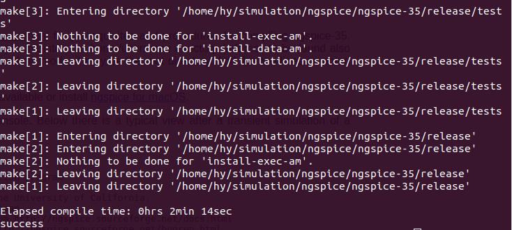
4. 编译成功,验证一下:

5. 跑个官方例子
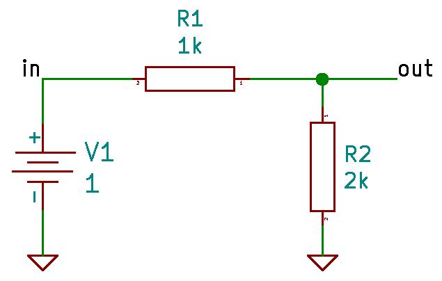
生成vdiv.cir文件
gedit vdiv.cir
voltage divider netlist
V1 in 0 1
R1 in out 1k
R2 out 0 2k
.end
保存退出
运行ngspice,调入文件,做dc仿真
******
** ngspice-35 : Circuit level simulation program
** The U. C. Berkeley CAD Group
** Copyright 1985-1994, Regents of the University of California.
** Copyright 2001-2020, The ngspice team.
** Please get your ngspice manual from http://ngspice.sourceforge.net/docs.html
** Please file your bug-reports at http://ngspice.sourceforge.net/bugrep.html
** Creation Date: Sat Apr  9 07:18:39 UTC 2022
******
ngspice 3 -> source vdiv.cir

No compatibility mode selected!


Circuit: voltage divider netlist

ngspice 4 -> op
Doing analysis at TEMP = 27.000000 and TNOM = 27.000000


No. of Data Rows : 1
ngspice 5 -> print out
out = 6.666667e-01
ngspice 6 ->
6. 再来个AC仿真的例子

上面的电路图可以在KICAD里画图,信号标签就是输入输出,文本标签就是仿真指令
编辑网表文件
.title dual rc ladder
R1 int in 10k
V1 in 0 dc 0 PULSE (0 5 1u 1u 1u 1 1)
R2 out int 1k
C1 int 0 1u
C2 out 0 100n
.end
运行加载,执行仿真指令,画图
ngspice 6 -> source rc1.cir

No compatibility mode selected!


Circuit: dual rc ladder

ngspice 7 -> tran 50u 50m
Doing analysis at TEMP = 27.000000 and TNOM = 27.000000


Initial Transient Solution
--------------------------

Node                                   Voltage
----                                   -------
int                                          0
in                                           0
out                                          0
v1#branch                                    0


No. of Data Rows : 1029
ngspice 8 -> plot in int out


x0 = 0.0234906, y0 = 0.298701

x0 = 0.0234906, y0 = 0.298701
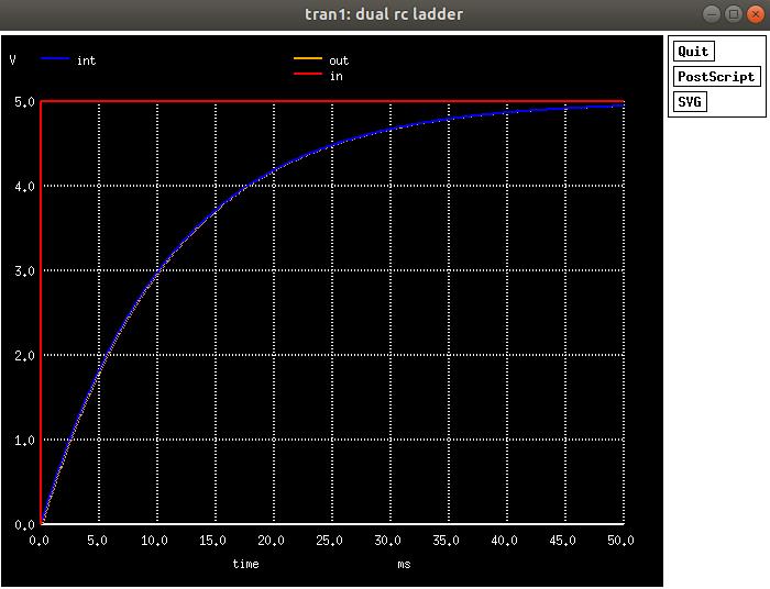
仿真输出电压波形
7. 在KICAD里完成上面的原理图绘制及仿真
官方指引
KiCad Eeschema as GUI for ngspice, tutorial for setting up the simulation
1)放置器件,注意,为了仿真模型确定性,选择spice库的标准器件

2)放置电阻,电容,电源,0地(必须)

3)连线,配置参数,加输入输出标签
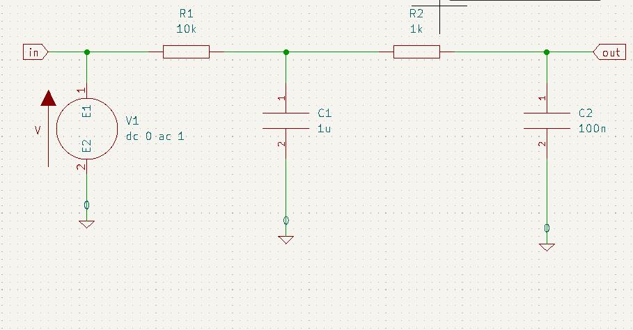
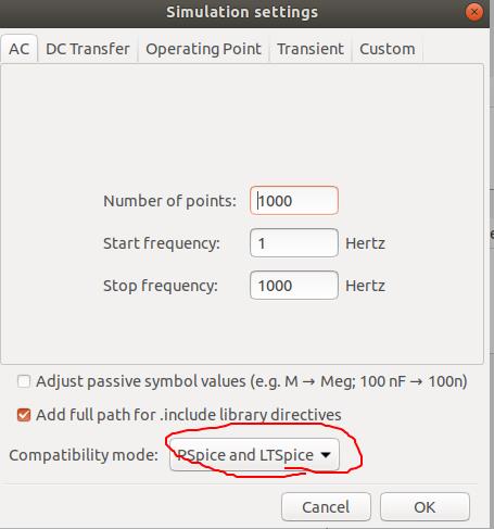
4)菜单inspect-->Simulator就可以打开仿真对话窗,如果灰色,需要在参数设置里选择
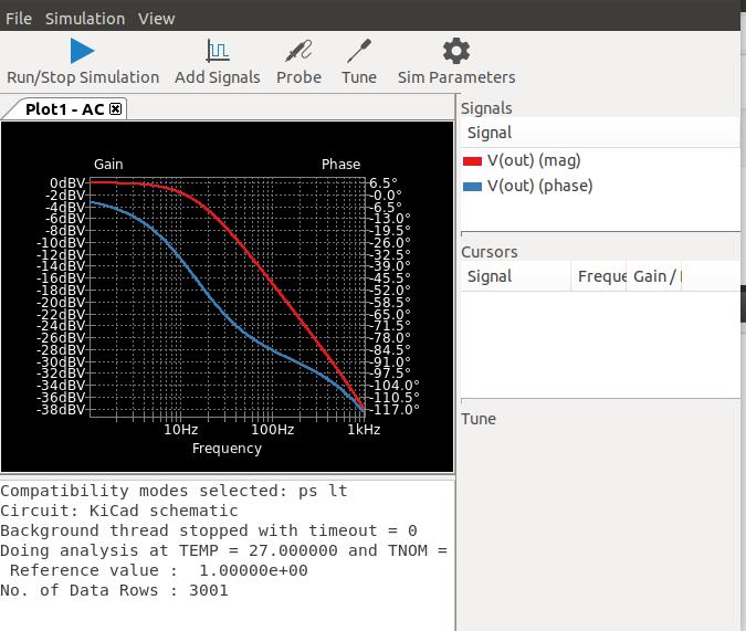
5)运行仿真,添加信号V(out)观察波形

6)仿真波形结果
7)改变输入信号, 变换仿真命令,观察变化
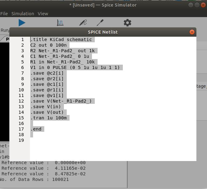
电压源 'dc 0 ac 1' 换成 'PULSE (0 5 1u 1u 1u 1 1)'

仿真命令 '.tran 1u 100m'.

运行仿真后,可以查看更新的网表文件
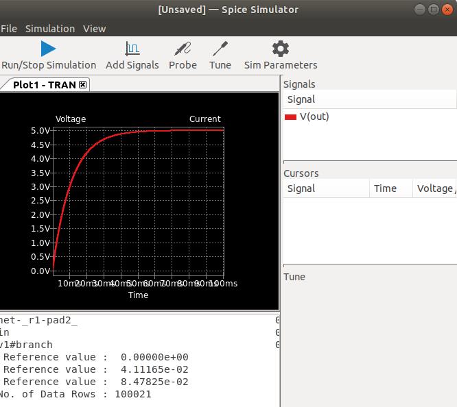
观察波形变化
也可以保存网表后,加载仿真。
刚才网表另存为rc1.cir
目录下运行ngspice, 加载,仿真
ngspice 9 -> source rc1.cir

No compatibility mode selected!


Circuit: KiCad schematic


ngspice 13 -> tran 50u 50m
Doing analysis at TEMP = 27.000000 and TNOM = 27.000000

Warning: v1: no DC value, transient time 0 value used

Initial Transient Solution
--------------------------

Node                                   Voltage
----                                   -------
out                                          0
net-_r1-pad2_                                0
in                                           0
v1#branch                                    0


No. of Data Rows : 1029
ngspice 14 -> plot in int out
Error: no such vector int
ngspice 15 -> plot out
ngspice 16 ->
作图效果

至此,完成了ngspice安装,以及打通KICAD文件。
KICAD例子及网表见下载链接
以上是关于ubuntu下安装运行电路仿真软件ngspice,打通KiCAD上手指南的主要内容,如果未能解决你的问题,请参考以下文章