verilog双端口读写德ram怎么写
Posted
tags:
篇首语:本文由小常识网(cha138.com)小编为大家整理,主要介绍了verilog双端口读写德ram怎么写相关的知识,希望对你有一定的参考价值。
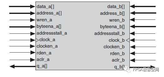
参考技术A verilog只能做一个双口读写RAM的model,可以用来仿真,不能用来综合的不然用register搭RAM面积太大了,真要用RAM还是要在综合的时候调双口RAM的libexample: RAM model,仅供仿真使用
module two_port_ram (
input clk,
input [7:0] wr_addr,
input [15:0] wr_data,
input wr_en,
input [7:0] rd_addr,
output reg [15:0] rd_data
);
reg [15:0] memory[256];
always @ (posedge clk)
if(wr_en)
memory[wr_addr] <= wr_data;
always @ (posedge clk)
rd_data<=memory[rd_addr];
endmodule本回答被提问者采纳
verilog实现之同步FIFO
上一节我们实现RAM的相关知识,也对比了RAM和FIFO的区别;FIFO:先进先出数据缓冲器,也是一个端口只读,另一个端口只写。但是FIFO与伪双口RAM的不同,FIFO为先入先出,没有地址线,不能对存储单元寻址;而伪双口RAM两个端口都有地址线,可以对存储单元寻址。但是FIFO内部的存储单元主要是由双口RAM(异步读写来实现的),在verilog 实现之RAM中已经讲过各种各样的RAM的实现。此时就要用双端口的RAM来实现FIFO。
一、实现双口RAM(异步读写)


  1 `timescale 1ns / 1ps
  2 //////////////////////////////////////////////////////////////////////////////////
  3 // Company:
  4 // Engineer:
  5 //
  6 // Create Date: 2020/06/25 20:46:14
  7 // Design Name:
  8 // Module Name: synram_double_port
  9 // Project Name:
 10 // Target Devices:
 11 // Tool Versions:
 12 // Description:
 13 //
 14 // Dependencies:
 15 //
 16 // Revision:
 17 // Revision 0.01 - File Created
 18 // Additional Comments:
 19 //
 20 //////////////////////////////////////////////////////////////////////////////////
 21
 22
 23 module synram_double_port #(
 24 parameter DATA_WIDTH = 8,
 25 parameter ADDR_WIDTH = 8,
 26 parameter RAM_DEPTH = 1 << ADDR_WIDTH
 27 )(
 28 input [ADDR_WIDTH - 1 : 0] address_0 , // address_0 Input
 29 inout [DATA_WIDTH-1 : 0] data_0    , // data_0 bi-directional
 30 input cs_0      , // Chip Select
 31 input we_0      , // Write Enable/Read Enable
 32 input oe_0      , // Output Enable
 33 input [ADDR_WIDTH - 1 : 0] address_1 , // address_1 Input
 34 inout [DATA_WIDTH-1 : 0] data_1    , // data_1 bi-directional
 35 input cs_1      , // Chip Select
 36 input we_1      , // Write Enable/Read Enable
 37 input oe_1        // Output Enable
 38 );
 39
 40 //--------------Internal variables----------------
 41 reg [DATA_WIDTH-1:0] data_0_out ;
 42 reg [DATA_WIDTH-1:0] data_1_out ;
 43 reg [DATA_WIDTH-1:0] mem [0:RAM_DEPTH-1];
 44
 45
 46 //initialization
 47
 48 // synopsys_translate_off
 49 integer i;
 50 initial begin
 51     for(i=0; i < RAM_DEPTH; i = i + 1) begin
 52         mem[i] = 8‘h00;
 53     end
 54 end
 55 // synopsys_translate_on
 56
 57
 58 //--------------Code Starts Here------------------
 59 // Memory Write Block
 60 // Write Operation : When we_0 = 1, cs_0 = 1
 61 always @ (address_0 or cs_0 or we_0 or data_0
 62 or address_1 or cs_1 or we_1 or data_1)
 63 begin : MEM_WRITE
 64   if ( cs_0 && we_0 ) begin
 65      mem[address_0] <= data_0;
 66   end
 67   else if  (cs_1 && we_1) begin
 68      mem[address_1] <= data_1;
 69   end
 70 end
 71
 72 // Tri-State Buffer control
 73 // output : When we_0 = 0, oe_0 = 1, cs_0 = 1
 74 assign data_0 = (cs_0 && oe_0 && !we_0) ? data_0_out : 8‘bz;
 75
 76 // Memory Read Block
 77 // Read Operation : When we_0 = 0, oe_0 = 1, cs_0 = 1
 78 always @ (address_0 or cs_0 or we_1 or oe_0)
 79 begin : MEM_READ_0
 80   if (cs_0 && !we_0 && oe_0) begin
 81     data_0_out <= mem[address_0];
 82   end else begin
 83     data_0_out <= 0;
 84   end
 85 end
 86
 87 //Second Port of RAM
 88 // Tri-State Buffer control
 89 // output : When we_0 = 0, oe_0 = 1, cs_0 = 1
 90 assign data_1 = (cs_1 && oe_1 && !we_1) ? data_1_out : 8‘bz;
 91 // Memory Read Block 1
 92 // Read Operation : When we_1 = 0, oe_1 = 1, cs_1 = 1
 93 always @ (address_1 or cs_1 or we_1 or oe_1)
 94 begin : MEM_READ_1
 95   if (cs_1 && !we_1 && oe_1) begin
 96     data_1_out <= mem[address_1];
 97   end else begin
 98     data_1_out <= 0;
 99   end
100 end
101
102 endmodule
二、对RAM端口的实例化
 1 synram_double_port #(
 2         .DATA_WIDTH(DATA_WIDTH),
 3         .ADDR_WIDTH(ADDR_WIDTH),
 4         .RAM_DEPTH(RAM_DEPTH)
 5     ) inst_synram_double_port (
 6         .address_0 (wr_pointer),
 7         .data_0    (data_in),
 8         .cs_0      (wr_cs),
 9         .we_0      (wr_en),
10         .oe_0      (1‘b0),
11         .address_1 (rd_pointer),
12         .data_1    (data_ram),
13         .cs_1      (rd_cs),
14         .we_1      (1‘b0),
15         .oe_1      (rd_en)
16     );
三、同步FIFO的实现
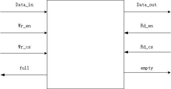
同步FIFO的框图:

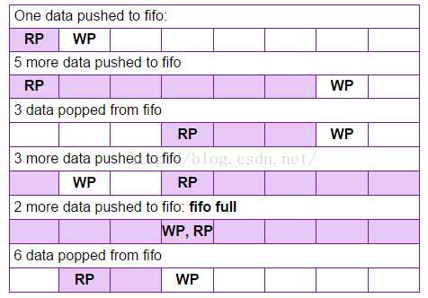
同步FIFO读写原理:通常,FIFO是使用旋转指针实现的。 我们可以将FIFO的写入和读取指针称为数据区的头和尾。 最初,FIFO的读写指针将指向相同的位置,吸入所示:这是一个解释FIFO如何使用内存的示例。 这是长度为8的fifo,WP和RP是写指针和读指针指向的位置。 图中的阴影区域填充了数据。使用stutus_cnt记录FIFO RAM中的数据个数,等于0时,给出empty信号,等于RAM_DEPTH时,给出full信号。stutus_cnt写而未满时增加1,读而未空时减1。同时发生读写操作时,stutus_cnt。读写指针宽度与地址宽度相当,地址增加而溢出后,自动变成0。

从同步FIFO的框图中。我们可以推理出同步FIFO的管脚图,同时这里所说的fifo 没有了地址,是因为用指针代替了地址。剩下的就是看图说话。

四、实现的代码
RTL:

1 `timescale 1ns / 1ps 2 ////////////////////////////////////////////////////////////////////////////////// 3 // Company: 4 // Engineer: 5 // 6 // Create Date: 2020/06/25 20:42:22 7 // Design Name: 8 // Module Name: syn_fifo 9 // Project Name: 10 // Target Devices: 11 // Tool Versions: 12 // Description: 13 // 14 // Dependencies: 15 // 16 // Revision: 17 // Revision 0.01 - File Created 18 // Additional Comments: 19 // 20 ////////////////////////////////////////////////////////////////////////////////// 21 22 module syn_fifo #( 23 parameter DATA_WIDTH = 8, 24 parameter ADDR_WIDTH = 8, 25 parameter RAM_DEPTH = (1 << ADDR_WIDTH) 26 ) 27 ( 28 input wire clk , 29 input wire rst , 30 //interfaces 31 input wire wr_cs ,//å†?--片é?‰ä¿¡å?? 32 input wire rd_cs ,//è¯?--片é?‰ä¿¡å?? 33 input wire [DATA_WIDTH-1:0] data_in ,//输入数æ?® 34 input wire rd_en ,//读是èƒ? 35 input wire wr_en ,//写使èƒ? 36 output wire [DATA_WIDTH-1:0] data_out ,//æ•°æ?®è¾“出 37 output wire empty ,//ç©ºæ ‡å¿? 38 output wire full 39 40 ); 41 42 //======================================================================== 43 // ################ Define Parameter and Internal signals ################ 44 //========================================================================/ 45 reg [ADDR_WIDTH-1:0] wr_pointer ;//写指é’? 46 reg [ADDR_WIDTH-1:0] rd_pointer ; 47 reg [ADDR_WIDTH:0] status_cnt ;//状æ?? 48 reg [DATA_WIDTH-1:0] data_out_r ;//æ•°æ?®è®¡æ•° 49 wire [DATA_WIDTH-1:0] data_ram ; 50 51 //============================================================================= 52 //+++++++++++++++++++++++++ Main Code +++++++++++++++++++++++++++++++ 53 //============================================================================= 54 55 assign full = (status_cnt==RAM_DEPTH)?1‘b1 :1‘b0 ; 56 assign empty = (status_cnt==0)?1‘b1:1‘b0; 57 58 //wr_pointer 59 always @(posedge clk or posedge rst) begin 60 if (!rst) begin 61 wr_pointer <= 0 ; 62 end 63 else if (wr_cs && wr_en) begin 64 wr_pointer <= wr_pointer + 1; 65 end 66 end 67 68 //rd_pointer 69 always @(posedge clk or posedge rst) begin 70 if (!rst) begin 71 rd_pointer <= 0 ; 72 end 73 else if (rd_cs && rd_en) begin 74 rd_pointer <= rd_pointer + 1‘b1 ; 75 end 76 end 77 //data_out_r 78 79 always @(posedge clk or posedge rst) begin 80 if (!rst) begin 81 data_out_r <= 0 ; 82 83 end 84 else if (rd_cs && rd_en) begin 85 data_out_r <= data_ram ; 86 end 87 end 88 assign data_out = data_out_r ; 89 90 //status_cnt 91 always @(posedge clk or posedge rst) begin 92 if (!rst) begin 93 94 status_cnt <= 0; //å?ªè¯»ä¸?写 95 end 96 else if ((rd_cs && rd_en) && !(wr_cs && wr_en) && (status_cnt!=0)) begin 97 status_cnt <= status_cnt - 1‘b1 ;//å?ªè¯»ä¸?写 98 end 99 else if(!(rd_cs && rd_en) && (wr_cs && wr_en) && (status_cnt!=RAM_DEPTH))begin 100 status_cnt <= status_cnt + 1‘b1 ;//å?ªå†™ä¸?读 101 end 102 end 103 104 105 106 synram_double_port #( 107 .DATA_WIDTH(DATA_WIDTH), 108 .ADDR_WIDTH(ADDR_WIDTH), 109 .RAM_DEPTH(RAM_DEPTH) 110 ) inst_synram_double_port ( 111 .address_0 (wr_pointer), 112 .data_0 (data_in), 113 .cs_0 (wr_cs), 114 .we_0 (wr_en), 115 .oe_0 (1‘b0), 116 .address_1 (rd_pointer), 117 .data_1 (data_ram), 118 .cs_1 (rd_cs), 119 .we_1 (1‘b0), 120 .oe_1 (rd_en) 121 ); 122 123 endmodule
TB:

  1 `timescale 1ns / 1ps
  2 //////////////////////////////////////////////////////////////////////////////////
  3 // Company:
  4 // Engineer:
  5 //
  6 // Create Date: 2020/06/25 23:12:58
  7 // Design Name:
  8 // Module Name: syn_fifo_tb
  9 // Project Name:
 10 // Target Devices:
 11 // Tool Versions:
 12 // Description:
 13 //
 14 // Dependencies:
 15 //
 16 // Revision:
 17 // Revision 0.01 - File Created
 18 // Additional Comments:
 19 //
 20 //////////////////////////////////////////////////////////////////////////////////
 21
 22
 23
 24 module syn_fifo_tb();
 25
 26 parameter DATA_WIDTH = 8;
 27 parameter ADDR_WIDTH = 8;
 28 parameter RAM_DEPTH = (1 << ADDR_WIDTH);
 29
 30 reg clk ;
 31 reg rst ;
 32 reg wr_cs ;
 33 reg rd_cs ;
 34 reg rd_en ;
 35 reg wr_en ;
 36 reg [DATA_WIDTH-1:0] data_in ;
 37 wire full ;
 38 wire empty ;
 39 wire [DATA_WIDTH-1:0] data_out ;
 40
 41
 42 initial begin
 43     clk = 0;
 44     forever
 45     #2 clk = ~clk;
 46
 47 end
 48
 49 integer i=0;
 50 initial begin
 51
 52     rst = 0;
 53     wr_cs = 0;
 54     rd_cs = 0;
 55     wr_en = 0;
 56     rd_en = 0;
 57     data_in = 0;
 58
 59     #8
 60     rst = 1;
 61     //write
 62     wr_cs = 1;
 63     wr_en = 1;
 64
 65     for(i = 0; i < 256; i = i + 1) begin
 66         @(negedge clk) begin
 67             data_in = data_in + 1;
 68         end
 69
 70     end
 71
 72     //read
 73
 74     //#8
 75     wr_cs = 0;
 76     wr_en = 0;
 77     rd_cs = 1;
 78     rd_en = 1;
 79
 80
 81
 82
 83 end
 84
 85 syn_fifo #(
 86     .DATA_WIDTH(DATA_WIDTH),
 87     .ADDR_WIDTH(ADDR_WIDTH),
 88     .RAM_DEPTH(RAM_DEPTH)
 89 ) inst_syn_fifo (
 90     .clk      (clk),
 91     .rst      (rst),
 92     .wr_cs    (wr_cs),
 93     .rd_cs    (rd_cs),
 94     .data_in  (data_in),
 95     .rd_en    (rd_en),
 96     .wr_en    (wr_en),
 97     .data_out (data_out),
 98     .empty    (empty),
 99     .full     (full)
100     );
101
102
103
104 endmodule
以上是关于verilog双端口读写德ram怎么写的主要内容,如果未能解决你的问题,请参考以下文章
