蓝桥杯嵌入式第十届初赛题目解析
Posted 星 野
tags:
篇首语:本文由小常识网(cha138.com)小编为大家整理,主要介绍了蓝桥杯嵌入式第十届初赛题目解析相关的知识,希望对你有一定的参考价值。
最近写完了嵌入式第十届初赛的题目,拿出来和大家分享,希望帮助解决一些问题。
目录
客观题
收集的一些历年的比赛客观题和解析,以及程序设计题的PDF,在这里分享给大家。
链接:https://pan.baidu.com/s/1hTw0inSbLjX57hOtankgKw
提取码:np1p
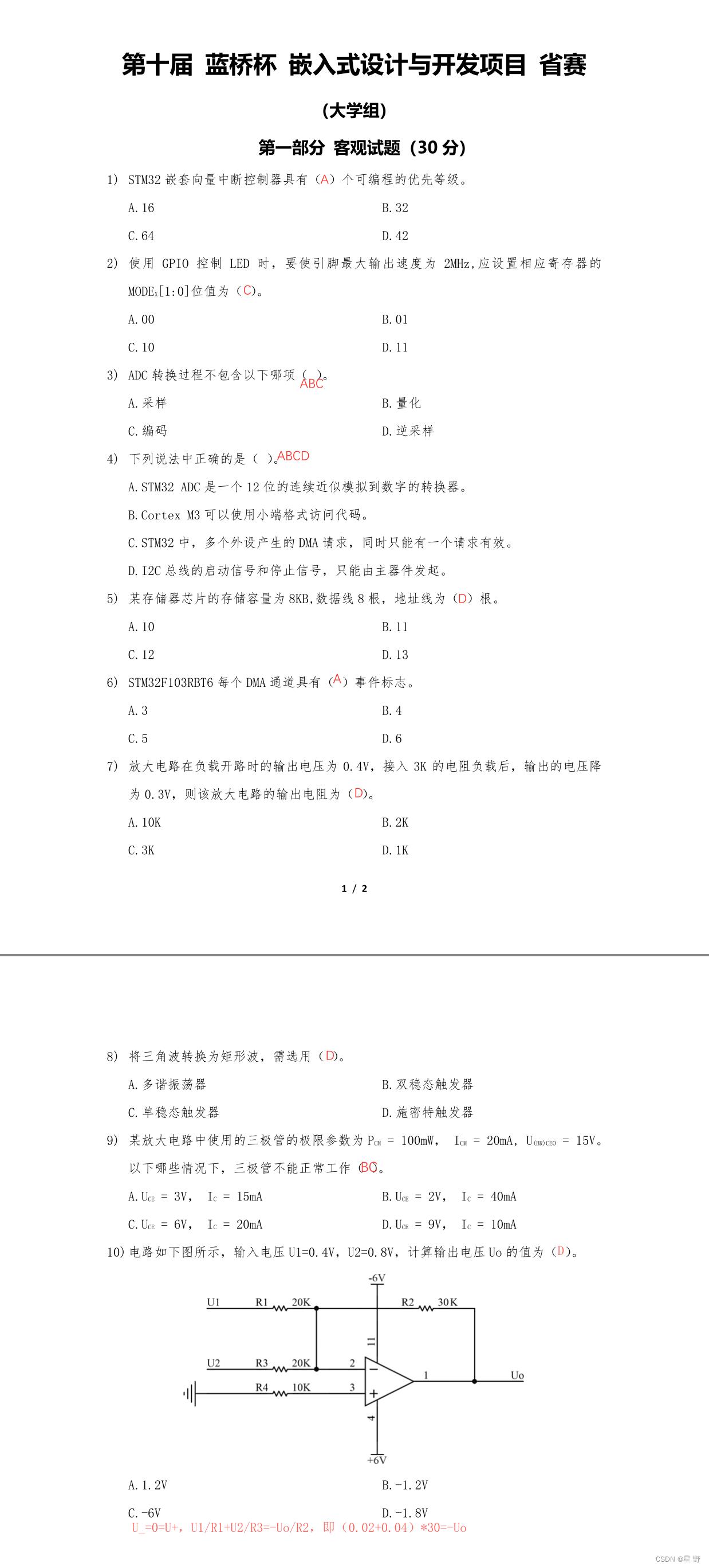
不理解的地方可以在评论区提问嗷,或者分享的百度云里解析。
程序设计题
题目解析

这次题目用到的模块是LCD,LED,按键和ADC,没什么好说的都是常用模块,但是还是又不一样的东西,那就是LCD显示时有‘高亮’提醒 。
‘高亮’显示也比较容易实现。
LCD_SetBackColor(Green),这个函数是LCD库提供的设置背景颜色。只要使用了一次,那后面的背景色就默认都是选中的颜色,所以我们就在需要高亮显示的那一行前使用这个函数修改背景色,显示完后再把背景改回原来的颜色。
例如,题目中原来的背景色是白色,高亮显示是绿色。
if(0 == choice)
	LCD_SetBackColor(Green);
sprintf(text,"   Max Volt: %.1fV  ",Max);
LCD_SHOW(2,text);
LCD_SetBackColor(White);
说完了,那还是从CubeMX的配置开始吧。说明一下使用的新版开发板G431。
CubeMX配置
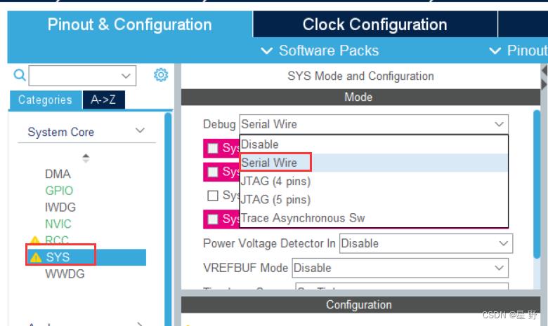
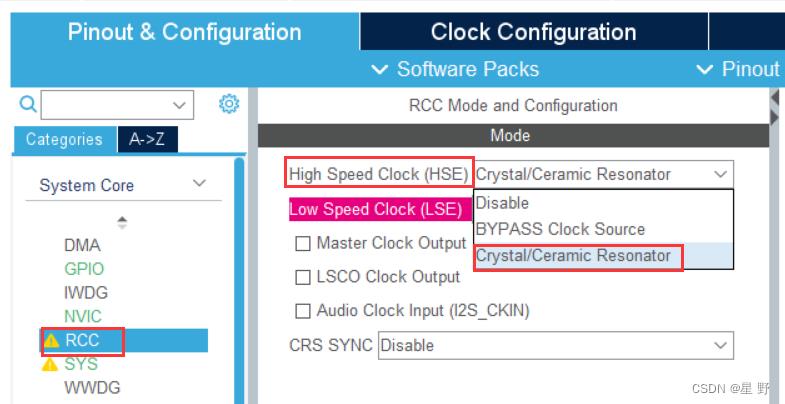
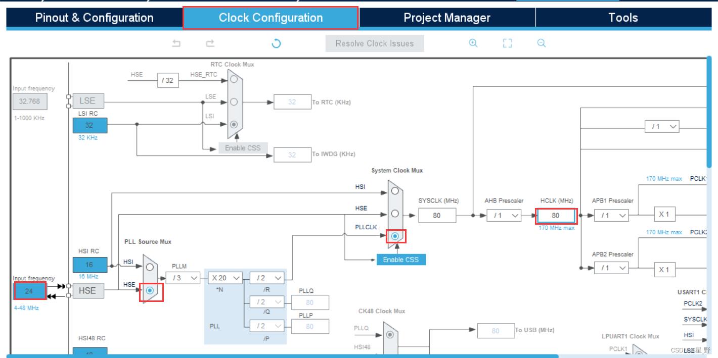
时钟配置完了,需要按下回车(Enter)来保存。
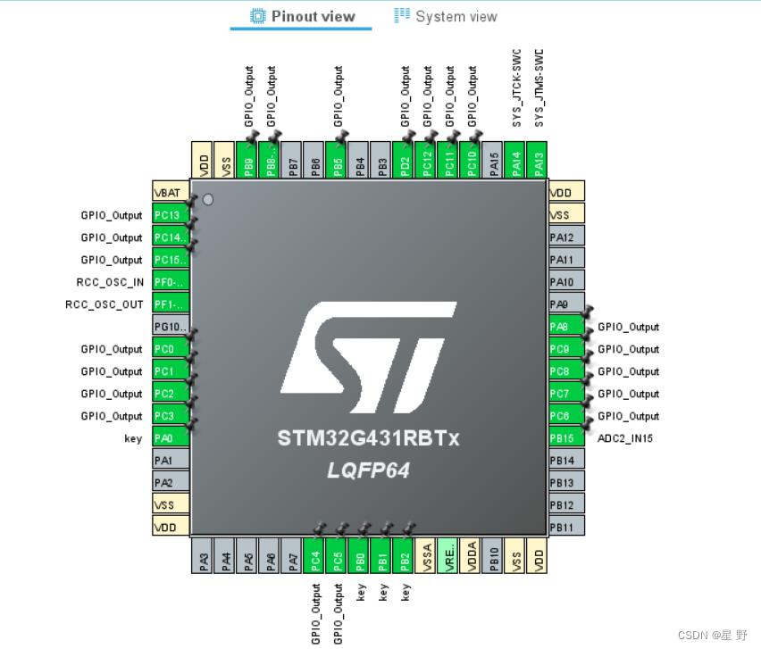
根据原理图配置GPIO引脚,其中lcd和led的引脚都设置为output,按键设置为input,PB15设置为ADC2的15通道,需要把PD2也设置为output用来作为led的锁存器。
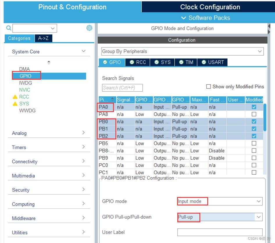
在GPIO中选中按键的引脚,设置为上拉输入模式。
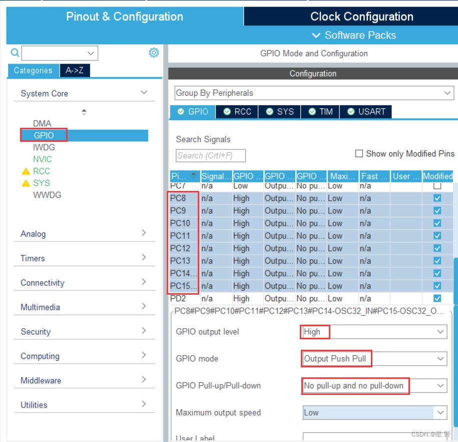
在GPIO中,选中led的引脚,设置为初始状态为高电平,推挽输出模式,既不上拉也不下拉。其他引脚使用默认设置就是行。
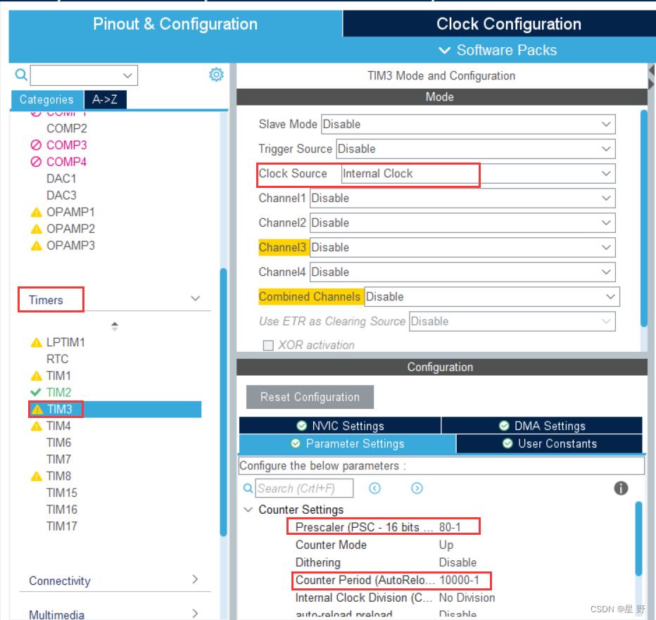
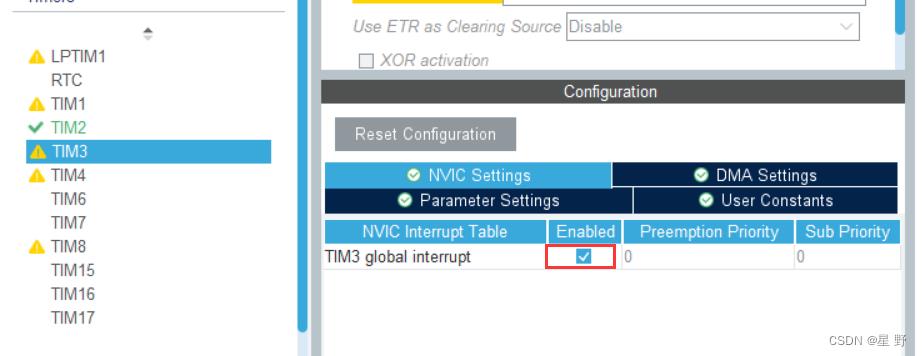
设置定时器3每10ms中断一次。
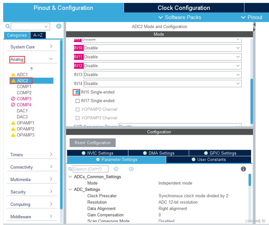
勾选ADC2的第15通道,其他设置默认就行。
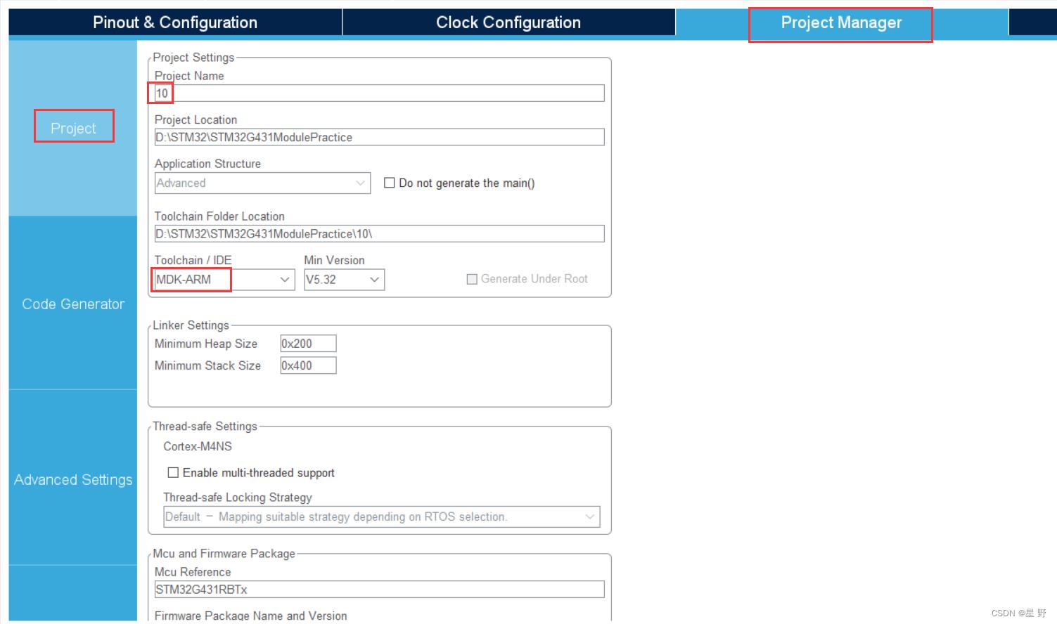 设置项目名字和保存路径(建议不要有中文),以及IDE的版本。
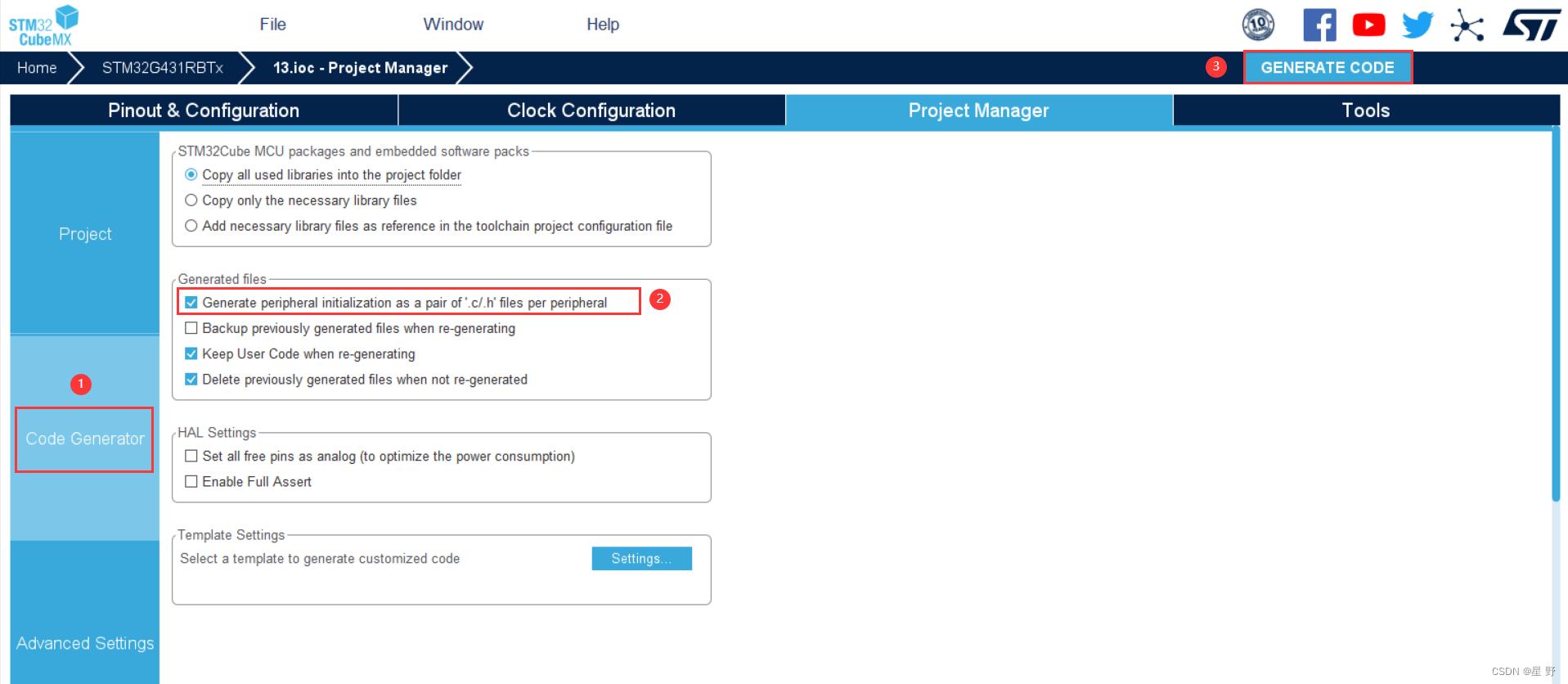
勾选这个主要是让.c和.h文件单独分开,之后就可以生成代码了,CubeMX配置就完成了,如果之后想要添加新的模块或者修改配置好了模块的值,可以直接在文件中打开CubeMX的工程进行修改,改完后再点击GENERATE CODE就行了。
代码演示
main.c
/* USER CODE BEGIN Header */
/**
  ******************************************************************************
  * @file           : main.c
  * @brief          : Main program body
  ******************************************************************************
  * @attention
  *
  * Copyright (c) 2023 STMicroelectronics.
  * All rights reserved.
  *
  * This software is licensed under terms that can be found in the LICENSE file
  * in the root directory of this software component.
  * If no LICENSE file comes with this software, it is provided AS-IS.
  *
  ******************************************************************************
  */
/* USER CODE END Header */
/* Includes ------------------------------------------------------------------*/
#include "main.h"
#include "adc.h"
#include "tim.h"
#include "gpio.h"

/* Private includes ----------------------------------------------------------*/
/* USER CODE BEGIN Includes */
#include "lcd.h"
#include "sys.h"
#include "show.h"
#include "timer.h"
/* USER CODE END Includes */

/* Private typedef -----------------------------------------------------------*/
/* USER CODE BEGIN PTD */

/* USER CODE END PTD */

/* Private define ------------------------------------------------------------*/
/* USER CODE BEGIN PD */
/* USER CODE END PD */

/* Private macro -------------------------------------------------------------*/
/* USER CODE BEGIN PM */

/* USER CODE END PM */

/* Private variables ---------------------------------------------------------*/

/* USER CODE BEGIN PV */
extern uint8_t btn;  //按键值

float Volt = 0.0f,Max = 2.4f,Min = 1.2f;
uint8_t Up = 1,Low = 2;  //Up是电压超过最大值的LED灯,Low是电压低于最小值的LED灯,不能相等
char Status[3][7] = "Upper","Lower","Normal";
uint8_t arrow = 0;   //指向当前状态,0是Upper,1是Lower,2是Normal
bool jm = 0;     //界面:0是数据显示界面,1是参数配置界面
uint8_t choice = 0;  //高亮显示,选择参数项
/* USER CODE END PV */

/* Private function prototypes -----------------------------------------------*/
void SystemClock_Config(void);
/* USER CODE BEGIN PFP */

/* USER CODE END PFP */

/* Private user code ---------------------------------------------------------*/
/* USER CODE BEGIN 0 */

/* USER CODE END 0 */

/**
  * @brief  The application entry point.
  * @retval int
  */
int main(void)

  /* USER CODE BEGIN 1 */

  /* USER CODE END 1 */

  /* MCU Configuration--------------------------------------------------------*/

  /* Reset of all peripherals, Initializes the Flash interface and the Systick. */
  HAL_Init();

  /* USER CODE BEGIN Init */

  /* USER CODE END Init */

  /* Configure the system clock */
  SystemClock_Config();

  /* USER CODE BEGIN SysInit */

  /* USER CODE END SysInit */

  /* Initialize all configured peripherals */
  MX_GPIO_Init();
  MX_ADC2_Init();
  MX_TIM3_Init();
  /* USER CODE BEGIN 2 */
  LCD_Init();
  LCD_Clear(White);
  LCD_SetBackColor(White);
  LCD_SetTextColor(Blue);

  HAL_TIM_Base_Start_IT(&htim3);
  /* USER CODE END 2 */

  /* Infinite loop */
  /* USER CODE BEGIN WHILE */
  while (1)

    /* USER CODE END WHILE */

    /* USER CODE BEGIN 3 */
	  Volt = GetADC(&hadc2);
	  switch(btn)

		  case 1:

			  jm ^= 1;
			  LCD_Clear(White);
			  btn = 0;

		  break;

		  case 2:

			  if(1 == jm)

				  choice ++;
				  if(4 == choice)
					  choice = 0;

			  btn = 0;

		  break;

		  case 3:

			  if(1 == jm)
				  ADD(choice);
			  if(Up == Low)  //如果Up的LED灯和Low的LED灯相等,被选择参数项就加一
				  ADD(choice);
			  btn = 0;

		  break;

		  case 4:

			  if(1 == jm)
				  SUB(choice);
			  if(Up == Low)  //如果Up的LED灯和Low的LED灯相等,被选择参数项就减一
				  SUB(choice);
			  btn = 0;

		  break;

	  Infer();
	  LED_SHOW();

	  if(0 == jm)
		  Data();
	  else
		  Setting();

  /* USER CODE END 3 */


/**
  * @brief System Clock Configuration
  * @retval None
  */
void SystemClock_Config(void)

  RCC_OscInitTypeDef RCC_OscInitStruct = 0;
  RCC_ClkInitTypeDef RCC_ClkInitStruct = 0;

  /** Configure the main internal regulator output voltage
  */
  HAL_PWREx_ControlVoltageScaling(PWR_REGULATOR_VOLTAGE_SCALE1);
  /** Initializes the RCC Oscillators according to the specified parameters
  * in the RCC_OscInitTypeDef structure.
  */
  RCC_OscInitStruct.OscillatorType = RCC_OSCILLATORTYPE_HSE;
  RCC_OscInitStruct.HSEState = RCC_HSE_ON;
  RCC_OscInitStruct.PLL.PLLState = RCC_PLL_ON;
  RCC_OscInitStruct.PLL.PLLSource = RCC_PLLSOURCE_HSE;
  RCC_OscInitStruct.PLL.PLLM = RCC_PLLM_DIV3;
  RCC_OscInitStruct.PLL.PLLN = 20;
  RCC_OscInitStruct.PLL.PLLP = RCC_PLLP_DIV2;
  RCC_OscInitStruct.PLL.PLLQ = RCC_PLLQ_DIV2;
  RCC_OscInitStruct.PLL.PLLR = RCC_PLLR_DIV2;
  if (HAL_RCC_OscConfig(&RCC_OscInitStruct) != HAL_OK)

    Error_Handler();

  /** Initializes the CPU, AHB and APB buses clocks
  */
  RCC_ClkInitStruct.ClockType = RCC_CLOCKTYPE_HCLK|RCC_CLOCKTYPE_SYSCLK
                              |RCC_CLOCKTYPE_PCLK1|RCC_CLOCKTYPE_PCLK2;
  RCC_ClkInitStruct.SYSCLKSource = RCC_SYSCLKSOURCE_PLLCLK;
  RCC_ClkInitStruct.AHBCLKDivider = RCC_SYSCLK_DIV1;
  RCC_ClkInitStruct.APB1CLKDivider = RCC_HCLK_DIV1;
  RCC_ClkInitStruct.APB2CLKDivider = RCC_HCLK_DIV1;

  if (HAL_RCC_ClockConfig(&RCC_ClkInitStruct, FLASH_LATENCY_2) != HAL_OK)

    Error_Handler();


/* USER CODE BEGIN 4 */

/* USER CODE END 4 */

/**
  * @brief  This function is executed in case of error occurrence.
  * @retval None
  */
void Error_Handler(void)

  /* USER CODE BEGIN Error_Handler_Debug */
  /* User can add his own implementation to report the HAL error return state */
  __disable_irq();
  while (1)


  /* USER CODE END Error_Handler_Debug */


#ifdef  USE_FULL_ASSERT
/**
  * @brief  Reports the name of the source file and the source line number
  *         where the assert_param error has occurred.
  * @param  file: pointer to the source file name
  * @param  line: assert_param error line source number
  * @retval None
  */
void assert_failed(uint8_t *file, uint32_t line)

  /* USER CODE BEGIN 6 */
  /* User can add his own implementation to report the file name and line number,
     ex: printf("Wrong parameters value: file %s on line %d\\r\\n", file, line) */
  /* USER CODE END 6 */

#endif /* USE_FULL_ASSERT */
main.h
/* USER CODE BEGIN Header */
/**
  ******************************************************************************
  * @file           : main.h
  * @brief          : Header for main.c file.
  *                   This file contains the common defines of the application.
  ******************************************************************************
  * @attention
  *
  * Copyright (c) 2023 STMicroelectronics.
  * All rights reserved.
  *
  * This software is licensed under terms that can be found in the LICENSE file
  * in the root directory of this software component.
  * If no LICENSE file comes with this software, it is provided AS-IS.
  *
  ******************************************************************************
  */
/* USER CODE END Header */

/* Define to prevent recursive inclusion -------------------------------------*/
#ifndef __MAIN_H
#define __MAIN_H

#ifdef __cplusplus
extern "C"
#endif

/* Includes ------------------------------------------------------------------*/
#include "stm32g4xx_hal.h"

/* Private includes ----------------------------------------------------------*/
/* USER CODE BEGIN Includes */
#include <stdio.h>
#include <stdbool.h>
#include <string.h>
/* USER CODE END Includes */

/* Exported types ------------------------------------------------------------*/
/* USER CODE BEGIN ET */

/* USER CODE END ET */

/* Exported constants --------------------------------------------------------*/
/* USER CODE BEGIN EC */

/* USER CODE END EC */

/* Exported macro ------------------------------------------------------------*/
/* USER CODE BEGIN EM */

/* USER CODE END EM */

/* Exported functions prototypes ---------------------------------------------*/
void Error_Handler(void);

/* USER CODE BEGIN EFP */

/* USER CODE END EFP */

/* Private defines -----------------------------------------------------------*/
#define key_Pin GPIO_PIN_0
#define key_GPIO_Port GPIOA
#define keyB0_Pin GPIO_PIN_0
#define keyB0_GPIO_Port GPIOB
#define keyB1_Pin GPIO_PIN_1
#define keyB1_GPIO_Port GPIOB
#define keyB2_Pin GPIO_PIN_2
#define keyB2_GPIO_Port GPIOB
/* USER CODE BEGIN Private defines */

/* USER CODE END Private defines */

#ifdef __cplusplus

#endif

#endif /* __MAIN_H */
main.h中添加了几个头文件和define。
sys.c
#include "sys.h"

Btn key[4] = 0;
uint8_t btn = 0;

extern float Max,Min;
extern uint8_t Up,Low,arrow;
extern bool Up_flag,Low_flag;  //Up的LED灯标志,Low的LED灯标志

void LED_SET(uint16_t Pin, GPIO_PinState PinState)

	HAL_GPIO_WritePin(GPIOC,GPIO_PIN_All,GPIO_PIN_SET);
	HAL_GPIO_WritePin(GPIOC,Pin,PinState);
	HAL_GPIO_WritePin(GPIOD,GPIO_PIN_2,GPIO_PIN_SET);
	HAL_GPIO_WritePin(GPIOD,GPIO_PIN_2,GPIO_PIN_RESET);


void LED_SHOW(void)

	if(1 == Up_flag)
		LED_SET(GPIO_PIN_8<<(Up-1),GPIO_PIN_RESET);
	else if(1 == Low_flag)
		LED_SET(GPIO_PIN_8<<(Low-1),GPIO_PIN_RESET);
	else
		LED_SET(GPIO_PIN_All,GPIO_PIN_SET);


void KEY_Scan(void)

	uint8_t i = 0;

	key[0].press = HAL_GPIO_ReadPin(GPIOB,GPIO_PIN_0);
	key[1].press = HAL_GPIO_ReadPin(GPIOB,GPIO_PIN_1);
	key[2].press = HAL_GPIO_ReadPin(GPIOB,GPIO_PIN_2);
	key[3].press = HAL_GPIO_ReadPin(GPIOA,GPIO_PIN_0);

	for(i=0;i<4;i++)

		switch(key[i].state)

			case 0:
				if(0 == key[i].press)
					key[i].state = 1;
			break;

			case 1:

				if(0 == key[i].press)

					key[i].state = 2;
					btn = i+1;

				else

					key[i].state = 0;


			break;

			case 2:
				if(1 == key[i].press)
					key[i].state = 0;
			break;


void ADD(uint8_t choice)

	switch(choice)

		case 0:

			Max += 0.3f;
			if(Max>3.3f)
				Max = 0.0f;

		break;

		case 1:

			Min += 0.3f;
			if(Min>3.3f)
				Min = 0.0f;

		break;

		case 2:

			Up++;
			if(9 == Up)
				Up = 1;

		break;

		case 3:

			Low++;
			if(9 == Low)
				Low = 1;

		break;


void SUB(uint8_t choice)

	switch(choice)

		case 0:

			Max -= 0.3f;
			if(Max<0.0f)
				Max = 3.3f;

		break;

		case 1:

			Min -= 0.3f;
			if(Min<0.0f)
				Min = 3.3f;

		break;

		case 2:

			Up--;
			if(0 == Up)
				Up = 8;

		break;

		case 3:

			Low--;
			if(0 == Low)
				Low = 8;

		break;
sys.h
#ifndef __SYS_H
#define __SYS_H

#include "main.h"

typedef struct
	bool press;
	uint8_t state;
Btn;

void LED_SET(uint16_t Pin, GPIO_PinState PinState);
void LED_SHOW(void);
void KEY_Scan(void);
void ADD(uint8_t choice);
void SUB(uint8_t choice);

#endif
show.c
#include "show.h"
char text[21] = 0;

extern float Volt,Max,Min;
extern uint8_t Up,Low;
extern char Status[][7];
extern uint8_t arrow;
extern uint8_t choice;

void LCD_SHOW(u8 line,char *text)

	LCD_DisplayStringLine(line*24,(u8 *)text);


void Data(void)

	sprintf(text,"        Main        ");
	LCD_SHOW(1,text);

	sprintf(text,"   Volt: %.2fV      ",Volt);
	LCD_SHOW(4,text);

	sprintf(text,"   Status: %s     ",Status[arrow]);
	LCD_SHOW(5,text);


void Setting(void)

	sprintf(text,"       Setting      ");
	LCD_SHOW(1,text);

	if(0 == choice)
		LCD_SetBackColor(Green);
	else
		LCD_SetBackColor(White);
	sprintf(text,"   Max Volt: %.1fV  ",Max);
	LCD_SHOW(2,text);

	if(1 == choice)
		LCD_SetBackColor(Green);
	else
		LCD_SetBackColor(White);
	sprintf(text,"   Min Volt: %.1fV  ",Min);
	LCD_SHOW(3,text);

	if(2 == choice)
		LCD_SetBackColor(Green);
	else
		LCD_SetBackColor(White);
	sprintf(text,"   Upper: LD%d      ",Up);
	LCD_SHOW(4,text);

	if(3 == choice)
		LCD_SetBackColor(Green);
	else
		LCD_SetBackColor(White);
	sprintf(text,"   Lower: LD%d      ",Low);
	LCD_SHOW(5,text);

	LCD_SetBackColor(White);


float GetADC(ADC_HandleTypeDef *pin)   //获取电压值

	uint16_t adc;
	HAL_ADC_Start(pin);
	adc = HAL_ADC_GetValue(pin);
	return adc*3.3/4096;


void Infer(void)   //判断电压的状态

	if(Volt>Max)
		arrow = 0;
	else if(Volt<Min)
		arrow = 1;
	else
		arrow = 2;
show.h
#ifndef __SHOW_H
#define __SHOW_H

#include "main.h"
#include "lcd.h"
#include "adc.h"
#include "sys.h"

void LCD_SHOW(u8 line,char *text);
void Data(void);
void Setting(void);
float GetADC(ADC_HandleTypeDef *pin);
void Infer(void);

#endif
timer.c
#include "timer.h"

uint8_t Up_Cnt = 0;
uint8_t Low_Cnt = 0;
bool Up_flag = 0,Low_flag = 0;  //LED闪烁的标志位

extern uint8_t Up,Low,arrow;

void HAL_TIM_PeriodElapsedCallback(TIM_HandleTypeDef *htim)

	if(TIM3 == htim->Instance)

		KEY_Scan();
		if(0 == arrow)

			if(20 == ++Up_Cnt)

				Up_Cnt = 0;
				Up_flag ^= 1;


		else

			Up_Cnt = 0;
			Up_flag = 0;


		if(1 == arrow)

			if(20 == ++Low_Cnt)

				Low_Cnt = 0;
				Low_flag ^= 1;


		else

			Low_Cnt = 0;
			Low_flag = 0;


		if(2 == arrow)
			LED_SET(GPIO_PIN_All,GPIO_PIN_SET);
timer.h
#ifndef __TIMER_H
#define __TIMER_H

#include "main.h"
#include "sys.h"

#endif
以上就是我修改过的文件和新添加的文件。还有lcd模块,不过不需要我们自己写,官方有提供,直接复制过来就行,注意有三个文件,别只复制lcd.c和lcd.h。
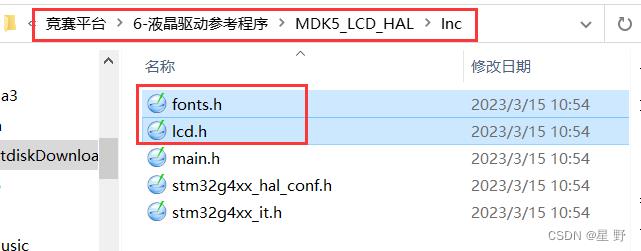
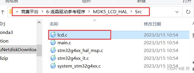
第十届的程序设计题是不难,只要逻辑正确就比较容易。 好了,以上就是蓝桥杯嵌入式第十届省赛的题目解析了,如果有什么问题和建议都欢迎在评论区提出来喔。
第十届蓝桥杯嵌入式国赛(STM32G4及HAL库)
前言
本程序基于STM32G431RB开发,使用工具为STM32CubeMX + Keil MDK 5 + HAL库。
题目说明


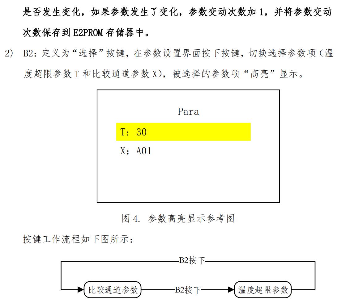

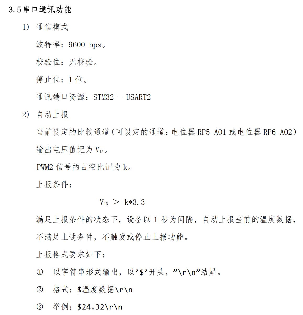


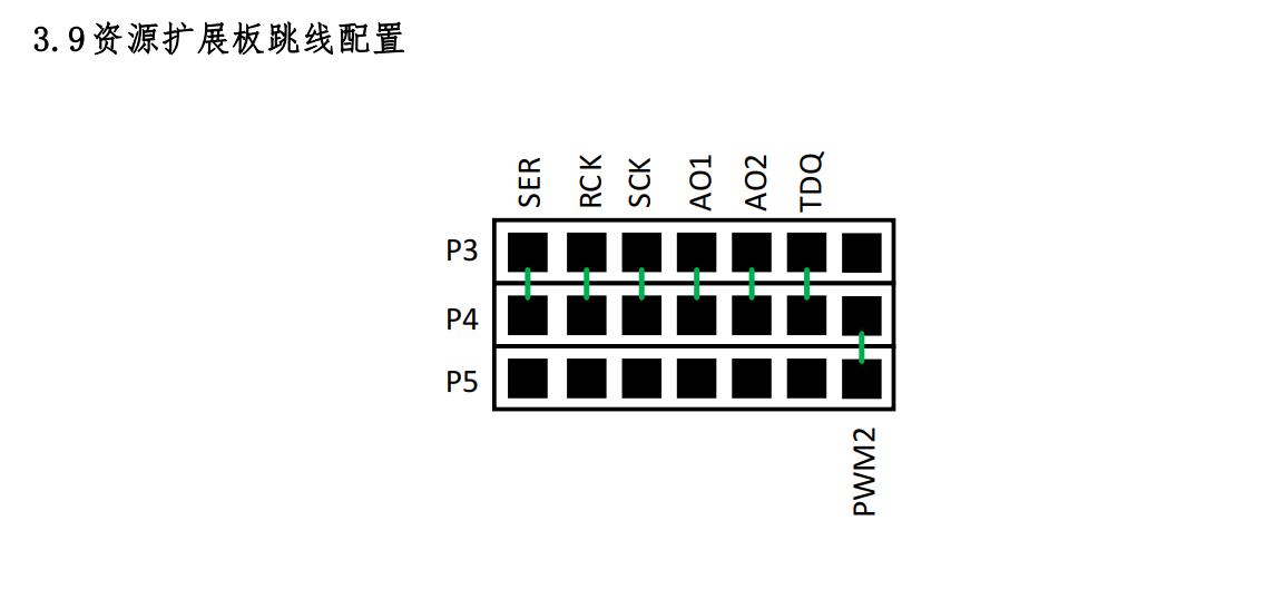
实现程序
为了方便提交,或者说不容易遗漏,本工程将绝大部分实现代码写在main.c文件中.
/* USER CODE BEGIN Header */
/**
******************************************************************************
* @file : main.c
* @brief : Main program body
******************************************************************************
* @attention
*
* <h2><center>© Copyright (c) 2021 STMicroelectronics.
* All rights reserved.</center></h2>
*
* This software component is licensed by ST under BSD 3-Clause license,
* the "License"; You may not use this file except in compliance with the
* License. You may obtain a copy of the License at:
* opensource.org/licenses/BSD-3-Clause
*
******************************************************************************
*/
/* USER CODE END Header */
/* Includes ------------------------------------------------------------------*/
#include "main.h"
/* Private includes ----------------------------------------------------------*/
/* USER CODE BEGIN Includes */
#include "stdio.h"
#include "string.h"
#include "ds18b20.h"
#include "i2c - hal.h"
/* USER CODE END Includes */
/* Private typedef -----------------------------------------------------------*/
/* USER CODE BEGIN PTD */
/* USER CODE END PTD */
/* Private define ------------------------------------------------------------*/
/* USER CODE BEGIN PD */
#define RCLK_PIN GPIO_PIN_2
#define SER_PIN GPIO_PIN_1
#define SCK_PIN GPIO_PIN_3
#define RCLK_H HAL_GPIO_WritePin(GPIOA, RCLK_PIN, GPIO_PIN_SET)
#define RCLK_L HAL_GPIO_WritePin(GPIOA, RCLK_PIN, GPIO_PIN_RESET)
#define SER_H HAL_GPIO_WritePin(GPIOA, SER_PIN, GPIO_PIN_SET)
#define SER_L HAL_GPIO_WritePin(GPIOA, SER_PIN, GPIO_PIN_RESET)
#define SCK_H HAL_GPIO_WritePin(GPIOA, SCK_PIN, GPIO_PIN_SET)
#define SCK_L HAL_GPIO_WritePin(GPIOA, SCK_PIN, GPIO_PIN_RESET)
/* USER CODE END PD */
/* Private macro -------------------------------------------------------------*/
/* USER CODE BEGIN PM */
/* USER CODE END PM */
/* Private variables ---------------------------------------------------------*/
ADC_HandleTypeDef hadc2;
TIM_HandleTypeDef htim3;
TIM_HandleTypeDef htim4;
UART_HandleTypeDef huart1;
/* USER CODE BEGIN PV */
char Text_buff[30]; //显示用
double AO1_Val = 0; //AO1电压值
double AO2_Val = 0;
uint8_t PWM2_zkb = 0;
double Temp_Val = 0;
uint16_t G_num = 0;
uint8_t Key1_Flag = 0;
uint8_t Key2_Flag = 0;
uint8_t Key3_Flag = 0;
uint8_t Key4_Flag = 0;
uint16_t IC3ReadValue1 = 0, IC3ReadValue2 = 0;
uint16_t CaptureNumber = 0;
uint32_t TIM3Freq = 0;
double TIM3Duty = 0;
uint32_t Capture_High = 0;
uint32_t Capture_Low = 0;
uint8_t Temp_Para = 30;
uint8_t X_Para = 0;
uint32_t Time = 0;
uint8_t mode = 0;
uc8 Seg7[17] = 0x3f, 0x06, 0x5b, 0x4f, 0x66, 0x6d, 0x7d, 0x07, 0x7f,
0x6f, 0x77, 0x7c, 0x39, 0x5e, 0x79, 0x71, 0x00;
uint8_t SEG_Flag = 0;
uint16_t ch = 0;
char rxbuff[30];
char RxBuff[30];
uint8_t Print_Flag = 0;
uint8_t N_Flag = 0;
uint8_t LED_8_Flag = 0;
/* USER CODE END PV */
/* Private function prototypes -----------------------------------------------*/
void SystemClock_Config(void);
static void MX_GPIO_Init(void);
static void MX_ADC2_Init(void);
static void MX_TIM3_Init(void);
static void MX_TIM4_Init(void);
static void MX_USART1_UART_Init(void);
/* USER CODE BEGIN PFP */
/* USER CODE END PFP */
/* Private user code ---------------------------------------------------------*/
/* USER CODE BEGIN 0 */
//获取ADC
double GetADC(uint32_t ch)
ADC_ChannelConfTypeDef sConfig = 0;
sConfig.Channel = ch;
sConfig.Rank = ADC_REGULAR_RANK_1;
sConfig.SamplingTime = ADC_SAMPLETIME_247CYCLES_5;
sConfig.SingleDiff = ADC_SINGLE_ENDED;
sConfig.OffsetNumber = ADC_OFFSET_NONE;
sConfig.Offset = 0;
if (HAL_ADC_ConfigChannel(&hadc2, &sConfig) != HAL_OK)
Error_Handler();
HAL_ADC_Start(&hadc2);
HAL_ADC_PollForConversion(&hadc2,10);
uint16_t adc = HAL_ADC_GetValue(&hadc2);
return (adc*3.3/4096);
均值滤波
//u16 ADC_Average(u32 ch, u8 times)
//
// u32 temp_val = 0;
// u8 t;
// for(t = 0; t < times; t++)
// temp_val += GetADC(ch);
// HAL_Delay(5);
//
//
// return temp_val/times;
//
//
void HAL_TIM_IC_CaptureCallback(TIM_HandleTypeDef *htim)
if(htim -> Instance == TIM3)
if(htim->Channel == HAL_TIM_ACTIVE_CHANNEL_2)
if(CaptureNumber == 0)
IC3ReadValue1 = TIM3->CCR2;
CaptureNumber = 1;
__HAL_TIM_SET_CAPTUREPOLARITY(htim,TIM_CHANNEL_2,TIM_INPUTCHANNELPOLARITY_FALLING);
else if(CaptureNumber == 1)
IC3ReadValue2 = TIM3->CCR2;
CaptureNumber = 2;
__HAL_TIM_SET_CAPTUREPOLARITY(htim,TIM_CHANNEL_2,TIM_INPUTCHANNELPOLARITY_RISING);
if (IC3ReadValue2 > IC3ReadValue1)
Capture_High = (IC3ReadValue2 - IC3ReadValue1);
else
Capture_High = ((0xFFFF - IC3ReadValue1) + IC3ReadValue2);
IC3ReadValue1 = IC3ReadValue2;
else if(CaptureNumber == 2)
IC3ReadValue2 = TIM3->CCR2;
CaptureNumber = 0;
if (IC3ReadValue2 > IC3ReadValue1)
Capture_Low = (IC3ReadValue2 - IC3ReadValue1);
else
Capture_Low = ((0xFFFF - IC3ReadValue1) + IC3ReadValue2);
TIM3Freq = (uint32_t) 1000000 / (Capture_Low + Capture_High);
TIM3Duty = Capture_High * 1.0 / (Capture_Low + Capture_High);
double GetTemp()
u16 read = (ds18b20_read() & 0x07FF);
return (read/16.);
//主界面
void MainDisplay()
//赋值
AO1_Val = GetADC(ADC_CHANNEL_17);
AO2_Val = GetADC(ADC_CHANNEL_13);
PWM2_zkb = TIM3Duty * 100 ;
Temp_Val = GetTemp();
//显示部分
LCD_DisplayStringLine(Line1,(uint8_t *)" Main ");
sprintf(Text_buff," AO1:%.2f V ",AO1_Val);
LCD_DisplayStringLine(Line2,(uint8_t *)Text_buff);
sprintf(Text_buff," AO2:%.2f V ",AO2_Val);
LCD_DisplayStringLine(Line3,(uint8_t *)Text_buff);
sprintf(Text_buff," PWM2:%d %% ",PWM2_zkb);
LCD_DisplayStringLine(Line4,(uint8_t *)Text_buff);
sprintf(Text_buff," Temp:%.2f 'C ",Temp_Val);
LCD_DisplayStringLine(Line5,(uint8_t *)Text_buff);
sprintf(Text_buff," N:%d ",G_num);
LCD_DisplayStringLine(Line7,(uint8_t *)Text_buff);
//参数配置界面
void ParaDisply()
LCD_DisplayStringLine(Line1,(uint8_t *)" Para ");
sprintf(Text_buff," T:%d ",Temp_Para);
if(Key2_Flag == 1)
LCD_SetBackColor(Yellow);
LCD_DisplayStringLine(Line2,(uint8_t *)Text_buff);
LCD_SetBackColor(Blue);
else
LCD_DisplayStringLine(Line2,(uint8_t *)Text_buff);
sprintf(Text_buff," X:AO%d ",X_Para+1);
if(Key2_Flag == 2)
LCD_SetBackColor(Yellow);
LCD_DisplayStringLine(Line3,(uint8_t *)Text_buff);
LCD_SetBackColor(Blue);
else
LCD_DisplayStringLine(Line3,(uint8_t *)Text_buff);
LCD_DisplayStringLine(Line4,(uint8_t *)" ");
LCD_DisplayStringLine(Line5,(uint8_t *)" ");
LCD_DisplayStringLine(Line7,(uint8_t *)" ");
//定时1ms
void HAL_TIM_PeriodElapsedCallback(TIM_HandleTypeDef *htim)
static uint16_t TIM4_Cnt1 = 0;
static uint16_t SEG_Cnt1 = 0;
static uint16_t Print_Cnt1 = 0;
static uint16_t LED_Cnt1 = 0;
if(htim->Instance == TIM4)
TIM4_Cnt1++;
if(TIM4_Cnt1 >= 100)
TIM4_Cnt1 = 0;
SEG_Cnt1++;
Print_Cnt1++;
LED_Cnt1++;
if(LED_Cnt1 >= 8)
LED_Cnt1 = 0;
LED_8_Flag = !LED_8_Flag;
if(Print_Cnt1 >= 10)
Print_Cnt1 = 0;
Print_Flag = 1;
if(SEG_Cnt1 >= 20)
SEG_Cnt1 = 0;
SEG_Flag = !SEG_Flag;
Time++;
void KeyScan()
static u8 key_up=1; //按键松开标志
static u8 key_ups=1;
if(key_ups && (HAL_GPIO_ReadPin(GPIOA, GPIO_PIN_0) == RESET
|| HAL_GPIO_ReadPin(GPIOB, GPIO_PIN_2) == RESET ))
Time = 0;
key_ups = 0;
N_Flag = 1;
else if(HAL_GPIO_ReadPin(GPIOA, GPIO_PIN_0) == SET
&& HAL_GPIO_ReadPin(GPIOB, GPIO_PIN_2) == SET)
key_ups = 1;
if(Time >= 8) mode = 1;
else mode = 0;
if(Time > 5000) Time = 0;
if(mode == 1) key_up = 1;
if(key_up && (HAL_GPIO_ReadPin(GPIOA, GPIO_PIN_0) == RESET
|| HAL_GPIO_ReadPin(GPIOB, GPIO_PIN_2) == RESET))
key_up = 0;
if(HAL_GPIO_ReadPin(GPIOB, GPIO_PIN_2) == RESET)
if(Key2_Flag == 1)
Temp_Para++;
if(Temp_Para > 40)
Temp_Para = 40;
if(Key2_Flag == 2)
X_Para = !X_Para;
if(HAL_GPIO_ReadPin(GPIOA, GPIO_PIN_0) == RESET)
if(Key2_Flag == 1)
Temp_Para--;
if(Temp_Para < 20)
Temp_Para = 20;
if(Key2_Flag == 2)
X_Para = !X_Para;
else if(HAL_GPIO_ReadPin(GPIOA, GPIO_PIN_0) == SET
&& HAL_GPIO_ReadPin(GPIOB, GPIO_PIN_2) == SET)
key_up = 1;
void SEG_Display(u8 Bit1, u8 Bit2, u8 Bit3)
u8 i = 0;
u8 code_tmp = 0;
RCLK_L;
code_tmp = Seg7[Bit3];
for(i = 0; i < 8; i++)
SCK_L;
if(code_tmp & 0x80)
SER_H;
else
SER_L;
code_tmp = code_tmp << 1;
SCK_L;
SCK_H;
code_tmp = Seg7[Bit2];
for(i = 0; i < 8; i++)
SCK_L;
if(code_tmp & 0x80)
SER_H;
else
SER_L;
code_tmp = code_tmp << 1;
SCK_L;
SCK_H;
code_tmp = Seg7[Bit1];
for(i = 0; i < 8; i++)
SCK_L;
if(code_tmp & 0x80)
SER_H;
else
SER_L;
code_tmp = code_tmp << 1;
SCK_L;
SCK_H;
RCLK_L;
RCLK_H;
void SEG()
if(SEG_Flag == 0)
u8 SEG_temp_1 = Temp_Para/10;
u8 SEG_temp_2 = Temp_Para%10;
SEG_Display(12, SEG_temp_1, SEG_temp_2);
else
SEG_Display(10, 0, X_Para+1);
void My_Printf()
if(X_Para == 0 && (AO1_Val > (TIM3Duty * 3.3)) )
HAL_GPIO_WritePin(GPIOC, GPIO_PIN_13 | GPIO_PIN_14 | GPIO_PIN_15
| GPIO_PIN_9 | GPIO_PIN_10 | GPIO_PIN_11 | GPIO_PIN_12, GPIO_PIN_SET);
HAL_GPIO_WritePin(GPIOC, GPIO_PIN_8, GPIO_PIN_RESET);
HAL_GPIO_WritePin(GPIOD, GPIO_PIN_2, GPIO_PIN_SET);
HAL_GPIO_WritePin(GPIOD, GPIO_PIN_2, GPIO_PIN_RESET);
if(Print_Flag == 1)
printf("$%.2f\\r\\n",Temp_Val);
Print_Flag = 0;
if(X_Para == 1 && (AO2_Val > (TIM3Duty * 3.3)))
HAL_GPIO_WritePin(GPIOC, GPIO_PIN_13 | GPIO_PIN_14 | GPIO_PIN_15
| GPIO_PIN_9 | GPIO_PIN_10 | GPIO_PIN_11 | GPIO_PIN_12, GPIO_PIN_SET);
HAL_GPIO_WritePin(GPIOC, GPIO_PIN_8, GPIO_PIN_RESET);
HAL_GPIO_WritePin(GPIOD, GPIO_PIN_2, GPIO_PIN_SET);
HAL_GPIO_WritePin(GPIOD, GPIO_PIN_2, GPIO_PIN_RESET);
if( Print_Flag == 1)以上是关于蓝桥杯嵌入式第十届初赛题目解析的主要内容,如果未能解决你的问题,请参考以下文章