Unity3D选中物体描边特效
Posted little_fat_sheep
tags:
篇首语:本文由小常识网(cha138.com)小编为大家整理,主要介绍了Unity3D选中物体描边特效相关的知识,希望对你有一定的参考价值。
1 前言
描边的难点在于如何检测和识别边缘,当前实现描边特效的方法主要有以下几种:
1)基于顶点膨胀的描边方法
在 SubShader 中开 2 个 Pass 渲染通道,第一个 Pass 通道渲染膨胀的顶点,即将顶点坐标沿着法线方向向外扩展,并使用纯色给扩展后的顶点着色,第二个 Pass 通道渲染原顶点,并覆盖第一个 Pass 通道渲染的内部。
该方案实现简单,算法效率高,但是对于拐角较大的两个面交界处,会出现描边断裂,并且描边的宽度会受到透视投影影响。
基于模板测试和顶点膨胀的描边方法 解决了描边断裂和描边宽度受透视影响问题。
2)基于法线的描边方法
对于物体的任意一顶点,判断视线向量(该点指向相机的向量)与该点法线向量的夹角(记为 θ)是否近似 90 度,如果近似 90 度,就将该点识别为边缘,并进行边缘着色。实际应用中,通常采用模糊描边着色法,而不是阈值法,即将 sin(θ) 作为该点渲染描边色的强度。
该方案属于内描边,实现简单,算法效率高,但是物体中间 θ 值近似 90 度的地方也会被描边。
3)基于深度纹理的描边方法
对渲染后的屏幕纹理进行二次渲染,根据像素点周围颜色的差异判断是否是物体边缘像素,如果是边缘,需要重新进行边缘着色。判断边缘的具体做法是:对该像素点周围的像素点进行卷积运算,得到该点的梯度(反映该点附件颜色突变的强度),根据梯度阈值判断该点是否是边缘。
该方案属于内描边,实现有一定难度,算法效率一般,算法依赖梯度阈值,并且受颜色、光照、阴影等影响较大如:地面的影子可能会被描边。
4)基于法线和深度纹理的描边方法
通过引入法线纹理,对方案 3) 进行优化。该方案不仅考虑了深度纹理图中任意点的梯度,还考虑了法线纹理图中该点的梯度,通过综合两种梯度和梯度阈值,确定该点是否需要边缘着色。
该方案属于内描边,效果较好,实现较难,算法依赖梯度阈值。
5)基于模板纹理模糊膨胀的描边方法
首先使用纯色对选中的物体进行渲染,得到模板纹理,接着对模板纹理进行模糊处理,使模板颜色往外扩,得到模糊纹理,再根据模板纹理和模糊纹理对所有物体重新渲染,渲染规则:如果该像素点在模板纹理内部,就渲染原色,如果在模板纹理外部,就根据模糊纹理的透明度判断渲染原色还是模糊纹理色。
该方案属于外描边,效果较好,实现较难,但算法不依赖阈值。
本文代码资源见→Unity3D选中物体描边特效。
2 基本原理
本文采用基于模板纹理模糊膨胀的描边方法,本节将通过图文详细介绍该算法的原理。
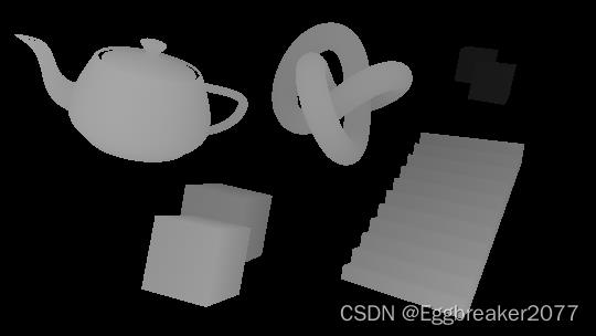
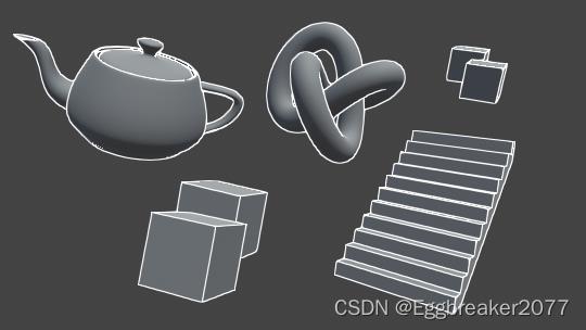
1)原图
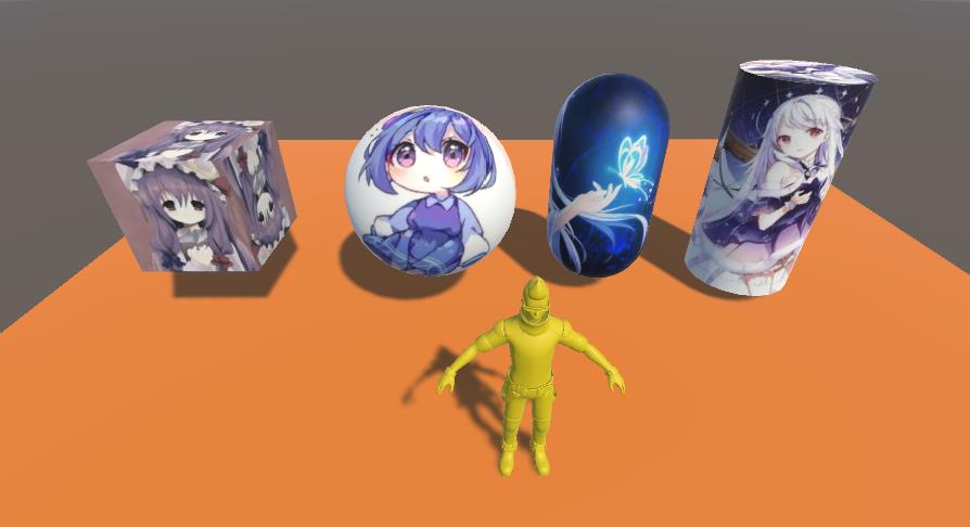
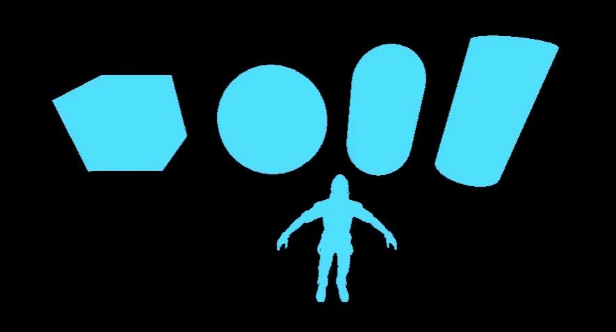
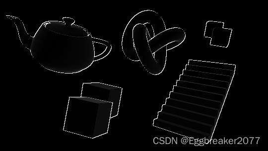
2)模板纹理
说明:清屏颜色为 (0, 0, 0, 0),后面会用到 。通过 Graphics.ExecuteCommandBuffer(commandBuffer) 对选中的物体进行渲染,得到模板纹理。
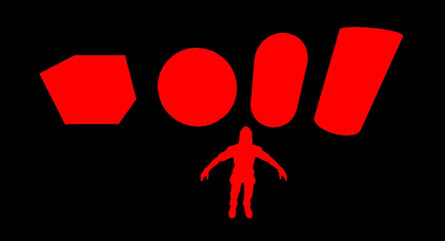
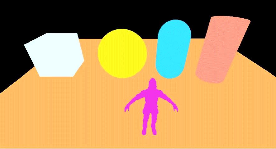
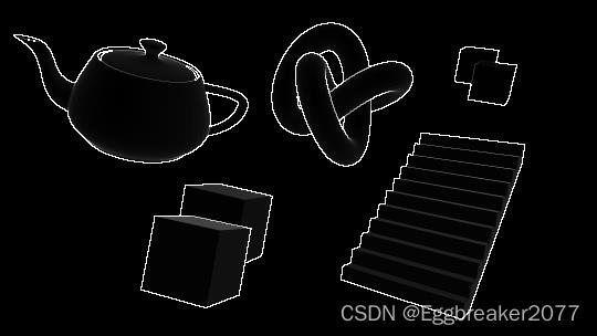
3)模糊纹理
说明:通过对模板纹理进行模糊处理, 使模板颜色向外扩展,得到模糊纹理,外扩的部分就是需要描边的部分。
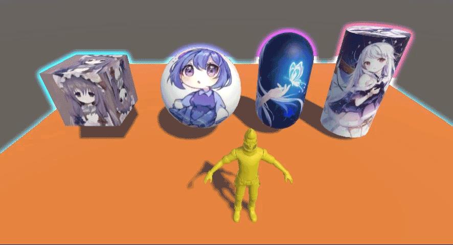
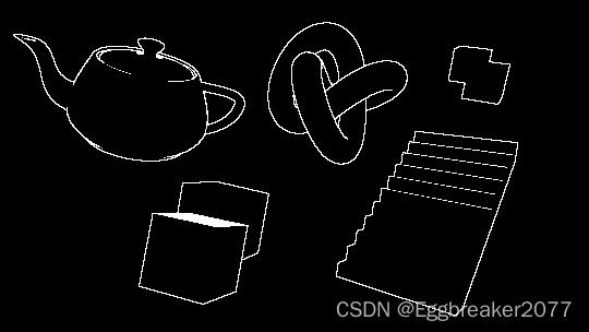
4)合成纹理
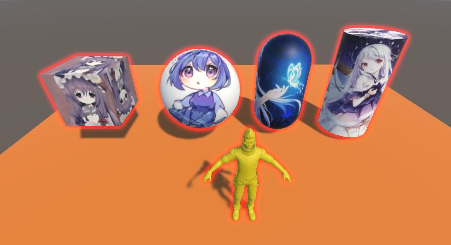
说明:根据模板纹理和模糊纹理对所有物体重新渲染,渲染规则:如果该像素点在模板纹理内部,就渲染原色,如果在模板纹理外部,就根据模糊纹理的透明度判断渲染原色还是模糊纹理色,如下:
// 由于模糊纹理的外部清屏颜色是(0, 0, 0, 0), blur.a=0, 因此模糊纹理的外部也会被渲染为原色
color.rgb = lerp(source.rgb, blur.rgb, blur.a); // lerp(a,b,x)=(1-x)*a+x*b
color.a = source.a;
5)描边颜色和宽度渐变
描边颜色由模板颜色决定,通过设置模板颜色随时间变化,实现描边颜色渐变,通过设置模板透明度随时间变化,实现描边在出现和消失,视觉上感觉描边在扩大和缩小。
fixed4 frag(v2f i) : SV_Target // 片段着色器

    float t1 = sin(_Time.z); // _Time = float4(t/20, t, t*2, t*3)
	float t2 = cos(_Time.z);
	// 描边颜色随时间变化, 描边透明度随时间变化, 视觉上感觉描边在膨胀和收缩
	return float4(t1 + 1, t2 + 1, 1 - t1, 1 - t2);
渐变模板图如下:
渐变描边效果如下:

6)缺陷
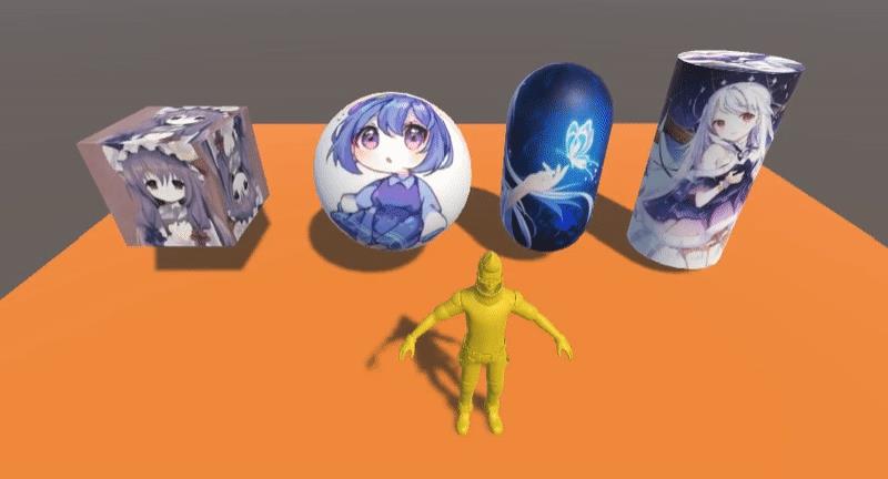
如果描边的物体存在重叠,由于所有物体共一个模板纹理,将存在描边消融现象。
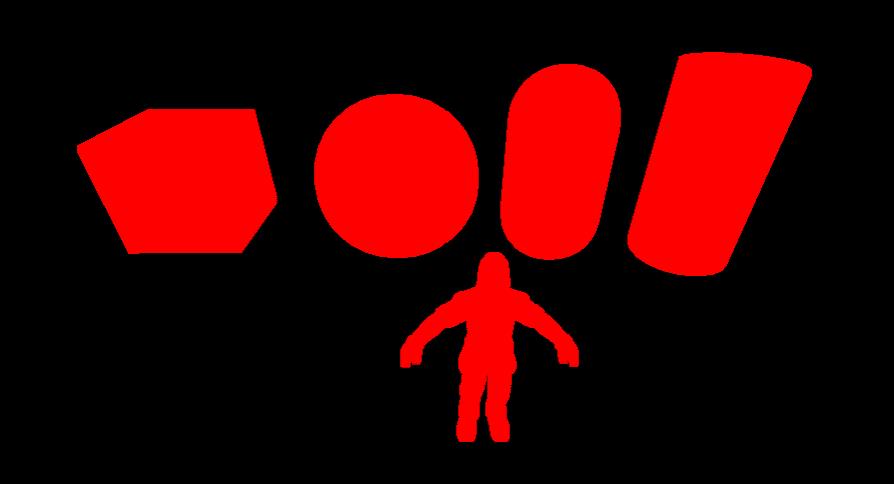
模板纹理如下:
描边消融如下:
可以看到,正方体、球体、胶囊体、圆柱体下方及人体都没有描边特效,因为它们在模板纹理的内部,被消融掉了。
3 代码实现
OutlineEffect.cs
using System;
using UnityEngine;
using UnityEngine.Rendering;

public class OutlineEffect : MonoBehaviour
    public static Action<CommandBuffer> renderEvent; // 渲染事件
    public float offsetScale = 2; // 模糊处理像素偏移
    public int iterate = 3; // 模糊处理迭代次数
    public float outlineStrength = 3; // 描边强度

    private Material blurMaterial; // 模糊材质
    private Material compositeMaterial; // 合成材质
    private CommandBuffer commandBuffer; // 用于渲染模板纹理
    private RenderTexture stencilTex; // 模板纹理
    private RenderTexture blurTex; // 模糊纹理

    private void Awake()
        blurMaterial = new Material(Shader.Find("Custom/Outline/Blur"));
        compositeMaterial = new Material(Shader.Find("Custom/Outline/Composite"));
        commandBuffer = new CommandBuffer();


    private void OnRenderImage(RenderTexture source, RenderTexture destination)
        if (renderEvent != null)
            RenderStencil(); // 渲染模板纹理
            RenderBlur(source.width, source.height); // 渲染模糊纹理
            RenderComposite(source, destination); // 渲染合成纹理
         else
            Graphics.Blit(source, destination); // 保持原图


    private void RenderStencil()  // 渲染模板纹理
        stencilTex = RenderTexture.GetTemporary(Screen.width, Screen.height, 0);
        commandBuffer.SetRenderTarget(stencilTex);
        commandBuffer.ClearRenderTarget(true, true, Color.clear); // 设置模板清屏颜色为(0,0,0,0)
        renderEvent.Invoke(commandBuffer);
        Graphics.ExecuteCommandBuffer(commandBuffer);


    private void RenderBlur(int width, int height)  // 对模板纹理进行模糊化
        blurTex = RenderTexture.GetTemporary(width, height, 0);
        RenderTexture temp = RenderTexture.GetTemporary(width, height, 0);
        blurMaterial.SetFloat("_OffsetScale", offsetScale);
        Graphics.Blit(stencilTex, blurTex, blurMaterial);
        for (int i = 0; i < iterate; i ++)
            Graphics.Blit(blurTex, temp, blurMaterial);
            Graphics.Blit(temp, blurTex, blurMaterial);

        RenderTexture.ReleaseTemporary(temp);


    private void RenderComposite(RenderTexture source, RenderTexture destination)  // 渲染合成纹理
        compositeMaterial.SetTexture("_MainTex", source);
        compositeMaterial.SetTexture("_StencilTex", stencilTex);
        compositeMaterial.SetTexture("_BlurTex", blurTex);
        compositeMaterial.SetFloat("_OutlineStrength", outlineStrength);
        Graphics.Blit(source, destination, compositeMaterial);
        RenderTexture.ReleaseTemporary(stencilTex);
        RenderTexture.ReleaseTemporary(blurTex);
        stencilTex = null;
        blurTex = null;
说明: OnRenderImage 方法是MonoBehaviour的生命周期方法,在所有的渲染完成后由 MonoBehavior 自动调用,该方法依赖相机组件,由于 OnRenderImage 在渲染后调用,因此被称为后处理操作,它是 Unity3D 特效的重要理论分支;Graphics.Blit(source, dest, material) 用于将 source 纹理按照 material 材质重新渲染到 dest;CommandBuffer 携带一系列的渲染命令,依赖相机,用来拓展渲染管线的渲染效果;OutlineEffect 脚本组件必须挂在相机上。
OutlineObject.cs
using UnityEngine;
using UnityEngine.Rendering;

public class OutlineObject : MonoBehaviour
    private Material stencilMaterial; // 模板材质

    private void Awake()
        stencilMaterial = new Material(Shader.Find("Custom/Outline/Stencil"));


    private void OnEnable()
        OutlineEffect.renderEvent += OnRenderEvent;
        // _StartTime用于控制每个选中的对象颜色渐变不同步
        stencilMaterial.SetFloat("_StartTime", Time.timeSinceLevelLoad * 2);


    private void OnDisable()
        OutlineEffect.renderEvent -= OnRenderEvent;


    private void OnRenderEvent(CommandBuffer commandBuffer)
        Renderer[] renderers = gameObject.GetComponentsInChildren<Renderer>();
        foreach (Renderer r in renderers)
            commandBuffer.DrawRenderer(r, stencilMaterial); // 将renderer和material提交到主camera的commandbuffer列表进行渲染
说明:被选中的物体将会添加 OutlineObject 脚本组件,用于渲染选中对象的模板纹理,每个选中对象独立持有 stencilMaterial,互不干扰,描边的渐变相位(由_StartTime控制)可以由选中对象独立控制,这样每个模板的颜色就可以独立控制,从而实现每个选中对象描边各异的效果。
SelectController.cs
using System.Collections.Generic;
using UnityEngine;

public class SelectController : MonoBehaviour
    private List<GameObject> targets; // 选中的游戏对象
    private List<GameObject> loseFocus; // 失焦的游戏对象
    private RaycastHit hit; // 碰撞信息

    private void Start()
        Camera.main.gameObject.AddComponent<OutlineEffect>();
        targets = new List<GameObject>();
        loseFocus = new List<GameObject>();
        hit = new RaycastHit();


    private void Update()
        if (Input.GetMouseButtonUp(0))
            GameObject hitObj = GetHitObj();
            if (hitObj == null)  // 未选中任何物体, 已描边的全部取消描边
                targets.ForEach(obj => loseFocus.Add(obj));
                targets.Clear();

            else if (Input.GetKey(KeyCode.LeftControl) || Input.GetKey(KeyCode.RightControl))
                if (targets.Contains(hitObj))  // Ctrl重复选中, 取消描边
                    loseFocus.Add(hitObj);
                    targets.Remove(hitObj);
                 else  // Ctrl追加描边
                    targets.Add(hitObj);

             else  // 单选描边
                targets.ForEach(obj => loseFocus.Add(obj));
                targets.Clear();
                targets.Add(hitObj);
                loseFocus.Remove(hitObj);

            DrawOutline();


    private void DrawOutline()  // 描边
        targets.ForEach(obj =>
            if (obj.GetComponent<OutlineObject>() == null)
                obj.AddComponent<OutlineObject>();
             else
                obj.GetComponent<OutlineObject>().enabled = true;

        );
        loseFocus.ForEach(obj =>
            if (obj.GetComponent<OutlineObject>() != null)
                obj.GetComponent<OutlineObject>().enabled = false;

        );
        loseFocus.Clear();


    private GameObject GetHitObj()  // 获取屏幕射线碰撞的物体
        Ray ray = Camera.main.ScreenPointToRay(Input.mousePosition);
        if (Physics.Raycast(ray, out hit))
            return hit.collider.gameObject;

        return null;
说明:通过单击物体,给选中的物体添加 OutlineObject 脚本组件,再由 OutlineEffect 控制描边。按住 Ctrl 键再单击物体会追加选中,如果重复选中,会取消描边。
StencilShader.shader
Shader "Custom/Outline/Stencil"

	Properties

		_StartTime ("startTime", Float) = 0 // _StartTime用于控制每个选中的对象颜色渐变不同步


	SubShader

		Pass

			CGPROGRAM // CG语言的开始
			// 编译指令 着色器名称 函数名称
			#pragma vertex vert // 顶点着色器, 每个顶点执行一次
			#pragma fragment frag // 片段着色器, 每个像素执行一次
			#pragma fragmentoption ARB_precision_hint_fastest // fragment使用最低精度, fp16, 提高性能和速度

			// 导入头文件
			#include "UnityCG.cginc"

			float _StartTime;

			struct appdata // 顶点函数输入结构体

				half4 vertex: POSITION; // 顶点坐标
			;

			struct v2f // 顶点函数输出结构体

				float4 pos : SV_POSITION;
			;

			v2f vert(appdata v) // 顶点着色器

				v2f o;
				o.pos = UnityObjectToClipPos(v.vertex);
				return o;


			fixed4 frag(v2f i) : SV_Target // 片段着色器

				float t1 = sin(_Time.z - _StartTime); // _Time = float4(t/20, t, t*2, t*3)
				float t2 = cos(_Time.z - _StartTime);
				// 描边颜色随时间变化, 描边透明度随时间变化, 视觉上感觉描边在膨胀和收缩
				return float4(t1 + 1, t2 + 1, 1 - t1, 1 - t2);


			ENDCG // CG语言的结束


	FallBack off
说明: StencilShader 用于渲染模板纹理,并且其颜色和透明度随时间变化,实现描边颜色渐变、宽度在膨胀和收缩效果。_StartTime 用于控制时间偏移,由物体被选中的时间决定,每个物体被选中的时间不一样,因此选中物体模板颜色各异,描边颜色也各异。
BlurShader.shader
Shader "Custom/Outline/Blur"

	Properties

		_MainTex ("stencil", 2D) = ""
		_OffsetScale ("offsetScale", Range (0.1, 3)) = 2 // 模糊采样偏移


	SubShader

		Pass

			ZTest Always
			Cull Off
			ZWrite Off
			Lighting Off
			Fog  Mode Off

			CGPROGRAM // CG语言的开始
			#pragma vertex vert // 顶点着色器, 每个顶点执行一次
			#pragma fragment frag // 片段着色器, 每个像素执行一次
			#pragma fragmentoption ARB_precision_hint_fastest // fragment使用最低精度, fp16, 提高性能和速度

			#include "UnityCG.cginc"

			sampler2D _MainTex;
			half _OffsetScale;
			half4 _MainTex_TexelSize; //_MainTex的像素尺寸大小, float4(1/width, 1/height, width, height)

			struct appdata // 顶点函数输入结构体

				half4 vertex: POSITION;
				half2 texcoord: TEXCOORD0;
			;

			struct v2f // 顶点函数输出结构体

				float4 pos : POSITION;
				half2 uv[4] : TEXCOORD0;
			;

			v2f vert (appdata v) // 顶点着色器

				v2f o;
				o.pos = UnityObjectToClipPos(v.vertex);
				half2 offs = _MainTex_TexelSize.xy * _OffsetScale;
				// uv坐标向四周扩散
				o.uv[0].x = v.texcoord.x - offs.x;
				o.uv[0].y = v.texcoord.y - offs.y;
				o.uv[1].x = v.texcoord.x + offs.x;
				o.uv[1].y = v.texcoord.y - offs.y;
				o.uv[2].x = v.texcoord.x + offs.x;
				o.uv[2].y = v.texcoord.y + offs.y;
				o.uv[3].x = v.texcoord.x - offs.x;
				o.uv[3].y = v.texcoord.y + offs.y;
				return o;


			fixed4 frag(v2f i) : COLOR // 片段着色器

				fixed4 color1 = tex2D(_MainTex, i.uv[0]);
				fixed4 color2 = tex2D(_MainTex, i.uv[1]);
				fixed4 color3 = tex2D(_MainTex, i.uv[2]);
				fixed4 color4 = tex2D(_MainTex, i.uv[3]);
				fixed4 color;
				// max: 2个向量中每个分量都取较大者, 这里通过max函数将模板的边缘向外扩, rgb=stencil.rgb
				color.rgb = max(color1.rgb, color2.rgb);
				color.rgb = max(color.rgb, color3.rgb);
				color.rgb = max(color.rgb, color4.rgb);
				color.a = (color1.a + color2.a + color3.a + color4.a) / 4; // 透明度向外逐渐减小
				return color;


			ENDCG // CG语言的结束


	Fallback off
说明: BlurShader 用于渲染模糊纹理,通过对模板纹理模糊化处理,实现模板颜色外扩,外扩的部分就是需要描边的部分。
CompositeShader.shader
Shader "Custom/Outline/Composite"

	Properties

		_MainTex ("source", 2D) = ""
		_StencilTex ("stencil", 2D) = ""
		_BlurTex ("blur", 2D) = ""
		_OutlineStrength ("OutlineStrength", Range(1, 5)) = 3


	SubShader

		Pass

			ZTest Always
			Cull Off
			ZWrite Off
			Lighting Off
			Fog  Mode off

			CGPROGRAM // CG语言的开始
			#pragma vertex vert // 顶点着色器, 每个顶点执行一次
			#pragma fragment frag // 片段着色器, 每个像素执行一次
			#pragma fragmentoption ARB_precision_hint_fastest // fragment使用最低精度, fp16, 提高性能和速度

			#include "UnityCG.cginc"

			sampler2D _MainTex;
			sampler2D _StencilTex;
			sampler2D _BlurTex;
			float _OutlineStrength;
			float4 _MainTex_TexelSize; //_MainTex的像素尺寸大小, float4(1/width, 1/height, width, height)

			struct appdata // 顶点函数输入结构体

				half4 vertex: POSITION;
				half2 texcoord: TEXCOORD0;
			;

			struct v2f // 顶点函数输出结构体

				float4 pos : POSITION;
				half2 uv : TEXCOORD0;
			;

			v2f vert (appdata v) // 顶点着色器

				v2f o;
				o.pos = UnityObjectToClipPos(v.vertex);
				o.uv = v.texcoord;
				if (_MainTex_TexelSize.y < 0)
					o.uv.y = 1 - o.uv.y; // 在Direct3D平台下, 如果我们开启了抗锯齿, 则_MainTex_TexelSize.y 会变成负值
				return o;


			fixed4 frag(v2f i) : COLOR // 片段着色器

				fixed4 source = tex2D(_MainTex, i.uv);
				fixed4 stencil = tex2D(_StencilTex, i.uv);
				if (any(stencil.rgb))
				 // 绘制选中物体
					return source;

				else
				 // 绘制选中物体以外的图像
					fixed4 blur = tex2D(_BlurTex, i.uv);
					fixed4 color;
					color.rgb = lerp(source.rgb, blur.rgb * _OutlineStrength, saturate(blur.a - stencil.a));
					color.a = source.a;
					return color;


			ENDCG // CG语言的结束


	Fallback Off
说明: CompositeShader 用于渲染合成纹理,根据模板纹理和模糊纹理对所有物体重新渲染,渲染规则:如果该像素点在模板纹理内部,就渲染原色,如果在模板纹理外部,就根据模糊纹理的透明度判断渲染原色还是模糊纹理色。
4 运行效果
单击物体选中描边,按住 Ctrl 键单击物体追加选中描边,单击地面或空白地方所有已描边物体取消描边(删除了地面的碰撞体组件)。
5 拓展
HighlightingSystem 插件也实现了基于模板纹理模糊膨胀的描边方法,插件资源在Unity3D选中物体描边特效的【Assets\\Plugins\\HighlightingSystem】目录下。
该插件与本文的区别在于模板纹理的渲染方式不同,本文通过 CommandBuffer 渲染模板纹理,HighlightingSystem 通过第二个相机渲染模板纹理(camera.Render() 方法),具体操作如下:在 HighlightingEffect 脚本组件的 OnPreRender 方法中,通过 Copy 主相机新生成一个相机,并将其 cullingMask 设置为 highlightingLayer(值为7),用于渲染图层为 7 的物体的模板纹理,被添加 HighlightableObject 脚本组件的物体在渲染模板纹理时其图层将会被临时更改为 7,渲染结束后又恢复原图层。
该插件存在一个缺陷,7 号图层需要预留出来,否则 7 号图层的物体周围将存在一个模糊的灰色边缘。
HighlightingSystem 插件的使用方法如下:将 HighlightingEffect 脚本组件挂在相机下,给需要描边的物体添加 SpectrumController 脚本组件。运行时,已添加 SpectrumController 脚本组件的物体将会被自动添加 HighlightableObject 脚本组件。
6 推荐阅读
Unity 基于法线和深度实现完美描边,可独立控制物体描边
目录
前言
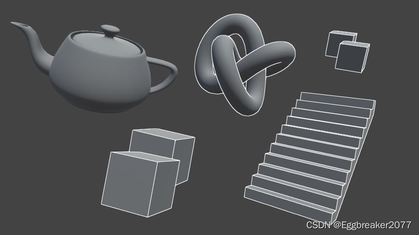
最近项目需要快速出一版卡通渲染风格进行吸量测试。但是原来的模型非常不适合使用back face 的描边方案(很难看),不得已寻求其他的描边方案,于是有了现在这篇基于法线和深度的后处理描边。
优点:
- 描边宽度一致。
- 重叠部分也能有描边。
- 不会出现断裂
缺点: - 后处理时有一定消耗(全屏采样8次)
本文是基于buildin 渲染管线,非URP。(老项目,没办法)
本文会使用自定义post-processing,目的是可以和其他的post-processing效果结合,方便使用。
不熟悉post-processing 的同学可以看下面这个文章:
PostProcessing的使用
自定义PostProcess
using System;
using UnityEngine;
using UnityEngine.Rendering.PostProcessing;

[Serializable]
[PostProcess(typeof(PostProcessOutlineRenderer), PostProcessEvent.BeforeStack, "Post Process Outline")]
public sealed class PostProcessOutline : PostProcessEffectSettings

    //声明变量
    public IntParameter scale = new IntParameter  value = 1 ;
    public FloatParameter  depthThreshold = new FloatParameter   value = 1 ;
    [Range(0, 1)]
    public FloatParameter normalThreshold = new FloatParameter  value = 0.4f ;
    [Range(0, 1)]
    public FloatParameter depthNormalThreshold = new FloatParameter  value = 0.5f ;
    public FloatParameter depthNormalThresholdScale = new FloatParameter  value = 7 ;
    public ColorParameter color = new ColorParameter  value = Color.white ;


public sealed class PostProcessOutlineRenderer : PostProcessEffectRenderer<PostProcessOutline>

    public override void Render(PostProcessRenderContext context)

    //将面板变量对Outline shader赋值
        var sheet = context.propertySheets.Get(Shader.Find("Hidden/Outline Post Process"));
        sheet.properties.SetFloat("_Scale", settings.scale);
        sheet.properties.SetFloat("_DepthThreshold", settings.depthThreshold);
        sheet.properties.SetFloat("_NormalThreshold", settings.normalThreshold);
        Matrix4x4 clipToView = GL.GetGPUProjectionMatrix(context.camera.projectionMatrix, true).inverse;
        sheet.properties.SetMatrix("_ClipToView", clipToView);
        sheet.properties.SetFloat("_DepthNormalThreshold", settings.depthNormalThreshold);
        sheet.properties.SetFloat("_DepthNormalThresholdScale", settings.depthNormalThresholdScale);
        sheet.properties.SetColor("_Color", settings.color);
        context.command.BlitFullscreenTriangle(context.source, context.destination, sheet, 0);
添加这个脚本后,我们就可以在PostProcess面板上进行输入参数控制
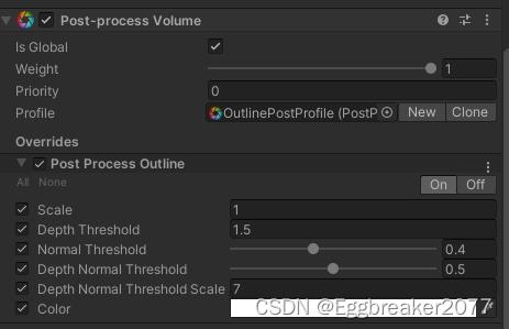
使用properties.SetXXX 将数据传入后处理Shader中
sheet.properties.SetFloat("_Scale", settings.scale);
后面Shader所使用的外部数据基本都由这里输入。
完整的Shader代码会放在最后。
OutlineShader关键代码说明
1 使用深度绘制描边
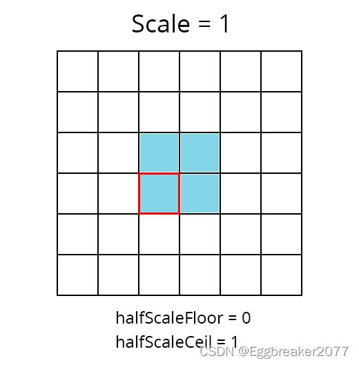
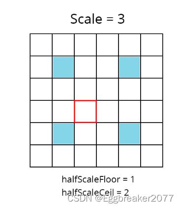
1.1 获得斜四方形UV坐标:
float halfScaleFloor = floor(_Scale * 0.5);
float halfScaleCeil = ceil(_Scale * 0.5);

float2 bottomLeftUV = i.texcoord - float2(_MainTex_TexelSize.x, _MainTex_TexelSize.y) * halfScaleFloor;
float2 topRightUV = i.texcoord + float2(_MainTex_TexelSize.x, _MainTex_TexelSize.y) * halfScaleCeil;
float2 bottomRightUV = i.texcoord + float2(_MainTex_TexelSize.x * halfScaleCeil, -_MainTex_TexelSize.y * halfScaleFloor);
float2 topLeftUV = i.texcoord + float2(-_MainTex_TexelSize.x * halfScaleFloor, _MainTex_TexelSize.y * halfScaleCeil);
i.texcoord 是屏幕UV
_Scale 是我们用来调整描边粗细的参数。通过floor 和ceil, 使得halfScaleFloor 和 halfScaleCeil 在调整_Scale时,以整数改变。通过这种方式,我们就可以让边缘检测像素以原UV位置向4个斜方向每次增加1像素。(因为深度和法线图是用point filtering采样的,不存在插值,所以我们使用整数增加)
1.2 采样四方向深度
float depth0 = SAMPLE_DEPTH_TEXTURE(_CameraDepthTexture, sampler_CameraDepthTexture, bottomLeftUV).r;
float depth1 = SAMPLE_DEPTH_TEXTURE(_CameraDepthTexture, sampler_CameraDepthTexture, topRightUV).r;
float depth2 = SAMPLE_DEPTH_TEXTURE(_CameraDepthTexture, sampler_CameraDepthTexture, bottomRightUV).r;
float depth3 = SAMPLE_DEPTH_TEXTURE(_CameraDepthTexture, sampler_CameraDepthTexture, topLeftUV).r;
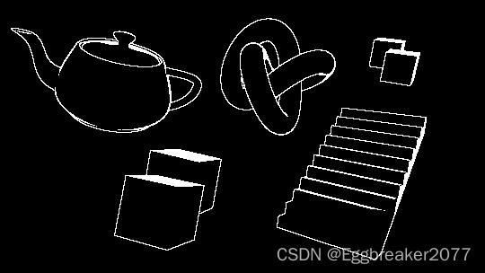
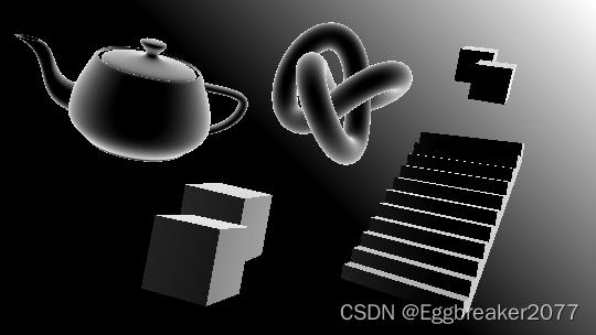
如果我们查看depth0的结果,可以看到下图
离摄像机越近,颜色越亮,越远则越暗。
这时我们就可以用两两深度图相减,这样两图深度相近的地方颜色值就非常小。深度差别大的地方则相反。
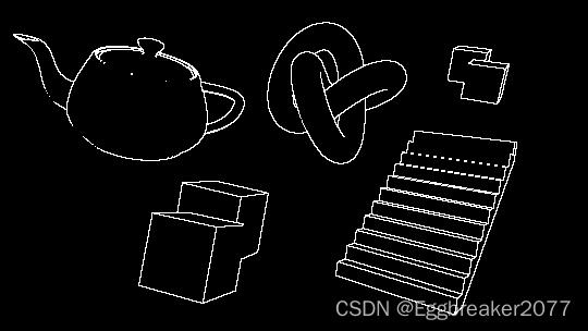
float depthFiniteDifference0 = depth1 - depth0;
float depthFiniteDifference1 = depth3 - depth2;

return abs(depthFiniteDifference0) * 100;//为了方便查看结果扩大100倍
得到下图:
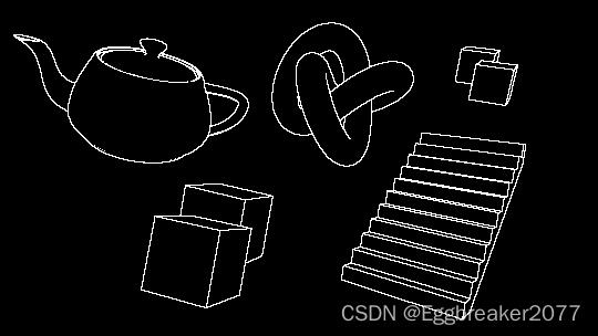
现在将两张深度图的平方相加再开方(The Roberts Cross 边缘检测方法)
float edgeDepth = sqrt(pow(depthFiniteDifference0, 2) + pow(depthFiniteDifference1, 2)) * 100;
return edgeDepth;
获得下图:
这个时候,一些外围边缘已经清晰可见。但是我们还是能在物体表面看到一些灰色区域。所以我们需要把较低的深度值过滤掉。
使用阈值_DepthThreshold
edgeDepth = edgeDepth > _DepthThreshold ? 1 : 0;
return edgeDepth;
在_DepthThreshold 值设定为0.2时,得到下图
这样,我们就解决了灰色区域。但是我们也注意到前方有一个Cube的顶部全部填充的白色,后方的两个Cube重叠区域没有描边,梯子和前方方块有些边缘没有绘制。
我们先解决后方Cube的问题。
因为深度值是非线性的,越到后面深度相差就越小。那么我们就要根据深度值改变阈值大小。
float depthThreshold = _DepthThreshold * depth0;
edgeDepth = edgeDepth > depthThreshold ? 1 : 0;
再将_DepthThreshold 改到1.5 我们可以看到
这样,后面重叠的Cube也能看到边缘了。
接下来我们要解决一些边缘缺失的问题。
2 使用法线绘制描边
为了获得所有物体法线数据,我们需要一个摄像机,来绘制法线图。然后将法线图保存到一个Shader全局变量中:_CameraNormalsTexture
为主摄像机添加脚本:
using UnityEngine;

public class RenderReplacementShaderToTexture : MonoBehaviour

    [SerializeField]
    Shader replacementShader;

    [SerializeField]
    RenderTextureFormat renderTextureFormat = RenderTextureFormat.ARGB32;

    [SerializeField]
    FilterMode filterMode = FilterMode.Point;

    [SerializeField]
    int renderTextureDepth = 24;

    [SerializeField]
    CameraClearFlags cameraClearFlags = CameraClearFlags.Color;

    [SerializeField]
    Color background = Color.black;

    [SerializeField]
    string targetTexture = "_RenderTexture";

    private RenderTexture renderTexture;
    private new Camera camera;

    private void Start()

        foreach (Transform t in transform)

            DestroyImmediate(t.gameObject);


        Camera thisCamera = GetComponent<Camera>();

        // Create a render texture matching the main camera's current dimensions.
        renderTexture = new RenderTexture(thisCamera.pixelWidth, thisCamera.pixelHeight, renderTextureDepth, renderTextureFormat);
        renderTexture.filterMode = filterMode;
        // Surface the render texture as a global variable, available to all shaders.
        Shader.SetGlobalTexture(targetTexture, renderTexture);

        // Setup a copy of the camera to render the scene using the normals shader.
        GameObject copy = new GameObject("Camera" + targetTexture);
        camera = copy.AddComponent<Camera>();
        camera.CopyFrom(thisCamera);
        camera.transform.SetParent(transform);
        camera.targetTexture = renderTexture;
        camera.SetReplacementShader(replacementShader, "RenderType");
        camera.depth = thisCamera.depth - 1;
        camera.clearFlags = cameraClearFlags;
        camera.backgroundColor = background;
通过SetReplacementShader,将场景中物体替换为绘制法线的Shader。得到法线图。
绘制法线Shader:
Shader "Hidden/Normals Texture"

    Properties


    SubShader

        Tags

			"RenderType" = "Opaque"


        Pass

            CGPROGRAM
            #pragma vertex vert
            #pragma fragment frag

            #include "UnityCG.cginc"

            struct appdata

                float4 vertex : POSITION;
				float3 normal : NORMAL;
            ;

            struct v2f

                float4 vertex : SV_POSITION;
				float3 viewNormal : NORMAL;
            ;

            sampler2D _MainTex;
            float4 _MainTex_ST;

            v2f vert (appdata v)

                v2f o;
                o.vertex = UnityObjectToClipPos(v.vertex);
                o.viewNormal = COMPUTE_VIEW_NORMAL;
				//o.viewNormal = mul((float3x3)UNITY_MATRIX_M, v.normal);
                return o;


            float4 frag (v2f i) : SV_Target

                return float4(normalize(i.viewNormal) * 0.5 + 0.5, 0);

            ENDCG
点击Play按钮,我们能在生成的法线摄像机中看到下图:

这时,我们就可以在Outline Shader中使用法线数据了。
同样,我们进行斜四方向采样。
float3 normal0 = SAMPLE_TEXTURE2D(_CameraNormalsTexture, sampler_CameraNormalsTexture, bottomLeftUV).rgb;
float3 normal1 = SAMPLE_TEXTURE2D(_CameraNormalsTexture, sampler_CameraNormalsTexture, topRightUV).rgb;
float3 normal2 = SAMPLE_TEXTURE2D(_CameraNormalsTexture, sampler_CameraNormalsTexture, bottomRightUV).rgb;
float3 normal3 = SAMPLE_TEXTURE2D(_CameraNormalsTexture, sampler_CameraNormalsTexture, topLeftUV).rgb;
然后继续使用The Roberts Cross 方法计算边缘:
float3 normalFiniteDifference0 = normal1 - normal0;
float3 normalFiniteDifference1 = normal3 - normal2;

float edgeNormal = sqrt(dot(normalFiniteDifference0, normalFiniteDifference0) + dot(normalFiniteDifference1, normalFiniteDifference1));
edgeNormal = edgeNormal > _NormalThreshold ? 1 : 0;

return edgeNormal;
由于 normalFiniteDifference0 是个float3 向量,所以使用点乘Dot来代替平方。得到下图:
可以看到,通过法线比较获得的边缘,不会有一块白的区域。
并且我们得到了一些深度检测没有获得的边缘。
现将两个结果合并:
float edge = max(edgeDepth, edgeNormal);
return edge;
得到下图:

3 解决倾斜表面白块问题
因为深度检测的原因,倾斜表面像素间会有很大的深度差。所以容易产生白块。为了解决这个问题,我们还需要知道摄像机到表面的方向(view direction 视方向)
3.1 计算视方向
由于我们采样的法线图是在视空间(view space),那么我们也需要在视空间的视方向。为了得到它,我们需要摄像机的 裁减到视空间(clip to view) 或者 逆投影(inverse projection) 矩阵。
但是这个矩阵在默认的屏幕shader中是不能获得的,所以我们通过C#将矩阵传递进来。
在custom postprocess中的代码:
Matrix4x4 clipToView = GL.GetGPUProjectionMatrix(context.camera.projectionMatrix, true).inverse;
sheet.properties.SetMatrix("_ClipToView", clipToView);
于是,我们就可以在vert着色器中计算视空间中的视方向了。
o.vertex = float4(v.vertex.xy, 0.0, 1.0);
o.viewSpaceDir = mul(_ClipToView, o.vertex).xyz;
3.2 使用视方向修正阈值
得到视方向后,我们就可以得到NdotV(也成为菲列尔),表示法线和视方向的重合度。
//法线在0...1范围, 视方向在 -1...1范围,需要统一范围
float3 viewNormal = normal0 * 2 - 1;
float NdotV = 1 - dot(viewNormal, -i.viewSpaceDir);

return NdotV;
得到下图:
我们引入阈值_DepthNormalThreshold 来控制NdotV的影响范围
同时引入_DepthNormalThresholdScale控制调节范围在0 - 1之间
float normalThreshold01 = saturate((NdotV - _DepthNormalThreshold) / (1 - _DepthNormalThreshold));
float normalThreshold = normalThreshold01 * _DepthNormalThresholdScale + 1;
然后将新的法线阈值和深度阈值结合:
float depthThreshold = _DepthThreshold * depth0 * normalThreshold;
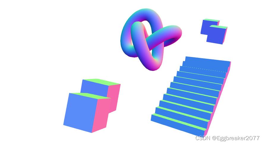
得到一个较完美的描边
最后合并图像原有颜色:
float4 color = SAMPLE_TEXTURE2D(_MainTex, sampler_MainTex, i.texcoord);
float4 edgeColor = float4(_Color.rgb, _Color.a * edge);

return alphaBlend(edgeColor, color);
得到最终效果图。
4 单独控制物体是否显示描边
因为是后处理,通常情况下,看到的物体都会被描边。但是我们有时候又需要排除一些不需要描边的物体。这时我们可以通过控制材质球的shaderPassEnable来实现。
public class ShaderPassController : MonoBehaviour

    public bool value;
    public string passName = "Always";
    // Start is called before the first frame update
    void Start()

        var mat = GetComponent<Renderer>().material;
        mat.SetShaderPassEnabled(passName, value);
用于绘制法线的Shader 没有声明Tag。此时,Unity会默认设置Tag“LightModel”=“Always”
此时,我们可以通过SetShaderPassEnabled 关闭Shader中Tag为"Always"的Pass. 关闭后,此物体的Shader对于法线摄像机等于没有任何Pass,所以不会被绘制。当我们给茶壶添加ShaderPassController脚本后,法线摄像机如下图:
如果物体原本的shader使用的是“Always”Tag,为了防止被关闭Pass,可以添加tags “LightModel”=“ForwardBase” 来规避
此时,我们只需判断没有法线数据的点就是没有描边就可以了。
if (normal3.r == 1 && normal3.g == 1 && normal3.b == 1
	&& normal0.r == 1 && normal0.g == 1 && normal0.b == 1
	&& normal1.r == 1 && normal1.g == 1 && normal1.b == 1
	&& normal2.r == 1 && normal2.g == 1 && normal2.b == 1)

		edge = 0;
得到下图:

OutlineShader完整代码
Shader "Hidden/Outline Post Process"
SubShader
Cull Off ZWrite Off ZTest Always
Pass
// Custom post processing effects are written in HLSL blocks,
// with lots of macros to aid with platform differences.
// https://github.com/Unity-Technologies/PostProcessing/wiki/Writing-Custom-Effects#shader
HLSLPROGRAM
#pragma vertex Vert
#pragma fragment Frag
#include "Packages/com.unity.postprocessing/PostProcessing/Shaders/StdLib.hlsl"
TEXTURE2D_SAMPLER2D(_MainTex, sampler_MainTex);
// _CameraNormalsTexture contains the view space normals transformed
// to be in the 0...1 range.
TEXTURE2D_SAMPLER2D(_CameraNormalsTexture, sampler_CameraNormalsTexture);
TEXTURE2D_SAMPLER2D(_CameraDepthTexture, sampler_CameraDepthTexture);
// Data pertaining to _MainTex's dimensions.
// https://docs.unity3d.com/Manual/SL-PropertiesInPrograms.html
float4 _MainTex_TexelSize;
float _Scale;
float _DepthThreshold;
float _NormalThreshold;
float4x4 _ClipToView;
float _DepthNormalThreshold;
float _DepthNormalThresholdScale;
float4 _Color;
// Combines the top and bottom colors using normal blending.
// https://en.wikipedia.org/wiki/Blend_modes#Normal_blend_mode
// This performs the same operation as Blend SrcAlpha OneMinusSrcAlpha.
float4 alphaBlend(float4 top, float4 bottom)
float3 color = (top.rgb * top.a) + (bottom.rgb * (1 - top.a));
float alpha = top.a + bottom.a * (1 - top.a);
return float4(color, alpha);
struct Varyings
float4 vertex : SV_POSITION;
float2 texcoord : TEXCOORD0;
float2 texcoordStereo : TEXCOORD1;
float3 viewSpaceDir : TEXCOORD2;
#if STEREO_INSTANCING_ENABLED
uint stereoTargetEyeIndex : SV_RenderTargetArrayIndex;
#endif
;
Varyings Vert(AttributesDefault v)
Varyings o;
o.vertex = float4(v.vertex.xy, 0.0, 1.0);
o.viewSpaceDir = mul(_ClipToView, o.vertex).xyz;
o.texcoord = TransformTriangleVertexToUV(v.vertex.xy);
#if