一种简单的三维重建算法的实现源码
Posted 新缸中之脑
tags:
篇首语:本文由小常识网(cha138.com)小编为大家整理,主要介绍了一种简单的三维重建算法的实现源码相关的知识,希望对你有一定的参考价值。
让我们从定义开始,三维重建 — 3d reconstruction — 是在长程数据处理的基础上开发对象的 3D 模型。可以使用多种原理进行三维重建:立体测量、立体光度测量、体积去除或运动数据。
本教程可以作为一个指南,解释了如何开发一个简单的应用程序来使用 GPU 重建对象的几何形状。
在上述原则中,我们选择了由Brian Cureless和Mark Levoy在其题为“ A Volumetric Method for Building Complex Models from Range Images ”的文章中提出的体积去除算法。
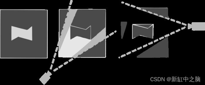
下图阐明了算法的基本原理。从一组图像中重建的3D对象显示在左侧。在处理图像时,该算法会移除位于对象前面的 3D 点(作者将结构光技术应用于深度映射)。第一次照片处理的结果显示在中心。使用从第二台相机获得的数据,程序删除额外的 3D 点。使用的角度越多,移除的额外 3D 点就越多;最后,只剩下属于该对象的点。

在应用程序中,我们实现了算法的简化版本,该算法仅删除图像中位于对象轮廓之外的点。继原文之后,我们将整个空间划分为一组立方元素(体素)。
为了确定体素是否属于 3D 对象,我们应用 GPU 渲染并将获得的投影与对象轮廓相匹配。
要获得投影,使用以下函数:
inline void	HComparator::render(HModel *model, const long long *voxel, HFrame *frame)
  pixelBuffer->makeCurrent();
  glClear(GL_COLOR_BUFFER_BIT);
  frame->setGL();
  float coords[3];
  model->position(voxel, coords);
  glTranslatef(coords[0], coords[1], coords[2]);
  double s = model->delta();
  glScalef(s, s, s);
  glCallList(voxelList);
  glFlush();
更详细地解释是,
pixelBuffer->makeCurrent () — 将绘图内容切换到屏幕外 QGLPixelBuffer缓冲区。
初始化输出缓冲区时,裁剪、深度测试和混合被禁用,因为唯一的目标是确定相对于对象的体素空间位置。
void	HComparator::initPixelBuffer()
  pixelBuffer->makeCurrent();
  glDisable(GL_CULL_FACE);
  glDisable(GL_DEPTH_TEST);
  glDisable(GL_LIGHTING);
  glDisable(GL_BLEND);
  glEnable(GL_VERTEX_ARRAY);
  glClearColor(1, 1, 1, 1);
  glColor3f(0, 0, 0);
  createVoxelList();
切换HComparator::render中的内容后,清空输出缓冲区并设置投影参数。
  glClear(GL_COLOR_BUFFER_BIT);
  frame->setGL();
  float coords[3];
  model->position(voxel, coords);
  glTranslatef(coords[0], coords[1], coords[2]);
  double s = model->delta();
  glScalef(s, s, s);
为了渲染体素,调用glCallList(voxelList)函数来执行预先形成的命令列表。初始化函数为:
void	HComparator::createVoxelList()
  float eps = 1e-4;
  static GLdouble vertices[]=
    0, 0, 0, 1, 0, 0,
    1, 1, 0, 0, 1, 0,
    0, 0, 1, 1, 0, 1,
    1, 1, 1, 0, 1, 1
  ;
  for (int i = 0; i < 24; i++)

    if (vertices[i] == 0)

      vertices[i] -= eps;

    if (vertices[i] == 1)

      vertices[i] += eps;


  static GLubyte indices[]=
    0, 3, 2, 1, 2, 3, 7, 6,
    0, 4, 7, 3, 1, 2, 6, 5,
    4, 5, 6, 7, 0, 1, 5, 4
  ;
  voxelList=glGenLists(1);
  glVertexPointer(3, GL_DOUBLE, 0, vertices);
  glMatrixMode(GL_MODELVIEW);
  glNewList(voxelList, GL_COMPILE);
  glDrawElements(GL_QUADS, 24, GL_UNSIGNED_BYTE, indices);
  glEndList();
绘制后,使用HComparator::compareData函数确定相对于对象的体素空间位置。
char HComparator::compareData(HModel *model, const long long *voxel, HFrame* frame)
int min_x, min_y, max_x, max_y;
long int width, _width, height;
auto image=frame->data;
getBounds(min_x, min_y, max_x, max_y, frame->width, frame->height);
width=max_x-min_x;
height=max_y-min_y;
if ((width == 0) || (height == 0))
return 4;
_width=width;
if(_width%4)
_width+=4-_width%4;
glReadPixels(min_x, min_y, width, height, GL_RED, GL_UNSIGNED_BYTE, currentData);
char result=4;
for(int j=0; j<height; j++)
auto data_ptr = ¤tData[j*_width];
auto image_ptr = &image[(min_y + j)*frame->width + min_x];
for(auto i=0; i<width; i++)
if(data_ptr[i] == 0)
if(image_ptr[i] != 0)
if(result==1)
return 2;
result=0;
else
if(result==0)
return 2;
result=1;
return result;
compareData函数复制缓冲区内容并根据三个可能的选项将其与对象轮廓进行比较(见下图):
a) 体素完全位于对象内(代码 1);
b) 体素属于边界(代码2);
c) 体素完全位于对象之外(代码 0)。

用于开发 3D 模型的角度集由HReconstruction::process函数顺序处理。我们从每个体素都属于对象的假设开始。如果确定体素位置超出对象的某个角度,则其处理停止并从模型中移除。执行整个处理,直到考虑所有角度。最后,只剩下属于对象模型的体素。
void	HReconstruction::process()
  int idle_counter = 0;
  _voxel[0] = _voxel[0]%_model->N();
  _voxel[1] = _voxel[1]%_model->N();
  _voxel[2] = _voxel[2]%_model->N();

  for (; _voxel[0] < _model->N(); _voxel[0]++)
    for (; _voxel[1] < _model->N(); _voxel[1]++)
      for (; _voxel[2] < _model->N(); _voxel[2]++)
        char voxel_type = 1;
        for (auto &frame: _model->frames())
          char t=_comparator->compare(_model, _voxel, frame);
          if ((t == 0) || (t == 4))
            voxel_type = 0;
            break;


        _model->setStatus(_voxel, voxel_type);
        if(idle_counter++>idleValue)
          return;

      _voxel[2] = 0;

    _voxel[1] = 0;

  workFlag=0;
为了匹配体素和对象轮廓,应该知道投影参数。它们由GL_PROJECTION和GL_MODELVIEW矩阵定义(参见setGL函数)。
void	HFrame::setGL()
  glMatrixMode(GL_PROJECTION);
  glViewport(0, 0, width, height);
  glLoadMatrixd((double*)intrisicParameters.data);
  glMatrixMode(GL_MODELVIEW);
  glLoadIdentity();
  glLoadMatrixd((double*)modelviewMatrix.data);
GL_PROJECTION矩阵由相机参数定义,特别是焦距和图像大小(HFrame::loadIntrisicParameters函数)。
void HFrame::loadIntrisicParameters(const Mat &img, double focal_length)

  // http://kgeorge.github.io/2014/03/08/calculating-opengl-perspective-matrix-from-opencv-intrinsic-matrix/
  Mat_<double> persp(4,4); persp.setTo(0);
  double f = focalLengthToPixels(focal_length, img.rows);
  double fx = f;
  double fy = f;
  double cx = img.cols/(double)2;
  double cy = img.rows/(double)2;
  persp(0,0) = fx/cx;
  persp(1,1) = fy/cy;
  double near = 0.01;
  double far = 1000;

  persp(2,2) = -(far+near)/(far-near);
  persp(2,3) = -2.0*far*near / (far-near);
  persp(3,2) = -1.0;

  persp = persp.t(); //to col-major for OpenGL

  intrisicParameters = persp.clone();
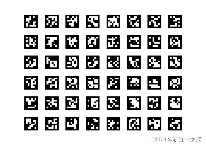
可以使用增强现实标记来确定相机的 3D 位置,我们从 aruco 库中获取它。标记是要打印在一张纸上的特殊图像(见下图)。

拍摄物体时,标记必须保持不动,并在每张物体照片中进入相机视野。

该库检测标记控制点,然后使用相机焦距计算标记 3D 位置(rvec和tvec)。
auto arucoDict = cv::aruco::getPredefinedDictionary(cv::aruco::DICT_6X6_250);
  auto grid = cv::aruco::GridBoard::create(6, 8, 0.04, 0.02, arucoDict);
  Mat gray;
  vector<Mat> board_corners;
  Mat board_ids;
  cvtColor(img_bgr, gray, COLOR_BGR2GRAY);
  cv::aruco::detectMarkers(gray, arucoDict, board_corners, board_ids);
  if (board_corners.empty())

    return false;

  double pixelsFocalLength = focalLengthToPixels(focalLength, img_bgra.rows);
  cameraMatrix = (Mat_<double>(3, 3)<< pixelsFocalLength, 0, img_bgra.cols*0.5, 0, pixelsFocalLength, img_bgra.rows*0.5, 0, 0, 1);

  cv::aruco::estimatePoseBoard(board_corners, board_ids, grid, cameraMatrix, Mat(), rvec, tvec);
  loadExtrisicParameters(rvec, tvec, modelviewMatrix);
rvec和tvec参数确定GL_MODELVIEW矩阵(参见HFrame ::loadExtrisicParameters函数)。
void HFrame::loadExtrisicParameters(const Mat &Rvec, const Mat &Tvec, Mat &modelview_matrix)

  // http://kgeorge.github.io/2014/03/08/calculating-opengl-perspective-matrix-from-opencv-intrinsic-matrix/
  CV_Assert(Rvec.rows == 3);
  CV_Assert(Tvec.rows == 3);
  Mat Rot(3,3,CV_32FC1);
  Rodrigues(Rvec, Rot);

  // [R | t] matrix
  Mat_<double> para = Mat_<double>::eye(4,4);
  Rot.convertTo(para(Rect(0,0,3,3)),CV_64F);
  Tvec.copyTo(para(Rect(3,0,1,3)));

  Mat cvToGl = Mat::zeros(4, 4, CV_64F);
  cvToGl.at<double>(0, 0) = 1.0f;
  cvToGl.at<double>(1, 1) = -1.0f; // Invert the y axis
  cvToGl.at<double>(2, 2) = -1.0f; // invert the z axis
  cvToGl.at<double>(3, 3) = 1.0f;

  para = cvToGl * para;

  Mat(para.t()).copyTo(modelview_matrix); // transpose to col-major for OpenGL
至此,我们学会了如何在图像平面上投影体素,确定体素相对于物体图像的位置,计算投影参数,并通过处理来自多个摄像机的数据来确定体素是否属于物体体;这是一种用于重建 3D 对象的简化但完整的技术,源代码可以在这里下载。
原文链接:简单三维重建实现 — BimAnt
以上是关于一种简单的三维重建算法的实现源码的主要内容,如果未能解决你的问题,请参考以下文章