ESP32上手笔记 | 05 - 获取MPU6050数据进行姿态解算和展示(I2Cdev+MPU6050+Processing)
Posted Mculover666
tags:
篇首语:本文由小常识网(cha138.com)小编为大家整理,主要介绍了ESP32上手笔记 | 05 - 获取MPU6050数据进行姿态解算和展示(I2Cdev+MPU6050+Processing)相关的知识,希望对你有一定的参考价值。
一、MPU6050陀螺仪加速度计传感器
1. 介绍
MPU6050是一个带有3轴加速度计和3轴陀螺仪的传感器,也称之为惯性测量单元(IMU)传感器:
陀螺仪测量回转的速度(rad/s),是在X、Y、Z三个轴的角位置变化,分别称为roll、pitch、yaw,这可以使我们判断物体的朝向:
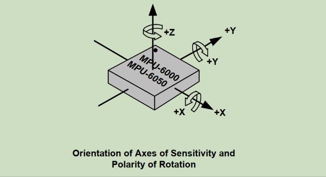
加速度计用来测量加速度,也就是物体速度的变化率。
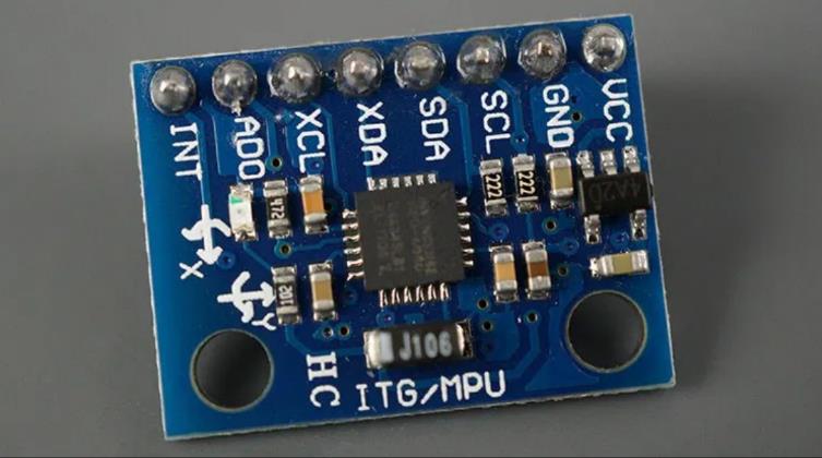
2. 模块引脚说明
- VCC:3.3V
- GND
- SCL:用于I2C通信
- SDA:用于I2C通信
- XDA:用来连接其它的I2C传感器到MPU6050
- XCL:用来连接其它的I2C传感器到MPU6050
- AD0:用来设置I2C从机地址
- INT:中断引脚,用来表示有新的测量数据可用
3. I2C通信协议
MPU6050的I2C从机地址是110100X,7bit长度,最低位X由AD0引脚来控制。
MPU6050支持的最大I2C速度为400kHz。
二、i2cdevlib
I2C Device Library(i2cdevlib)是一组基本统一且文档良好的类的集合,为I2C设备提供简单直观的接口。
1. 安装库
Github仓库地址:https://github.com/jrowberg/i2cdevlib
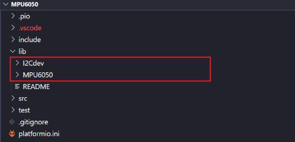
拉取到之后,将其中Arduino下的I2Cdev文件夹和MPU6050文件夹复制到platformIO工程的lib路径中。
2. 使用库
包含头文件:
#include "I2Cdev.h"
#include "MPU6050.h"
2.1. 创建MPU6050对象
MPU6050_Base(uint8_t address=MPU6050_DEFAULT_ADDRESS, void *wireObj=0);
构造函数中address参数是指MPU6050的从机地址,
默认是0x68(AD0引脚为低电平),如果AD0引脚接为高电平,可以指定地址为0x69。
2.2. 初始化
/** Power on and prepare for general usage.
 * This will activate the device and take it out of sleep mode (which must be done
 * after start-up). This function also sets both the accelerometer and the gyroscope
 * to their most sensitive settings, namely +/- 2g and +/- 250 degrees/sec, and sets
 * the clock source to use the X Gyro for reference, which is slightly better than
 * the default internal clock source.
 */
void MPU6050_Base::initialize();
2.3. 测试通信是否正常
/** Verify the I2C connection.
 * Make sure the device is connected and responds as expected.
 * @return True if connection is valid, false otherwise
 */
bool MPU6050_Base::testConnection()
    return getDeviceID() == 0x34;
2.4. 获取六轴数据
/** Get raw 6-axis motion sensor readings (accel/gyro).
 * Retrieves all currently available motion sensor values.
 * @param ax 16-bit signed integer container for accelerometer X-axis value
 * @param ay 16-bit signed integer container for accelerometer Y-axis value
 * @param az 16-bit signed integer container for accelerometer Z-axis value
 * @param gx 16-bit signed integer container for gyroscope X-axis value
 * @param gy 16-bit signed integer container for gyroscope Y-axis value
 * @param gz 16-bit signed integer container for gyroscope Z-axis value
 * @see getAcceleration()
 * @see getRotation()
 * @see MPU6050_RA_ACCEL_XOUT_H
 */
void MPU6050_Base::getMotion6(int16_t* ax, int16_t* ay, int16_t* az, int16_t* gx, int16_t* gy, int16_t* gz);
三、获取MPU6050原始数据
1. 硬件连接

2. 代码编写
#include <Arduino.h>
#include "I2Cdev.h"
#include "MPU6050.h"
#include "Wire.h"

class IMU
    private:
        MPU6050 imu;
        int16_t ax, ay, az;
        int16_t gx, gy, gz;
        int16_t temperature;
    public:
        int init();
        void update();

        int16_t getAccelX();
        int16_t getAccelY();
        int16_t getAccelZ();

        int16_t getGyroX();
        int16_t getGyroY();
        int16_t getGyroZ();

        int16_t getTemperature();
;

IMU imu;

void setup()
    Serial.begin(115200);
    imu.init();


void loop()
    imu.update();

    // display tab-separated accel/gyro x/y/z values
    Serial.print("a/g/t:\\t");
    Serial.print(imu.getAccelX()); Serial.print("\\t");
    Serial.print(imu.getAccelY()); Serial.print("\\t");
    Serial.print(imu.getAccelZ()); Serial.print("\\t");
    Serial.print(imu.getGyroX()); Serial.print("\\t");
    Serial.print(imu.getGyroY()); Serial.print("\\t");
    Serial.print(imu.getGyroZ()); Serial.print("\\t");
    Serial.println(imu.getTemperature());

    delay(100);


int IMU::init()

    // initialize i2c
    Wire.begin();
    Wire.setClock(400000);

    // initialize device
    Serial.println("Initializing I2C devices...");
    imu.initialize();

    // verify connection
    Serial.println("Testing device connections...");
    if (imu.testConnection())
        Serial.println("MPU6050 connection successful");
        return 0;
     else
        Serial.println("MPU6050 connection failed");
        return -1;


void IMU::update()

    // read raw accel/gyro measurements from device
    imu.getMotion6(&ax, &ay, &az, &gx, &gy, &gz);

    // read temperature
    temperature = imu.getTemperature();


int16_t IMU::getAccelX()

    return ax;


int16_t IMU::getAccelY()

    return ay;


int16_t IMU::getAccelZ()

    return az;


int16_t IMU::getGyroX()

    return gx;


int16_t IMU::getGyroY()

    return gy;


int16_t IMU::getGyroZ()

    return gz;


int16_t IMU::getTemperature()

    return temperature;
3. 测试结果

四、获取MPU6050 DMP姿态解算数据
1. 姿态解算
2. 硬件连接
添加 引脚GPIO16用来连接MPU6050中断引脚:
3. 代码编写
#include <Arduino.h>
#include "I2Cdev.h"
#include "MPU6050_6Axis_MotionApps20.h"
#include "Wire.h"

#define INTERRUPT_PIN   16

class IMU
    private:
        MPU6050 imu;
        float euler[3];         // [psi, theta, phi]    Euler angle container
        float ypr[3];           // [yaw, pitch, roll]   yaw/pitch/roll container and gravity vector
        int16_t temperature;

        // MPU control/status vars
        bool dmpReady = false;  // set true if DMP init was successful

    public:
        int init(uint8_t pin);
        void update();

        float getYaw();
        float getPitch();
        float getRoll();

        int16_t getTemperature();
;

IMU imu;

volatile bool mpuInterrupt = false;     // indicates whether MPU interrupt pin has gone high
void dmpDataReady()
    mpuInterrupt = true;


void setup()
    Serial.begin(115200);
    imu.init(INTERRUPT_PIN);


void loop()
    imu.update();

    Serial.print("ypr\\t");
    Serial.print(imu.getYaw());
    Serial.print("\\t");
    Serial.print(imu.getPitch());
    Serial.print("\\t");
    Serial.println(imu.getRoll());

    delay(100);


int IMU::init(uint8_t pin)

    uint8_t mpuIntStatus;   // holds actual interrupt status byte from MPU
    uint8_t devStatus;      // return status after each device operation (0 = success, !0 = error)
    uint16_t packetSize;    // expected DMP packet size (default is 42 bytes)

    // initialize i2c
    Wire.begin();
    Wire.setClock(400000);

    // initialize device
    Serial.println("Initializing I2C devices...");
    imu.initialize();

    // verify connection
    Serial.println("Testing device connections...");
    if (imu.testConnection())
        Serial.println("MPU6050 connection successful");
     else
        Serial.println("MPU6050 connection failed");
        return -1;


    pinMode(pin, INPUT);

    // load and configure the DMP
    devStatus = imu.dmpInitialize();

    // supply your own gyro offsets here, scaled for min sensitivity
    imu.setXGyroOffset(220);
    imu.setYGyroOffset(76);
    imu.setZGyroOffset(-85);
    imu.setZAccelOffset(1788); // 1688 factory default for my test chip

    // make sure it worked (returns 0 if so)
    if (devStatus == 0)
        // Calibration Time: generate offsets and calibrate our MPU6050
        imu.CalibrateAccel(6);
        imu.CalibrateGyro(6);
        imu.PrintActiveOffsets();
        // turn on the DMP, now that it's ready
        Serial.println(F("Enabling DMP..."));
        imu.setDMPEnabled(true);

        // enable Arduino interrupt detection
        Serial.print(F("Enabling interrupt detection (Arduino external interrupt "));
        Serial.print(digitalPinToInterrupt(INTERRUPT_PIN));
        Serial.println(F(")..."));
        attachInterrupt(digitalPinToInterrupt(INTERRUPT_PIN), dmpDataReady, RISING);
        mpuIntStatus = imu.getIntStatus();

        // set our DMP Ready flag so the main loop() function knows it's okay to use it
        Serial.println(F("DMP ready! Waiting for first interrupt..."));
        dmpReady = true;

        // get expected DMP packet size for later comparison
        packetSize = imu.dmpGetFIFOPacketSize();
     else
        // ERROR!
        // 1 = initial memory load failed
        // 2 = DMP configuration updates failed
        // (if it's going to break, usually the code will be 1)
        Serial.print(F("DMP Initialization failed (code "));
        Serial.print(devStatus);
        Serial.println(F(")"));


void IMU::update()

    // orientation/motion vars
    Quaternion q;           // [w, x, y, z]         quaternion container
    VectorInt16 aa;         // [x, y, z]            accel sensor measurements
    VectorInt16 aaReal;     // [x, y, z]            gravity-free accel sensor measurements
    VectorInt16 aaWorld;    // [x, y, z]            world-frame accel sensor measurements
    VectorFloat gravity;    // [x, y, z]            gravity vector

    // MPU control/status vars
    uint8_t fifoBuffer[64]; // FIFO storage buffer

    // if programming failed, don't try to do anything
    if (!dmpReady) return;

    // read a packet from FIFO
    if (imu.dmpGetCurrentFIFOPacket(fifoBuffer))  // Get the Latest packet
         // display Euler angles in degrees
            imu.dmpGetQuaternion(&q, fifoBuffer);
            imu.dmpGetGravity(&gravity, &q);
            imu.dmpGetYawPitchRoll(ypr, &q, &gravity);


    // read temperature
    temperature = imu.getTemperature();


float IMU::getYaw()

    return ypr[0] * 180/M_PI;


float IMU::getPitch()

    return ypr[1] * 180/M_PI;


float IMU::getRoll()

    return ypr[2] * 180/M_PI;


int16_t IMU::getTemperature()

    return temperature;
4. 测试结果

五、使用Processing进行姿态可视化
1. 安装Processing
下载地址:https://processing.org/download。
2. 安装toxiclibs库

3. 修改数据打印格式
添加格式定义:
// packet structure for InvenSense teapot demo
uint8_t teapotPacket[14] =  '$', 0x02, 0,0, 0,0, 0,0, 0,0, 0x00, 0x00, '\\r', '\\n' ;
删除之前的打印格式:
Serial.print("ypr\\t");
Serial.print(imu.getYaw());
Serial.print("\\t");
Serial.print(imu.getPitch());
Serial.print("\\t");
Serial.println(imu.getRoll());
新增一个IMU类的发送数据函数:
void IMU::sendDataToProcessing()

    // display quaternion values in InvenSense Teapot demo format:
    teapotPacket[2] = fifoBuffer[0];
    teapotPacket[3] = fifoBuffer[1];
    teapotPacket[4] = fifoBuffer[4];
    teapotPacket[5] = fifoBuffer[5];
    teapotPacket[6] = fifoBuffer[8];
    teapotPacket[7] = fifoBuffer[9];
    teapotPacket[8] = fifoBuffer[12];
    teapotPacket[9] = fifoBuffer[13];
    Serial.write(teapotPacket, 14);
    teapotPacket[11]++; // packetCount, loops at 0xFF on purpose
在update函数调用之后,调用该函数发送数据到上位机。
修改完毕,烧录代码。
4. 运行processing上位机
上位机为lib\\MPU6050\\examples\\MPU6050_DMP6\\Processing\\MPUTeapot\\MPUTeapot.pde,使用processing打开。
修改连接ESP32的串口:


以上是关于ESP32上手笔记 | 05 - 获取MPU6050数据进行姿态解算和展示(I2Cdev+MPU6050+Processing)的主要内容,如果未能解决你的问题,请参考以下文章