VSCode PlatformIO STC单片机开发头文件制作与添加方法
Posted perseverance52
tags:
篇首语:本文由小常识网(cha138.com)小编为大家整理,主要介绍了VSCode PlatformIO STC单片机开发头文件制作与添加方法相关的知识,希望对你有一定的参考价值。
【VSCode PlatformIO】 STC单片机开发头文件制作与添加方法
本着授人以鱼不如授人以渔的精神,今天教大家如何制作基于VSCode PlatformIO平台开发STC系列单片机头文件制作以及添加方法。
STC系列头文件准备
- STC系列头文件获取途径:
-
- 通过STC官方工具
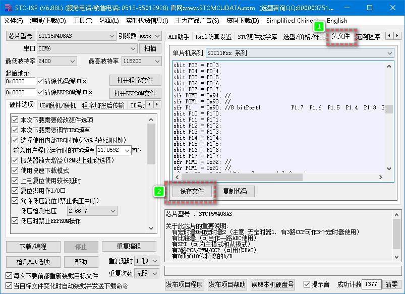
STC-ISP,找到自己所需型号的头文件,点击下面的“保存文件”按钮进行保存。格式是后缀带.h的格式。

- 通过STC官方工具
开始头文件转换工作
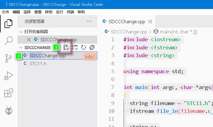
- 新建一个VSCode项目文件夹,名字随便自己爱好随便取。将上面保存下来的头文件放到这个文件夹里面。

- 在项目文件夹上鼠标右键,通过
VSCode打开。

- 在项目里面新建一个后缀名为
.cpp的文件。
.
- 在
.cpp文件内添加如下代码:
注意:修改string filename = "STC11.h";//这里填写同目录里的STC头文件名称,包含后缀名。
#include <iostream>
#include <fstream>
#include <string>

using namespace std;

int main(int argc, char *args[])

  string filename = "STC11.h";//这里填写同目录里的STC头文件名称包含后缀名。
  ifstream file_in(filename.c_str());

  string s;
  string previous_addr;
  while (getline(file_in, s))

    if (s[0] == '/' || s[0] == '#')
      cout << s << endl;
    else if (s.length() > 4)

      string::size_type type_end = s.find_first_of(' ');
      string type = s.substr(0, type_end);

      string::size_type name_begin = s.find_first_not_of(' ', type_end);
      string::size_type name_end = s.find_first_of(' ', name_begin);
      string name = s.substr(name_begin, name_end - name_begin);

      string::size_type addr_begin = s.find_first_not_of(" =", name_end);
      string::size_type addr_end = s.find_first_of(" ;", addr_begin);
      string addr = s.substr(addr_begin, addr_end - addr_begin);

      string comment;
      bool haveComment = true;
      if (addr_end == s.length() - 1)

        haveComment = false;


      if (haveComment)

        string::size_type comment_begin = s.find_first_not_of("; ", addr_end);
        comment = s.substr(comment_begin);


      if (type == "sfr")

        cout << "SFR(" << name << ", " << addr << ");";
        if (haveComment)
          cout << comment;
        cout << endl;
        previous_addr = addr;

      else if (type == "sbit")

        string bit_offset = addr.substr(addr.length() - 1);

        cout << "SBIT(" << name << ", " << previous_addr << ", " << bit_offset << ");";
        if (haveComment)
          cout << comment;
        cout << endl;


  return 0;
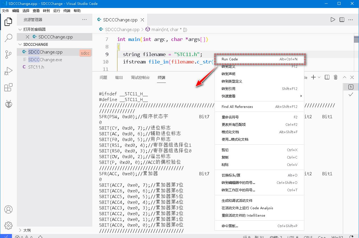
- 在代码编辑区域内,鼠标右键-
Run Code.,在调试终端将输出转换后的信息,将其全部复制保存为所需要的SDCC头文件名称。

VSCode编译运行所依赖的插件需要自己下载。(没记错的话应该必须安装下面这两个。)

- 完善头文件,在头文件前面补充几个引用头文件,以方便主程序调用,消除引用异常而导致关键字上出现
波浪线。
#include <8051.h>
#include <compiler.h>
#include <stdbool.h>
#ifdef REG8051_H
#undef REG8051_H
#endif
- 将完善的头文件保存到
VSCode PlatformIO的SDCC目录对应的单片机目录下面:
例如我的电脑所在位置:
C:\\Users\\Administrator\\.platformio\\packages\\toolchain-sdcc\\include\\mcs51
- 如果是安装的独立SDCC编译器的话,就放置
mcs51目录下面:
例如我的电脑安装的位置:
D:\\Program Files\\SDCC\\include\\mcs51
例如我转换后的STC11.h头文件
基本上一次到位,主要是注释内容有些是换行的内容做一下调整就可以了,需要处理的基本都处理了。
/*------------------------------------------------*/
/* --- 宏晶科技 STCMCU ---------------------------*/
/* --- Mobile: (86)13922805190 -------------------*/
/* --- Fax: 86-755-82944243 ----------------------*/
/* --- Tel: 86-755-82948412 ----------------------*/
/* --- Web: www.STCMCU.com -----------------------*/
/* 适用于: STC11Fxx STC11Lxx -------------------*/
/* ------- STC11FxxX STC11LxxX ------------------*/
/* ------- STC11FxxE STC11LxxE ------------------*/
/* ------- STC11FxxXE STC11LxxXE -----------------*/
/* ------- IAP11Fxx IAP11Lxx ------------------*/
/* ------- IAP11FxxE IAP11LxxE ------------------*/
/* ------- IAP11FxxXE IAP11LxxXE -----------------*/
/*------------------------------------------------*/
#ifndef __STC11_H__
#define __STC11_H__
#include <8051.h>
#include <compiler.h>
#include <stdbool.h>
#ifdef REG8051_H
#undef REG8051_H
#endif
SFR(PSW, 0xd0);//程序状态字 Bit7 Bit6 Bit5 Bit4 Bit3 Bit2 Bit1 Bit0
SBIT(CY, 0xd0, 7);//进位标志
SBIT(AC, 0xd0, 6);//辅助进位标志
SBIT(F0, 0xd0, 5);//用户标志
SBIT(RS1, 0xd0, 4);//寄存器组选择位1
SBIT(RS0, 0xd0, 3);//寄存器组选择位0
SBIT(OV, 0xd0, 2);//溢出标志
SBIT(P, 0xd0, 0);//ACC的偶校验位
/
SFR(ACC, 0xe0);//累加器 Bit7 Bit6 Bit5 Bit4 Bit3 Bit2 Bit1 Bit0
SBIT(ACC7, 0xe0, 7);//累加器第7位
SBIT(ACC6, 0xe0, 6);//累加器第6位
SBIT(ACC5, 0xe0, 5);//累加器第5位
SBIT(ACC4, 0xe0, 4);//累加器第4位
SBIT(ACC3, 0xe0, 3);//累加器第3位
SBIT(ACC2, 0xe0, 2);//累加器第2位
SBIT(ACC1, 0xe0, 1);//累加器第1位
SBIT(ACC0, 0xe0, 0);//累加器第0位
/
SFR(B, 0xf0);//B寄存器 Bit7 Bit6 Bit5 Bit4 Bit3 Bit2 Bit1 Bit0
/
SFR(SP, 0x81);//堆栈指针 Bit7 Bit6 Bit5 Bit4 Bit3 Bit2 Bit1 Bit0/
SFR(DPL, 0x82);//数据指针低字节 Bit7 Bit6 Bit5 Bit4 Bit3 Bit2 Bit1 Bit0
/
SFR(DPH, 0x83);//数据指针高字节 Bit7 Bit6 Bit5 Bit4 Bit3 Bit2 Bit1 Bit0
SFR(PCON, 0x87);//电源控制寄存器 Bit7 Bit6 Bit5 Bit4 Bit3 Bit2 Bit1 Bit0
#define SMOD 0x80 //串口波特率倍速位,置1可使波特率快1倍
#define SMOD0 0x40 //FE/SM0选择位,0:SCON.7为SM0 1:SCON.7为FE
#define LVDF 0x20 //低压检测中断请求位,由硬件置1,需由软件清0
#define POF 0x10 //上电复位标志位,上电时由硬件置1,需由软件清0
#define GF1 0x08 //通用标志位1
#define GF0 0x04 //通用标志位0
#define PD 0x02 //掉电控制位,写1可以使MCU进入PowerDown模式
#define IDL 0x01 //空闲控制位,写1可以使MCU进入Idle模式
/
SFR(WAKE_CLKO, 0x8f);//掉电唤醒/时钟输出控制 Bit7 Bit6 Bit5 Bit4 Bit3 Bit2 Bit1 Bit0
#define RXD_PIN_IE 0x40 //允许RXD(P3.0)下降沿置位RI中断时唤醒掉电MCU(必须打开相应中断)
#define T1_PIN_IE 0x20 //允许T1(P3.5)下降沿置位T1中断时唤醒掉电MCU(必须打开相应中断)
#define T0_PIN_IE 0x10 //允许T0(P3.4)下降沿置位T0中断时唤醒掉电MCU(必须打开相应中断)
#define BRTCLKOEN 0x04 //打开P1.0脚的BRT时钟溢出脉冲,输出的时钟频率为1/2倍的BRT溢出率
#define T1CLKOEN 0x02 //打开P3.5脚的定时器1时钟溢出脉冲,输出的时钟频率为1/2倍的T1溢出率
#define T0CLKOEN 0x01 //打开P3.4脚的定时器0时钟溢出脉冲,输出的时钟频率为1/2倍的T0溢出率
/
SFR(CLK_DIV, 0x97);//时钟分频寄存器 Bit7 Bit6 Bit5 Bit4 Bit3 Bit2 Bit1
Bit0
#define FOSCD1 0x00 //系统时钟为Fosc
#define FOSCD2 0x01 //系统时钟为Fosc/2
#define FOSCD4 0x02 //系统时钟为Fosc/4
#define FOSCD8 0x03 //系统时钟为Fosc/8
#define FOSCD16 0x04 //系统时钟为Fosc/16
#define FOSCD32 0x05 //系统时钟为Fosc/32
#define FOSCD64 0x06 //系统时钟为Fosc/64
#define FOSCD128 0x07 //系统时钟为Fosc/128
/
SFR(BUS_SPEED, 0xa1);//数据总线速度控制器 Bit7 Bit6 Bit5 Bit4 Bit3 Bit2 Bit1
Bit0
#define ALES1 0x20 //P0地址建立时间和保持时间到ALE信号的下降沿的时钟数
#define ALES0 0x10 //ALES1/ALES0=0/0:1个时钟 0/1:2个时钟 1/0:3个时钟 1/1:4个时钟
#define RWS2 0x04 //MOVX指令的时钟数
#define RWS1 0x02 //RWS2/RWS1/RWS0=000:1个时钟 001:2个时钟 010:3个时钟 011:4个时钟
#define RWS0 0x01 // 100:5个时钟 101:6个时钟 110:7个时钟 111:8个时钟
/
SFR(WKTCL, 0xaa);//掉电唤醒定时器低字节 Bit7 Bit6 Bit5 Bit4 Bit3 Bit2 Bit1 Bit0
/
SFR(WKTCH, 0xab);//掉电唤醒定时器高字节 Bit7 Bit6 Bit5 Bit4 Bit3 Bit2 Bit1 Bit0
#define WKTEN 0x80 //掉电唤醒定时器使能位,置1时,当CPU进入掉电模式后开始计时,计时单周
期约为560us,最大可计4095次(大约2.3s)
/
SFR(WDT_CONTR, 0xc1);//看门狗定时器控制器 Bit7 Bit6 Bit5 Bit4 Bit3 Bit2 Bit1
Bit0
#define WDT_FLAG 0x80 //看门狗复位标志,当看门狗溢出产生复位后,硬件自动置1,需要由软件清0
#define EN_WDT 0x20 //软件使能看门狗,打开后不能用软件的方式关闭
#define CLR_WDT 0x10 //清看门狗定时器
#define IDLE_WDT 0x08 //IDLE模式下,看门狗定时器是否继续计时
SFR(AUXR, 0x8e);//辅助寄存器 Bit7 Bit6 Bit5 Bit4 Bit3 Bit2 Bit1 Bit0
#define T0x12 0x80 //定时器0时钟控制,0:Fosc/12(传统的12分频) 1:Fosc/1(1T模式,不分频, 即12倍于传统速度)
#define T1x12 0x40 //定时器1时钟控制,0:Fosc/12(传统的12分频) 1:Fosc/1(1T模式,不分频, 即12倍于传统速度)
#define UR0x6 0x20 //串口模式0的时钟控制,0:Fosc/12(传统的12分频) 1:Fosc/2(2分频,,即6倍于传统速度)
#define BRTR 0x10 //独立波特率发生器启动控制位,1:启动独立波特率发生器 0:停止独立波特率发生器
#define BRTx12 0x04 //独立波特率发生器时钟控制,0:Fosc/12(传统的12分频) 1:Fosc/1(1T模式,不分频,即12倍于传统速度)
#define EXTRAM 0x02 //内部扩展RAM禁能位,0:内部扩展RAM有效 1:禁用内部扩展RAM
#define S1BRS 0x01 //串口1的波特率发生器选择位,0:定时器1 1:独立波特率发生器(注意串口2只能够使用独立波特率发生器)
/
SFR(AUXR1, 0xa2);//辅助寄存器1 Bit7 Bit6 Bit5 Bit4 Bit3 Bit2 Bit1 Bit0
#define UAER_P1 0x80 //将串口映射到P1口,0:RXD(P3.0)TXD(P3.1) 1:RXD2(P1.6)TXD2(P1.7)
#define GF2 0x08 //通用标志位2
#define DPS 0x01 //DPTR0/DPTR1选择位,0:DPTR0 1:DPTR1
SFR(P0, 0x80);//I/O端口0 Bit7 Bit6 Bit5 Bit4 Bit3 Bit2 Bit1 Bit0SBIT(P07, 0x80, 7);//I/O口P0.7
SBIT(P06, 0x80, 6);//I/O口P0.6
SBIT(P05, 0x80, 5);//I/O口P0.5
SBIT(P04, 0x80, 4);//I/O口P0.4
SBIT(P03, 0x80, 3);//I/O口P0.3
SBIT(P02, 0x80, 2);//I/O口P0.2
SBIT(P01, 0x80, 1);//I/O口P0.1
SBIT(P00, 0x80, 0);//I/O口P0.0
/
SFR(P1, 0x90);//I/O端口0 Bit7 Bit6 Bit5 Bit4 Bit3 Bit2 Bit1 Bit0SBIT(P17, 0x90, 7);//I/O口P1.7
SBIT(P16, 0x90, 6);//I/O口P1.6
SBIT(P15, 0x90, 5);//I/O口P1.5
SBIT(P14, 0x90, 4);//I/O口P1.4
SBIT(P13, 0x90, 3);//I/O口P1.3
SBIT(P12, 0x90, 2);//I/O口P1.2
SBIT(P11, 0x90, 1);//I/O口P1.1
SBIT(P10, 0x90, 0);//I/O口P1.0
SBIT(P1TXD, 0x90, 7);//可选串口数据输出脚
SBIT(P1RXD, 0x90, 6);//可选串口数据输入脚
SBIT(BRTCLKO, 0x90, 0);//BRT时钟溢出脉冲输出脚
/
SFR(P2, 0xa0);//I/O端口2 Bit7 Bit6 Bit5 Bit4 Bit3 Bit2 Bit1 Bit0SBIT(P27, 0xa0, 7);//I/O口P2.7
SBIT(P26, 0xa0, 6);//I/O口P2.6
SBIT(P25, 0xa0, 5);//I/O口P2.5
SBIT(P24, 0xa0, 4);//I/O口P2.4
SBIT(P23, 0xa0, 3);//I/O口P2.3
SBIT(P22, 0xa0, 2);//I/O口P2.2
SBIT(P21, 0xa0, 1);//I/O口P2.1
SBIT(P20, 0xa0, 0);//I/O口P2.0
/
SFR(P3, 0xb0);//I/O端口3 Bit7 Bit6 Bit5 Bit4 Bit3 Bit2 Bit1 Bit0SBIT(P37, 0xb0, 7);//I/O口P3.7
SBIT(P36, 0xb0, 6);//I/O口P3.6
SBIT(P35, 0xb0, 5);//I/O口P3.5
SBIT(P34, 0xb0, 4);//I/O口P3.4
SBIT(P33, 0xb0, 3);//I/O口P3.3
SBIT(P32, 0xb0, 2);//I/O口P3.2
SBIT(P31, 0xb0, 1);//I/O口P3.1
SBIT(P30, 0xb0, 0);//I/O口P3.0
SBIT(RXD, 0xb0, 0);//串口1的数据接收口
SBIT(TXD, 0xb0, 1);//串口1的数据发送口
SBIT(INT0, 0xb0, 2);//外部中断0的信号输入口
SBIT(INT1, 0xb0, 3);//外部中断1的信号输出口
SBIT(T0, 0xb0, 4);//定时器0的外部信号输入口
SBIT(T1, 0xb0, 5);//定时器1的外部信号输入口
SBIT(WR, 0xb0, 6);//外部数据存储器的写信号
SBIT(RD, 0xb0, 7);//外部数据存储器的读信号
SBIT(T0CLKO, 0xb0, 4);//定时器0的时钟溢出脉冲输出脚
SBIT(T1CLKO, 0xb0, 5);//定时器1的时钟溢出脉冲输出脚
/
SFR(P4, 0xc0);//I/O端口4 Bit7 Bit6 Bit5 Bit4 Bit3 Bit2 Bit1 Bit0SBIT(P47, 0xc0, 7);//I/O口P4.7
SBIT(P46, 0xc0, 6);//I/O口P4.6
SBIT(P45, 0xc0, 5);//I/O口P4.5
SBIT(P44, 0xc0, 4);//I/O口P4.4
SBIT(P43, 0xc0, 3);//I/O口P4.3
SBIT(P42, 0xc0, 2STC单片机VSCode PlatformIO Led呼吸灯示例程序
STC单片机基于VSCode PlatformIO开发STC15W408AS软串口示例程序