L2TP的LAC自动拨号实验
Posted 坏坏-5
tags:
篇首语:本文由小常识网(cha138.com)小编为大家整理,主要介绍了L2TP的LAC自动拨号实验相关的知识,希望对你有一定的参考价值。
目录
实验拓扑

实验说明
- Client作为内网用户,使用L2TP的LAC自动拨号建立VPN隧道,访问公司总部的Telnet Server服务器
- LNS为LAC分配的IP地址池是192.168.1.2-192.168.1.5
- PPP认证方式采用PAP认证
- Client可以使用202.1.1.1-202.1.1.5这段公网地址访问公网设备
基本配置
- 为Client、Telnet Server、公网设备配置IP地址
| # Client | # Telnet Server set authentication password cipher huawei@123 |
| # 公网设备 | # SW |
- 防火墙基本配置
| # LAC id 0 0 undo info en int g1/0/0 ip ad 172.16.1.254 24 int g1/0/1 ip ad 1.1.1.1 24 firewall zone trust add int g1/0/0 firewall zone untrust add int g1/0/1 | # LNS id 0 0 undo info en int g1/0/0 ip ad 172.16.2.254 24 int g1/0/1 ip ad 1.1.1.2 24 firewall zone trust add int g1/0/0 firewall zone untrust add int g1/0/1 |
LAC自动拨号(Call-LNS)配置
- LAC配置
- 配置L2TP功能,指定LNS的IP地址
| [LAC]l2tp enable //全局使能L2TP |
- 当LAC需要与不同的LNS建立L2TP隧道时,可以使用不同的组来建立不同的隧道
- 配置LNS时,其中使用的隧道名必须与LAC中的隧道名相同
- 指定LNS的地址时,可以指定多个不同的LNS,已实现高可靠性(start l2tp ip x.x.x.x ip x.x.x.x ip x.x.x.x)
- 配置虚拟模板接口,并将接口划分进DMZ区域
| [LAC]interface Virtual-Template 1 //进入虚拟模板接口视图 [LAC-Virtual-Template1]call-lns local-user badboy //使用badboy进行L2TP拨号到LNS
|
- 虚拟模板接口中配置认证时,也可以采用CHAP认证
- 在使用badboy进行拨号时,再最后配置,可以抓包进行查看L2TP隧道建立的过程信息
- 配置到达总部内网的路由,出接口为VT接口。即将访问总部的流量引入到隧道中。在LAC上还需要配置缺省路由,来保证公网的连通性。配置到达私网的静态路由
| ip route-static 10.2.2.1 32 Virtual-Template 1 |
- 配置NAT策略,使Client访问总部的服务器时,使用的是LNS分配的IP地址
| [LAC]nat-policy |
- 因为使用的是Easy-ip的方式进行IP地址的转换,所以如果存在多台Client都是通过LAC连接访问总部的服务器的,那么都是使用的VT接口获得的IP地址访问的
- 配置区域间的安全策略
| # 配置流量从进入VT接口的安全策略 rule name trust_dmz source-zone trust destination-zone dmz source-address 10.1.1.1 32 destination-address 10.2.2.1 32 action permit | # 配置流量从防火墙重新进行封装后,从物理接口发出的安全策略 rule name local_untrust source-zone local destination-zone untrust source-address 1.1.1.1 32 destination-address 1.1.1.2 32 service l2tp action permit |
- 因为VT接口是划分进DMZ区域了,在Client访问总部的Telnet Server时,流量是从trust区域到dmz区域的
- 10.1.1.1访问10.2.2.1时,数据包到达防火墙,根据静态路由,将数据包引入VT隧道接口,会将数据包重新封装后,再把数据把从实际的物理接口发出,所以安全策略中配置的源区域为防火墙自身,即Local,目的区域为Untrust区域,匹配的源目地址即为隧道的实际源目地址,放行的服务为L2TP
- 数据包封装过程
- 数据包到达LAC后,会进行Easy-IP的地址转换,将源IP转换为VT接口的IP地址
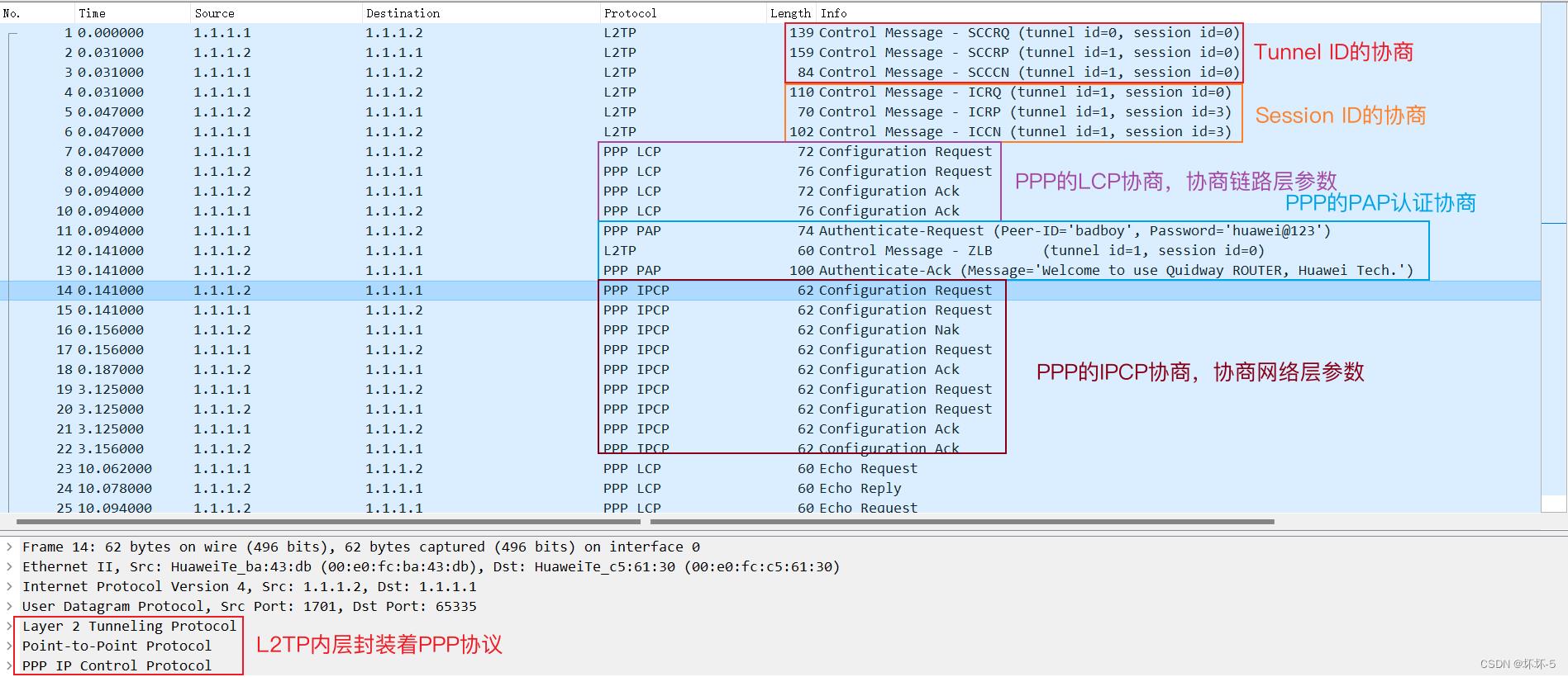
- 查找路由表后,发现是从VT接口发出,然后根据转发表,将数据包迭代到真实的物理接口,封装上新的IP报头后,源IP为1.1.1.1,目的IP为1.1.1.2,传输层使用的协议是UDP,源端口是随机产生的,目的端口是L2TP使用的1701,使用的封装协议是L2TP,内层协议是PPP,然后从物理接口发出
- 数据包到达LNS后,发现目的IP是自己,进行解封装,发现是L2TP的数据报文,拆掉外层包头后,查看内层的数据信息,再根据目的IP进行转发

- LNS配置
- 配置IP地址池,用于为LAC分配IP地址
| [LNS]ip pool l2tp [LNS-ip-pool-l2tp]section 1 192.168.1.2 192.168.1.5 |
- 配置L2TP的业务方案,即将L2TP与IP地址池进行绑定
| [LNS]aaa [LNS-aaa]service-scheme l2tp //配置L2TP的业务方案 [LNS-aaa-service-l2tp]ip-pool l2tp //在业务方案中,将用于给LAC分配地址的地址池进行绑定 |
- 配置认证域,并配置分支组以及分支组中的用户信息
| [LNS-aaa]domain default //默认的认证域 [LNS-aaa-domain-default]service-type l2tp //服务类型为L2TP [LNS]user-manage group /default/branch //创建分支组 [LNS]user-manage user badboy //创建用户 [LNS-localuser-badboy]alias huaihuai //配置别名 [LNS-localuser-badboy]parent-group /default/branch //将该用户添加到分支组下 [LNS-localuser-badboy]password huawei@123 //为该用户配置密码 |
- 创建的用户即用来做认证的用户
- 配置VT接口,并将接口划分进DMZ区域
| [LNS]interface Virtual-Template 1 [LNS-Virtual-Template1]ip ad 192.168.1.1 29 [LNS-Virtual-Template1]ppp authentication-mode pap //配置认证类型为PAP认证 [LNS-Virtual-Template1]remote service-scheme l2tp //与L2TP的业务方案进行绑定 [LNS]firewall zone dmz [LNS-zone-dmz]add int Virtual-Template 1 |
- 为VT接口配置的IP地址,不能是在LNS为LAC分配的IP地址池中的地址
- 在VT接口中,需要和AAA中的L2TP业务方案绑定,才能为对端分配IP地址
- 配置L2TP的组
| [LNS]l2tp enable [LNS]l2tp-group 1 [LNS-l2tp-2]allow l2tp virtual-template 1 remote LAC //指定接收呼叫时隧道对端的名称和VT接口 [LNS-l2tp-2]tunnel authentication //启用隧道认证 [LNS-l2tp-2]tunnel password cipher Huawei123 //配置隧道认证的密码 |
- 配置接收呼叫时的对端隧道名称一定要与LAC上配置的隧道名一致
- 配置缺省路由以及到达私网的静态路由
| ip route-static 0.0.0.0 0.0.0.0 1.1.1.1 ip route-static 10.2.2.1 255.255.255.255 172.16.2.1 |
- 配置区域间的安全策略
| security-policy rule name untrust_local source-zone untrust destination-zone local source-address 1.1.1.1 mask 255.255.255.255 destination-address 1.1.1.2 mask 255.255.255.255 service l2tp action permit | security-policy source-zone dmz destination-zone trust source-address 192.168.1.0 mask 255.255.255.248 destination-address 10.2.2.1 mask 255.255.255.255 action permit |
- 数据包从隧道收到后,数据包的源地址是1.1.1.1,目的地址是1.1.1.2,即防火墙自身的接口地址,所以匹配的源区域是Untrust,目的区域是自身的Local区域,需要放行L2TP服务
- 从隧道接口收到数据包,隧道口是属于DMZ区域的,所以匹配的源区域为DMZ,访问目的地址为Trust区域,因为在LAC上,已经做了SNAT的转换,所以匹配的源地址为LNS为LAC的VT接口分配的IP地址
配置SNAT
- 在LAC上配置源NAT,实现Client可以访问公网设备
- 配置NAT地址池
| nat address-group ISP 0 mode pat section 1 202.1.1.1 202.1.1.5 |
- 配置NAT策略
| nat-policy rule name ISP source-zone trust destination-zone untrust source-address 10.1.1.1 mask 255.255.255.255 action source-nat address-group ISP |
- 配置区域间的安全策略
| security-policy rule name ISP source-zone trust destination-zone untrust source-address 10.1.1.1 mask 255.255.255.255 action permit |
测试
- 在LAC上,在VT接口视图下,使用call-lns local-user badboy进行拨号连接LNS
- 在LAC的G1/0/1接口抓包,查看L2TP的连接信息

- 在LNS上查看L2TP隧道的建立情况

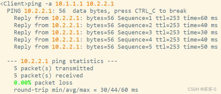
- 在Client上ping测试与Telnet Server的连通性,并在LAC上查看会话表项


- 可以正常访问,LAC上的会话表项可以看到,10.1.1.1的59307端口被转换为192.168.1.2的2049端口,对10.2.2.1的2048端口发起ICMP的访问
- l2tp的会话表项是建立的L2TP隧道,隧道的出口地址是1.1.1.2,目的端口是1701
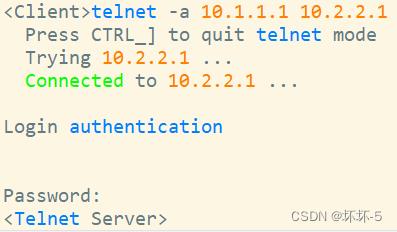
- 在Client上尝试登陆Tenlet Server,并查看LAC的会话表项


- 可以正常登录,并且防火墙上可以看到相应的会话表项
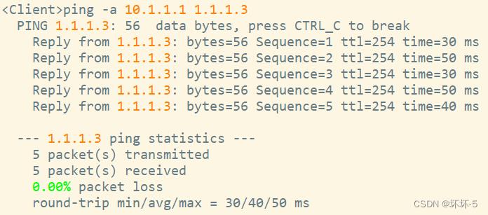
- 使用Client访问公网测试

- Client也可以正常访问公网
以上内容均属原创,如有不详或错误,敬请指出。
本文作者: 坏坏
版权声明: 本博客所有文章除特别声明外,均采用 CC BY-NC-SA 4.0 许可协议。转载请联系作者注明出处并附带本文链接!
以上是关于L2TP的LAC自动拨号实验的主要内容,如果未能解决你的问题,请参考以下文章