Polygon zkEVM可验证计算简单状态机示例
Posted mutourend
tags:
篇首语:本文由小常识网(cha138.com)小编为大家整理,主要介绍了Polygon zkEVM可验证计算简单状态机示例相关的知识,希望对你有一定的参考价值。
Next we show the arithmetization process of a more complex but yet simple state machine. Unlike the Fibonacci state machine, our simple state machine transitions from one state to the next in response to certain external instructions. See Figure 1 below, for such a state machine, with registries A \\textttA A and B \\textttB B, and a state ( A i , B i ) \\big(\\textttA^\\texttti,\\textttB^\\texttti\\big) (Ai,Bi) that changes to another state ( A i+2 , B i+2 ) \\big(\\textttA^\\texttti+2,\\textttB^\\texttti+2\\big) (Ai+2,Bi+2) in accordance to two instructions, Instruction i \\textttInstruction^\\texttti Instructioni and Instruction i+1 \\textttInstruction^\\texttti+1 Instructioni+1.
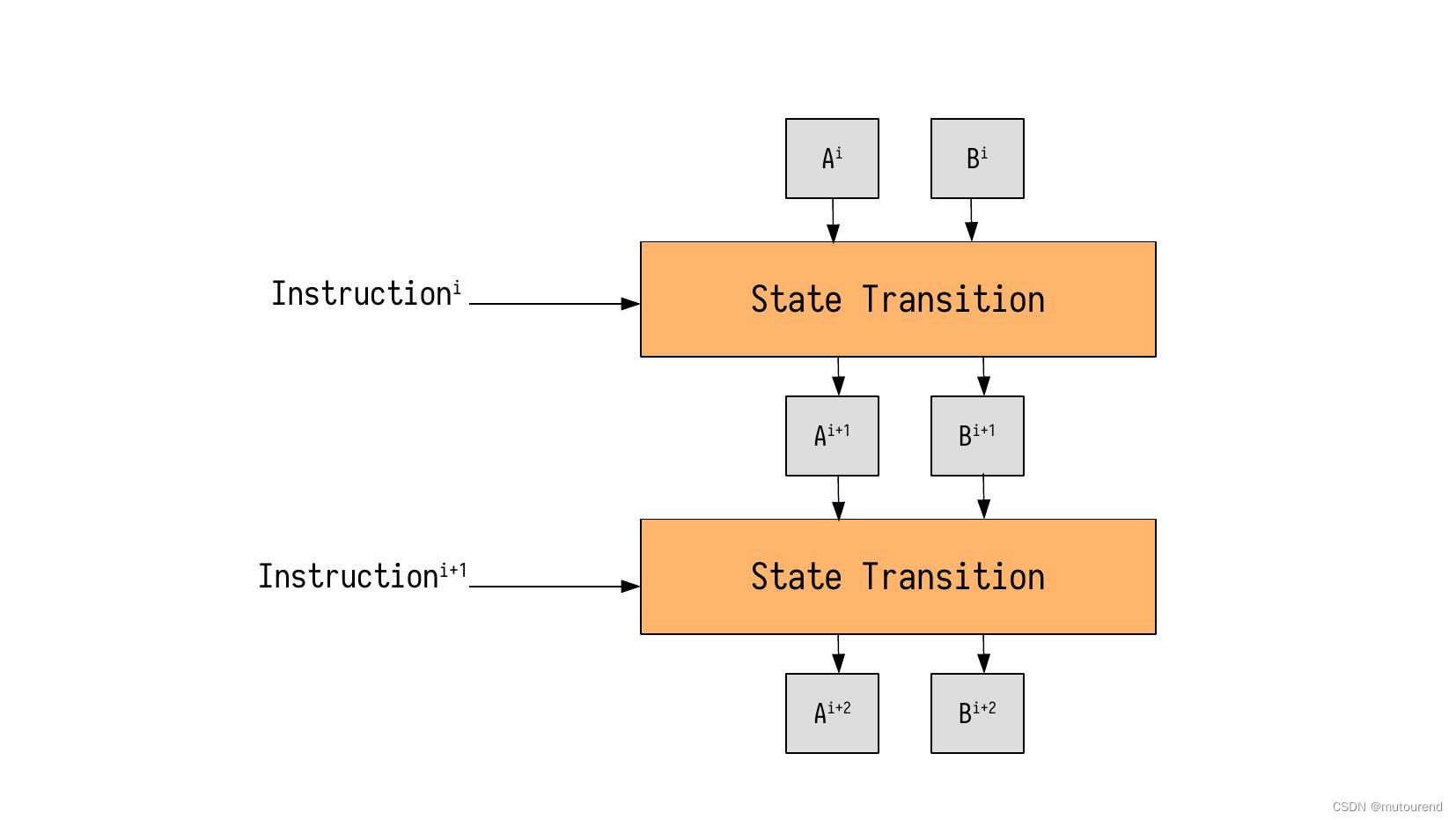
In the context of the zkProver, these instructions are written as zk-Assembly (zkASM) codes, and stored in a ROM in JSON-format.
State Machine Instructions
Suppose the above simple state machine receives an input, together with the following execution instruction, Instruction 1 \\textttInstruction^\\texttt1 Instruction1, written in Assembly.
Table 1: Instruction^1 written in zk-AssemblyInstruction 1 line 1 $ g e t I n p u t ( ) = > A line 2 3 = > B line 3 : A D D line 4 0 = > A , B \\beginarray|l|c| \\hline \\texttt & \\textttInstruction^\\texttt1 \\\\ \\hline \\textttline 1 & \\mathtt\\$\\getInput()\\ => A\\\\ \\hline \\textttline 2 & \\mathtt3 => B \\\\ \\hline \\textttline 3 & \\mathtt:ADD \\\\ \\hline \\textttline 4 & \\mathtt0 => A,B \\\\ \\hline \\endarray line 1line 2line 3line 4Instruction1$getInput()=>A3=>B:ADD0=>A,B
In accordance with each line of Instruction 1 \\textttInstruction^\\texttt1 Instruction1, the state machine executor must;
- line 1 \\textttline 1 line 1: Get a free input value and move it into register A \\textttA A.
- line 2 \\textttline 2 line 2: Move the value 3 \\mathtt3 3 into register B \\mathttB B.
- line 3 \\textttline 3 line 3: Compute the sum of registry values A \\mathttA A and B \\mathttB B, and save the output into register A \\mathttA A.
- line 4 \\textttline 4 line 4: Set the registers A \\mathttA A and B \\mathttB B to the value 0 \\mathtt0 0.
For a free input value of 7 7 7, the corresponding state transitions can be recorded in a table as follows;
Table 2: Record of all State ChangesInstruction 1 f r e e A A ′ B B ′ line 1 $ g e t I n p u t ( ) = > A 7 0 7 0 0 line 2 3 = > B 0 7 7 0 3 line 3 : A D D 0 7 10 3 3 line 4 0 = > A , B 0 10 0 3 0 \\beginarray|l|c|c|c|c|c|c| \\hline \\texttt & \\textttInstruction^\\texttt1 & \\mathttfree & \\mathttA & \\mathttA' & \\mathttB & \\mathttB' \\\\ \\hline \\textttline 1 & \\mathtt\\$\\getInput()\\ => A & 7 & 0 & 7 & 0 & 0 \\\\ \\hline \\textttline 2 & \\mathtt3 => B & 0 & 7 & 7 & 0 & 3 \\\\ \\hline \\textttline 3 & \\mathtt:ADD & 0 & 7 & 10 & 3 & 3 \\\\ \\hline \\textttline 4 & \\mathtt0 => A,B & 0 & 10 & 0 & 3 & 0 \\\\ \\hline \\endarray line 1line 2line 3line 4Instruction1$getInput()=>A3=>B:ADD0=>A,Bfree7000A07710A′77100B0033B′0330
Note that A ′ \\mathttA' A′ and B ′ \\mathttB' B′ denote the next state of the registers A \\mathttA A and B \\mathttB B, respectively.
Observe also that, each line of Instruction 1 \\textttInstruction^\\texttt1 Instruction1 does not always affect all register values. Since every register is initialised to 0 \\mathtt0 0 at the start, the state transitions are such that,
- line 1 \\textttline 1 line 1 only affects two registers; f r e e \\mathttfree free and A ′ \\mathttA' A′.
- line 2 \\textttline 2 line 2 affects the register B ′ \\mathttB' B′ alone. Any other state change is due to the rules and the logic of the state machine (i.e., changes in registers; f r e e \\mathttfree free and A \\mathttA A).
- line 3 \\textttline 3 line 3 affects the register A ′ \\mathttA' A′ alone. Again, the state change in register B \\mathttB B is due to the state machine’s rules and logic.
- line 4 \\textttline 4 line 4 affects only two registers; A ′ \\mathttA' A′ and B ′ \\mathttB' B′. The state change in register A \\mathttA A is also due to the rules and the logic of the state machine.
Computational Trace
Recall that the intention with developing these state machines is not only to carry out computations, but to also ensure that correctness of these computations is verifiable. In addition, verification must be achievable even by users with modest computer power. That said, keeping record of computations, as seen in Table 2 above, is not preferable for verification purposes, because the registry values can be very large for some state machines. And thus, defeating the ultimate purpose and aim of our rollup.
One therefore needs a way to keep track of all the computations and their correct execution, without requiring excessive memory. This is achieved by utilising the computational trace.
For our verification purposes, the computational trace does not capture the actual state values of each state transition, but uses selectors and setters to keep record of whether registry values have been altered (during each state transition) in a way that tallies with the received instructions.
Like switches that can either be ON or OFF, selectors and setters can also be either 1 \\mathtt1 1 or 0 \\mathtt0 0.
Rule for the inFree \\textttinFree inFree selector: Record inFree \\textttinFree inFree as 1 \\mathtt1 1 only if the value of the register free \\textttfree free is non-zero.
Rule for selectors setX \\\\textttsetX\\ setX: Each selector setX \\textttsetX setX is recorded;
- As the value 1 \\mathtt1 1, if the value of the corresponding registry X \\textttX X was involved in (or contributed to) the computation,
- Otherwise, selX \\textttselX selX is recorded as the value 0 \\mathtt0 0.
Rule for setters setY \\\\textttsetY\\ setY: Each setter setY \\textttsetY setY is recorded;
- As the value 1 \\mathtt1 1, if the corresponding registry value Y \\textttY Y was altered by the instruction,
- Or, as the value 0 \\mathtt0 0, otherwise.
The computational trace therefore consists mostly of bits, instead of large registry values.
In the zkEVM context, the computational trace is stored as a lookup table in the ROM of the relevant state machine.
Example (Computational Trace)
Take as an example, Instruction 1 \\textttInstruction^\\texttt1 Instruction