verilog怎么编写可调PWM波形?
Posted
tags:
篇首语:本文由小常识网(cha138.com)小编为大家整理,主要介绍了verilog怎么编写可调PWM波形?相关的知识,希望对你有一定的参考价值。
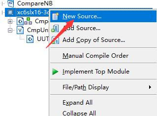
参考技术A首先,在项目上右键,点击New Source创建新的代码文件。
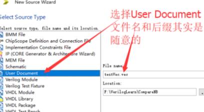
选择User Document创建自定义的文本文件。文件名和后缀都随意了。该文件用来存放仿真需要的数据,与项目本身并无关联。
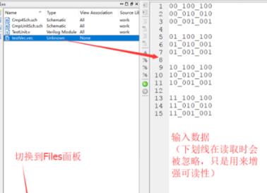
创建好后,在下方切换到Files面板,双击打开该文件
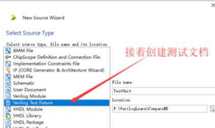
数据文件写好后,就要编写Verilog测试模块读取该文件并对模块进行测试了。在项目上右键,点击New Source,接着选择Verilog Test Fixture,输入文件名并继续,选择待测模块,接着创建文件。
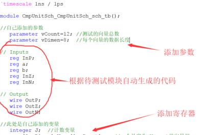
双击打开该文件,看到待测试模块输入对应了一些reg寄存器类型,输出部分对应了一些wire类型。添加两个parameter常量,接着添加计数变量J用于for循环,添加一个向量数组用于存放文件读取的数据。
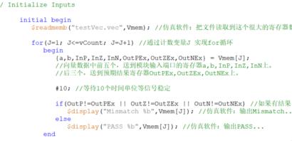
其中$readmemb函数从文件读取数据到Vmem数组。$display可以在仿真软件中输出文字。#10表示等待10个时间单位,等"信号稳定"
Verilog HDL是一种硬件描述语言(HDL:Hardware Description Language),以文本形式来描述数字系统硬件的结构和行为的语言,用它可以表示逻辑电路图、逻辑表达式,还可以表示数字逻辑系统所完成的逻辑功能。 Verilog HDL和VHDL是世界上最流行的两种硬件描述语言,都是在20世纪80年代中期开发出来的。
语言要素:Verilog的设计初衷是成为一种基本语法与C语言相近的硬件描述语言。这是因为C语言在Verilog设计之初,已经在许多领域得到广泛应用,C语言的许多语言要素已经被许多人习惯。一种与C语言相似的硬件描述语言,可以让电路设计人员更容易学习和接受。不过,Verilog与C语言还是存在许多差别。
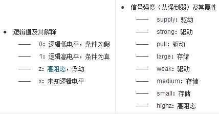
数据类型:四值逻辑
请问verilog编写的PWM的死区怎么编写?
参考技术A 很坚定,编写俩个输出PWM1,PWM2,他们之间是几何对称关系。。。。。。这样他们就有一定的死区了,功率放大器CMOS不完全导通 参考技术B 首先要清楚死区是怎么回事,避免驱动器上、下桥臂直通才是问题的本质。 参考技术C 用Verilog实现的PWM硬件。//-----------------------------32 bits pwm controller------------------------//
//the width is negative
module pwm(clk,write_data,cs,write_n,addr,clr_n,read_data,pwm_out);
//----------------------define the inout put-------------------------//
input clk,cs,clr_n;
input addr;
input write_n;
output pwm_out;
output [31:0] read_data;
input [31:0] write_data;
//--------------------define regs and wires--------------------------//
reg [31:0] period;
reg [31:0] pulse_width;
reg [31:0] counter;
reg off;
reg [31:0] read_data;
wire period_en, pulse_width_en; //enable to write
//-------------------------------------------------------------------//
//define the content of period and pulse_width
always @(posedge clk or negedge clr_n)
begin
if (clr_n==0)
begin
period<=32'h 00000000;
pulse_width<=32'h 00000000;
end
else
begin
if (period_en)//write in preiod data
period<=write_data[31:0];
else
period<=period;
if (pulse_width_en)//write in width data
pulse_width<=write_data[31:0];
else
pulse_width<=pulse_width;
end
end
//------------------------------------------------------------------//
//visit the regs
always @(addr or period or pulse_width)
begin
if (addr == 0)
read_data=period;
else
read_data=pulse_width;
end
//-------------------------------------------------------------------//
//the logic to generate pwm
//the period of pwm
always @(posedge clk or negedge clr_n)
begin
if (clr_n==0)
counter<=0;
else
begin
if (counter>=period-1)
counter<=0;
else
counter<=counter+1;
end
end
//-----------------------------------------------------//
//ajust the width of pwm
always @(posedge clk or negedge clr_n)
begin
if (clr_n==0)
off<=0;
else
if (counter>=pulse_width)
off <= 1;
else
if (counter==0)
off<=0;
else
off<=off;
end
assign period_en = cs & !write_n & !addr;
assign pulse_width_en = cs & !write_n & addr;
//PWM output
assign pwm_out=!off;
endmodule
以上是关于verilog怎么编写可调PWM波形?的主要内容,如果未能解决你的问题,请参考以下文章