嵌入式图像上实现软件画线
Posted coding码场
tags:
篇首语:本文由小常识网(cha138.com)小编为大家整理,主要介绍了嵌入式图像上实现软件画线相关的知识,希望对你有一定的参考价值。
在一些嵌入式产品上,经常会遇到要在图像上画线,比如图像上识别出某个物体需要把它框起来,车辆识别需要把识别出来的车框起来,画出框了,看起来就有点味道了,至少说明你真的识别出来了,产品体验上是一个刚需。
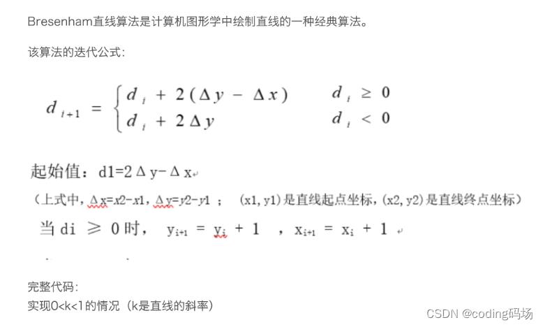
当然单从画线来说,有GUI的产品就太简单了,GUI都有直接的画线接口,这样确实挺简单的。那么在一些没有GUI支持的系统怎么办呢?又不想去借把牛刀来!那么久需要从在图像上直接画出来,也就是改变一下图像上的像素点的值,组成我们需要的线条的表现形式。比较成熟的画线软件算法有布雷森汉姆算法画线,相当经典。如下:

软件代码实现图像先以YUV420SP来说吧!
我们知道YUV420SP的图像有两个plane,Y在一个plane上,uv在另外一个plane上,比起uv的plane大小只有Y的一半大小,那么我们在要替换相应像素点的yuv值得时候就可以找到对应的Y和UV的值。DrawPoint的实现如下:
     Color = 0;
     case V4L2_PIX_FMT_NV12:

           int Yoffset = PntY * ImgW + PntX;
           int Uoffset,Voffset;

           Uoffset =  ImgH * ImgW + (PntY / 2) * ImgW + PntX / 2 * 2 ;
           Voffset =  Uoffset + 1;

           YuvBuf[Yoffset] = s_color_table[Color].Y;
           YuvBuf[Uoffset] = s_color_table[Color].U;
           YuvBuf[Voffset] = s_color_table[Color].V;
从替换点的yuv值我们可以看出,ImgH,ImgW是图像的宽高, PntY,PntX就是具体像素点位置,要有一个颜色的对应值,支持的颜色多了,我们弄一个颜色对照表,把主要颜色支持上就行了。如下:
static stYuvColor s_color_table[12] =

 0x00, 0x00, 0x00, // green
 0x00, 0x00, 0xff, // red
 0x00, 0xff, 0x00, // blue
 0x00, 0xff, 0xff, // purple
 0xff, 0x00, 0x00, // dark green
 0xff, 0x00, 0xff, // yellow
 0xff, 0xff, 0x00, // light blue
 0xff, 0xff, 0xff, // light purple
 0x00, 0x80, 0x80, // dark black
 0x80, 0x80, 0x80, // gray
 0xff, 0x80, 0x80, // white

;
下面就来看看画一条线怎么弄
int YUY_Draw_Line(unsigned char * YuvBuf, int ImgW, int ImgH, int fmt,int SPntX, int SPntY,int EPntX, int EPntY, int Color)

   int ret = -1;
   if(YuvBuf == NULL)
       return ret;

 //  printf("SPntX=%d,EPntX=%d,SPntY=%d,EPntY=%d\\n", SPntX, EPntX, SPntY, EPntY);

   SPntX = (SPntX + 1>= ImgW) ? (ImgW - 1) : (SPntX < 0 ? 0 : SPntX);
   EPntX = (EPntX + 1>= ImgW) ? (ImgW - 1) : (EPntX < 0 ? 0 : EPntX);
   SPntY = (SPntY + 1>= ImgH) ? (ImgH - 1) : (SPntY < 0 ? 0 : SPntY);
   EPntY = (EPntY + 1>= ImgH) ? (ImgH - 1) : (EPntY < 0 ? 0 : EPntY);

   int dx = (SPntX > EPntX) ? (SPntX - EPntX) : (EPntX - SPntX);
   int dy = (SPntY > EPntY) ? (SPntY - EPntY) : (EPntY - SPntY);
   int xstep = (SPntX < EPntX) ? 1 : -1;
   int ystep = (SPntY < EPntY) ? 1 : -1;
   int nstep = 0, eps = 0;
   int pointX = SPntX;
   int pointY = SPntY;
  // printf("dx=%d,dy=%d,xstep=%d,ystep=%d,pointX=%d,pointY=%d\\n",
  //         dx, dy, xstep, ystep, pointX, pointY);

    if(dx > dy)

       while(nstep <= dx)

           ret = YUY_Draw_Piont(YuvBuf, ImgW, ImgH, fmt, pointX, pointY, Color);
           if(ret < 0)
               break;

           eps += dy;
           if( (eps << 1) >= dx )

               pointY += ystep;
               eps -= dx;

           pointX += xstep;
           nstep++;


   else

       while(nstep <= dy)

           ret = YUY_Draw_Piont(YuvBuf, ImgW, ImgH, fmt, pointX, pointY, Color);
           if(ret < 0)
               break;

           eps += dx;
           if( (eps << 1) >= dy )

               pointX += xstep;
               eps -= dy;

               pointY += ystep;
               nstep++;


   return ret;
有了线,我们来画个框吧!也就是4条线围起来,加一点强度,来一个控制线宽的参数:
int YUV_Draw_Rect(unsigned char *YuvBuf, int ImgW, int ImgH, int fmt,RECT* Rect, int Color,int lineWidth)

   int ret = -1;
   int line_width = 1;

   if(YuvBuf == NULL)
       return ret;

   if(Rect->bottom == Rect->top || Rect->left == Rect->right)
       return ret;

   if(lineWidth > 10)
      line_width = 10;//max try 10 pixel
   else if(0 == lineWidth)
       line_width = 1;//correct to 1
   else
       line_width = lineWidth;//max try 10 pixel

    for(int i=0; i < line_width ; i++)
       // top --
       YUY_Draw_Line(YuvBuf, ImgW, ImgH,fmt, Rect->left, Rect->top+i , Rect->right, Rect->top+i, Color);
       // left |
       YUY_Draw_Line(YuvBuf, ImgW, ImgH,fmt, Rect->right-i, Rect->top, Rect->right-i, Rect->bottom, Color);
       // right |
       YUY_Draw_Line(YuvBuf, ImgW, ImgH,fmt, Rect->left+i, Rect->top , Rect->left+i,  Rect->bottom, Color);
       // bottom --
       YUY_Draw_Line(YuvBuf, ImgW, ImgH,fmt, Rect->left,  Rect->bottom-i, Rect->right, Rect->bottom-i, Color);


   return 0;
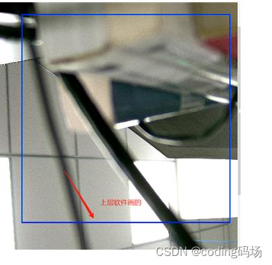
里面加了一个线宽最大控制到10个像素,当然也可以根据需要自己调整。看看效果吧!


看起来整个效果还是不错的,当然只是展示了一种YUV420SP的图像上画线,其他格式的只要把握好像素点的构成,以及像素点值得分布,来想办法替换掉就行了。思路是一样的。
以上是关于嵌入式图像上实现软件画线的主要内容,如果未能解决你的问题,请参考以下文章